Tài liệu Designing with FPGAs and CPLDs- P4 pptx
Bạn đang xem bản rút gọn của tài liệu. Xem và tải ngay bản đầy đủ của tài liệu tại đây (137.77 KB, 30 trang )
74 Chapter 5: Design Techniques, Rules, and Guidelines
Objectives
This chapter focuses on the potential problems that an engineer must recognize
when designing an FPGA or CPLD and the design techniques that are used to
avoid these problems. More specifically, reading this chapter will help you:
• Learn the fundamental concepts of hardware description languages.
• Appreciate the process of top-down design and how it is used to organize a
design and speed up the development time.
• Comprehend how FPGA and CPLD architecture and internal structures
affect your design.
• Understand the concept of synchronous design, know how to spot asynchro-
nous circuits, and how to redesign an asynchronous circuit to be synchro-
nous.
• Recognize what problems floating internal nodes can cause and learn how to
avoid these problems.
• Understand the consequences of bus contention and techniques for avoiding it.
• Comprehend one-hot state encoding for optimally creating state machines in
FPGAs.
• Design testability into a circuit from the beginning and understand various
testability structures that are available.
5.1 Hardware Description Languages
Design teams can use a hardware description language to design at any level of
abstraction, from high level architectural models to low-level switch models.
These levels, from least amount of detail to most amount of detail are as fol-
lows:
• Behavioral models
• Algorithmic
• Architectural
• Structural models
• Register Transfer Level (RTL)
• Gate level
• Switch level
These levels refer to the types of models that are used to represent a circuit
design. The top two levels use what are called behavioral models, whereas the
lower three levels use what are called structural models. Behavioral models con-
Please purchase PDF Split-Merge on www.verypdf.com to remove this watermark.
Hardware Description Languages 75
sist of code that represents the behavior of the hardware without respect to its
actual implementation. Behavioral models don't include timing numbers. Buses
don't need to be broken down into their individual signals. Adders can simply
add two or more numbers without specifying registers or gates or transistors.
The two types of behavioral models are called algorithmic models and architec-
tural models.
Algorithmic models simply represent algorithms that act on data. No hard-
ware implementation is implied in an algorithmic model. So an algorithmic
model is similar to what a programmer might write in C or Java to describe a
function. The algorithmic model is coded to be fast, efficient, and mathemati-
cally correct. An algorithmic model of a circuit can be simulated to test that the
basic specification of the design is correct.
Architectural models specify the blocks that implement the algorithms.
Architectural models may be divided into blocks representing PC boards, ASICs,
FPGAs, or other major hardware components of the system, but they do not
specify how the algorithms are implemented in each particular block. These
models of a circuit can be compared to an algorithmic model of the same circuit
to discover if a chip’s architecture is correctly implementing the algorithm. The
design team can simulate the algorithmic model to find bottlenecks and ineffi-
ciencies before any of the low level design has begun.
Some sample behavioral level HDL code is shown in Listing 5.1. This sample
shows a multiplier for two unsigned numbers of any bit width. Notice the very
high level of description — there are no references to gates or clock signals.
Structural models consist of code that represents specific pieces of hardware.
RTL specifies the logic on a register level. In other words, the simplest RTL code
specifies register logic. Actual gates are avoided, although RTL code may use
Boolean functions that can be implemented in gates. The example RTL code in
Listing 5.2 shows a multiplier for two unsigned 4-bit numbers. This level is the
level at which most digital design is done.
Listing 5.1 Sample behavioral level HDL code
// *****************************************************
// ***** Multiplier for two unsigned numbers *****
// *****************************************************
// Look for the multiply enable signal
always @(posedge multiply_en) begin
product <= a*b;
end
Please purchase PDF Split-Merge on www.verypdf.com to remove this watermark.
76 Chapter 5: Design Techniques, Rules, and Guidelines
Gate level modeling consists of code that specifies gates such as NAND and
NOR gates (Listing 5.3) Gate level code is often the output of a synthesis pro-
gram that reads the RTL level code that an engineer has used to design a chip
and writes the gate level equivalent. This gate level code can then be optimized
for placement and routing within the CPLD or FPGA. The code in Listing 5.3
shows the synthesized 4-bit unsigned multiplier where the logic has been
mapped to individual CLBs of an FPGA. Notice that at this level all logic must
be described in primitive functions that map directly to the CLB logic, making
the code much longer.
Listing 5.2 Sample RTL HDL code
// *****************************************************
// ***** Multiplier for two unsigned 4-bit numbers *****
// *****************************************************
// Look at the rising edge of the clock
always @(posedge clk) begin
if (multiply_en == 1) begin // Set up the multiplication
count <= ~0; // Set count to its max value
product <= 0; // Zero the product
end
if (count) begin
if (b[count]) begin
// If this bit of the multiplier is 1, shift
// the product left and add the multiplicand
product <= (product << 1) + a;
end
else begin
// If this bit of the multiplier is 0,
// just shift the product left
product <= product << 1;
end
count <= count - 1; // Decrement the count
end
end
Please purchase PDF Split-Merge on www.verypdf.com to remove this watermark.
Hardware Description Languages 77
(In fact, much of the code was removed for clarity. Buffers used to route sig-
nals and the Boolean logic for the lookup tables (LUTs) are not included in this
code, even though they would be needed in a production chip.)
Listing 5.3 Sample gate level HDL code
// *****************************************************
// ***** Multiplier for two unsigned 4-bit numbers *****
// *****************************************************
module UnsignedMultiply (
clk,
a,
b,
multiply_en,
product);
input clk;
input [3:0] a;
input [3:0] b;
input multiply_en;
output [7:0] product;
wire clk ;
wire [3:0] a;
wire [3:0] b;
wire multiply_en ;
wire [7:0] product;
wire [3:0] count;
wire [7:0] product_c;
wire [3:0] a_c;
wire [7:0] product_10;
wire [3:0] b_c;
wire clk_c ;
wire count16 ;
wire un1_count_5_axb_1 ;
wire un1_count_5_axb_2 ;
wire un7_product_axb_1 ;
Please purchase PDF Split-Merge on www.verypdf.com to remove this watermark.
78 Chapter 5: Design Techniques, Rules, and Guidelines
wire un7_product_axb_2 ;
wire un7_product_axb_3 ;
wire un7_product_axb_4 ;
wire un7_product_axb_5 ;
wire un1_un1_count16_i ;
wire multiply_en_c ;
wire un1_multiply_en_1_0 ;
wire product25_3_0_am ;
wire product25_3_0_bm ;
wire product25 ;
wire un7_product_axb_0 ;
wire un7_product_s_1 ;
wire un7_product_s_2 ;
wire un7_product_s_3 ;
wire un7_product_s_4 ;
wire un7_product_s_5 ;
wire un7_product_s_6 ;
wire un1_count_5_axb_0 ;
wire un1_count_5_axb_3 ;
wire un7_product_axb_6 ;
wire un1_count_5_s_1 ;
wire un1_count_5_s_2 ;
wire un1_count_5_s_3 ;
wire un7_product_cry_5 ;
wire un7_product_cry_4 ;
wire un7_product_cry_3 ;
wire un7_product_cry_2 ;
wire un7_product_cry_1 ;
wire un7_product_cry_0 ;
wire un1_count_5_cry_2 ;
wire un1_count_5_cry_1 ;
wire un1_count_5_cry_0 ;
LUT2_6 un1_count_5_axb_1_Z (
.I0(count[1]),
Listing 5.3 Sample gate level HDL code (Continued)
Please purchase PDF Split-Merge on www.verypdf.com to remove this watermark.
Hardware Description Languages 79
.I1(count16),
.O(un1_count_5_axb_1));
LUT2_6 un1_count_5_axb_2_Z (
.I0(count[2]),
.I1(count16),
.O(un1_count_5_axb_2));
LUT2_6 un7_product_axb_1_Z (
.I0(product_c[1]),
.I1(a_c[2]),
.O(un7_product_axb_1));
LUT2_6 un7_product_axb_2_Z (
.I0(product_c[2]),
.I1(a_c[3]),
.O(un7_product_axb_2));
LUT1_2 un7_product_axb_3_Z (
.I0(product_c[3]),
.O(un7_product_axb_3));
LUT1_2 un7_product_axb_4_Z (
.I0(product_c[4]),
.O(un7_product_axb_4));
LUT1_2 un7_product_axb_5_Z (
.I0(product_c[5]),
.O(un7_product_axb_5));
FDE \product_Z[7] (
.Q(product_c[7]),
.D(product_10[7]),
.C(clk_c),
.CE(un1_un1_count16_i));
Listing 5.3 Sample gate level HDL code (Continued)
Please purchase PDF Split-Merge on www.verypdf.com to remove this watermark.
80 Chapter 5: Design Techniques, Rules, and Guidelines
FDE \product_Z[0] (
.Q(product_c[0]),
.D(product_10[0]),
.C(clk_c),
.CE(un1_un1_count16_i));
FDE \product_Z[1] (
.Q(product_c[1]),
.D(product_10[1]),
.C(clk_c),
.CE(un1_un1_count16_i));
FDE \product_Z[2] (
.Q(product_c[2]),
.D(product_10[2]),
.C(clk_c),
.CE(un1_un1_count16_i));
FDE \product_Z[3] (
.Q(product_c[3]),
.D(product_10[3]),
.C(clk_c),
.CE(un1_un1_count16_i));
FDE \product_Z[4] (
.Q(product_c[4]),
.D(product_10[4]),
.C(clk_c),
.CE(un1_un1_count16_i));
FDE \product_Z[5] (
.Q(product_c[5]),
.D(product_10[5]),
.C(clk_c),
Listing 5.3 Sample gate level HDL code (Continued)
Please purchase PDF Split-Merge on www.verypdf.com to remove this watermark.
Hardware Description Languages 81
.CE(un1_un1_count16_i));
FDE \product_Z[6] (
.Q(product_c[6]),
.D(product_10[6]),
.C(clk_c),
.CE(un1_un1_count16_i));
LUT2_4 un1_multiply_en_1 (
.I0(count16),
.I1(multiply_en_c),
.O(un1_multiply_en_1_0));
MUXF5 product25_3_0 (
.I0(product25_3_0_am),
.I1(product25_3_0_bm),
.S(count[1]),
.O(product25));
LUT3_D8 product25_3_0_bm_Z (
.I0(count[0]),
.I1(b_c[3]),
.I2(b_c[2]),
.O(product25_3_0_bm));
LUT3_D8 product25_3_0_am_Z (
.I0(count[0]),
.I1(b_c[1]),
.I2(b_c[0]),
.O(product25_3_0_am));
LUT4_A280 \product_10_Z[1] (
.I0(count16),
.I1(product25),
.I2(un7_product_axb_0),
Listing 5.3 Sample gate level HDL code (Continued)
Please purchase PDF Split-Merge on www.verypdf.com to remove this watermark.
82 Chapter 5: Design Techniques, Rules, and Guidelines
.I3(product_c[0]),
.O(product_10[1]));
LUT4_A280 \product_10_Z[2] (
.I0(count16),
.I1(product25),
.I2(un7_product_s_1),
.I3(product_c[1]),
.O(product_10[2]));
LUT4_A280 \product_10_Z[3] (
.I0(count16),
.I1(product25),
.I2(un7_product_s_2),
.I3(product_c[2]),
.O(product_10[3]));
LUT4_A280 \product_10_Z[4] (
.I0(count16),
.I1(product25),
.I2(un7_product_s_3),
.I3(product_c[3]),
.O(product_10[4]));
LUT4_A280 \product_10_Z[5] (
.I0(count16),
.I1(product25),
.I2(un7_product_s_4),
.I3(product_c[4]),
.O(product_10[5]));
LUT4_A280 \product_10_Z[6] (
.I0(count16),
.I1(product25),
.I2(un7_product_s_5),
Listing 5.3 Sample gate level HDL code (Continued)
Please purchase PDF Split-Merge on www.verypdf.com to remove this watermark.
Hardware Description Languages 83
.I3(product_c[5]),
.O(product_10[6]));
LUT4_A280 \product_10_Z[7] (
.I0(count16),
.I1(product25),
.I2(un7_product_s_6),
.I3(product_c[6]),
.O(product_10[7]));
LUT2_6 un1_count_5_axb_0_Z (
.I0(count[0]),
.I1(count16),
.O(un1_count_5_axb_0));
LUT2_6 un1_count_5_axb_3_Z (
.I0(count[3]),
.I1(count16),
.O(un1_count_5_axb_3));
LUT2_6 un7_product_axb_0_Z (
.I0(product_c[0]),
.I1(a_c[1]),
.O(un7_product_axb_0));
LUT1_2 un7_product_axb_6_Z (
.I0(product_c[6]),
.O(un7_product_axb_6));
LUT4_FFFE count16_Z (
.I0(count[2]),
.I1(count[3]),
.I2(count[0]),
.I3(count[1]),
.O(count16));
Listing 5.3 Sample gate level HDL code (Continued)
Please purchase PDF Split-Merge on www.verypdf.com to remove this watermark.
84 Chapter 5: Design Techniques, Rules, and Guidelines
LUT3_80 \product_10_Z[0] (
.I0(count16),
.I1(product25),
.I2(a_c[0]),
.O(product_10[0]));
LUT2_E un1_un1_count16_i_Z (
.I0(multiply_en_c),
.I1(count16),
.O(un1_un1_count16_i));
FDS \count_Z[0] (
.Q(count[0]),
.D(un1_count_5_axb_0),
.C(clk_c),
.S(un1_multiply_en_1_0));
FDS \count_Z[1] (
.Q(count[1]),
.D(un1_count_5_s_1),
.C(clk_c),
.S(un1_multiply_en_1_0));
FDS \count_Z[2] (
.Q(count[2]),
.D(un1_count_5_s_2),
.C(clk_c),
.S(un1_multiply_en_1_0));
FDS \count_Z[3] (
.Q(count[3]),
.D(un1_count_5_s_3),
.C(clk_c),
.S(un1_multiply_en_1_0));
Listing 5.3 Sample gate level HDL code (Continued)
Please purchase PDF Split-Merge on www.verypdf.com to remove this watermark.
Hardware Description Languages 85
XORCY un7_product_s_6_Z (
.LI(un7_product_axb_6),
.CI(un7_product_cry_5),
.O(un7_product_s_6));
XORCY un7_product_s_5_Z (
.LI(un7_product_axb_5),
.CI(un7_product_cry_4),
.O(un7_product_s_5));
MUXCY_L un7_product_cry_5_Z (
.DI(GND),
.CI(un7_product_cry_4),
.S(un7_product_axb_5),
.LO(un7_product_cry_5));
XORCY un7_product_s_4_Z (
.LI(un7_product_axb_4),
.CI(un7_product_cry_3),
.O(un7_product_s_4));
MUXCY_L un7_product_cry_4_Z (
.DI(GND),
.CI(un7_product_cry_3),
.S(un7_product_axb_4),
.LO(un7_product_cry_4));
XORCY un7_product_s_3_Z (
.LI(un7_product_axb_3),
.CI(un7_product_cry_2),
.O(un7_product_s_3));
MUXCY_L un7_product_cry_3_Z (
.DI(GND),
Listing 5.3 Sample gate level HDL code (Continued)
Please purchase PDF Split-Merge on www.verypdf.com to remove this watermark.
86 Chapter 5: Design Techniques, Rules, and Guidelines
.CI(un7_product_cry_2),
.S(un7_product_axb_3),
.LO(un7_product_cry_3));
XORCY un7_product_s_2_Z (
.LI(un7_product_axb_2),
.CI(un7_product_cry_1),
.O(un7_product_s_2));
MUXCY_L un7_product_cry_2_Z (
.DI(product_c[2]),
.CI(un7_product_cry_1),
.S(un7_product_axb_2),
.LO(un7_product_cry_2));
XORCY un7_product_s_1_Z (
.LI(un7_product_axb_1),
.CI(un7_product_cry_0),
.O(un7_product_s_1));
MUXCY_L un7_product_cry_1_Z (
.DI(product_c[1]),
.CI(un7_product_cry_0),
.S(un7_product_axb_1),
.LO(un7_product_cry_1));
MUXCY_L un7_product_cry_0_Z (
.DI(product_c[0]),
.CI(GND),
.S(un7_product_axb_0),
.LO(un7_product_cry_0));
XORCY un1_count_5_s_3_Z (
.LI(un1_count_5_axb_3),
.CI(un1_count_5_cry_2),
Listing 5.3 Sample gate level HDL code (Continued)
Please purchase PDF Split-Merge on www.verypdf.com to remove this watermark.
Hardware Description Languages 87
Finally, the lowest level is that of a switch level model. A switch level model
specifies the actual transistor switches that are combined to make gates. Digital
design is never done at this level. Switch level code can be used for physical
design of an ASIC and can also be used for the design of analog devices.
The advantage of HDLs is that they enable all of these different levels of
modeling within the same language. This makes all the stages of design very
.O(un1_count_5_s_3));
XORCY un1_count_5_s_2_Z (
.LI(un1_count_5_axb_2),
.CI(un1_count_5_cry_1),
.O(un1_count_5_s_2));
MUXCY_L un1_count_5_cry_2_Z (
.DI(count[2]),
.CI(un1_count_5_cry_1),
.S(un1_count_5_axb_2),
.LO(un1_count_5_cry_2));
XORCY un1_count_5_s_1_Z (
.LI(un1_count_5_axb_1),
.CI(un1_count_5_cry_0),
.O(un1_count_5_s_1));
MUXCY_L un1_count_5_cry_1_Z (
.DI(count[1]),
.CI(un1_count_5_cry_0),
.S(un1_count_5_axb_1),
.LO(un1_count_5_cry_1));
MUXCY_L un1_count_5_cry_0_Z (
.DI(count[0]),
.CI(GND),
.S(un1_count_5_axb_0),
.LO(un1_count_5_cry_0));
endmodule /* UnsignedMultiply */
Listing 5.3 Sample gate level HDL code (Continued)
Please purchase PDF Split-Merge on www.verypdf.com to remove this watermark.
88 Chapter 5: Design Techniques, Rules, and Guidelines
convenient to implement. You don't need to learn different tools. You can easily
simulate the design at a behavioral level, and then substitute various behavioral
code modules with structural code modules. For system simulation, this allows
you to analyze your entire project using the same set of tools. First, you can test
and optimize the algorithms. Next, you can use the behavioral models to parti-
tion the hardware into boards, ASIC, and FPGAs. You can then write the RTL
code and substitute it for behavioral blocks, one at a time, to easily test the func-
tionality of each block. From that, you can synthesize the design, creating gate
and switch level blocks that can be resimulated with timing numbers to get
actual performance measurements. Finally, you can use this low-level code to
generate a netlist for layout. All stages of the design have been performed using
the same basic tool.
The main HDLs in existence today are Verilog and VHDL. Both are open
standards, maintained by standards groups of the Institute of Electrical and
Electronic Engineers (IEEE). VHDL is maintained as IEEE-STD-1076; Verilog is
maintained as IEEE-STD-1364. Although some engineers prefer one language
over the other, the differences are minor. As these standard languages progress
with new versions, the differences become even fewer. Also, several languages,
including C++, are being offered as a system level language, which would enable
engineers to design and simulate an entire system consisting of multiple chips,
boards, and software. These system level design languages are still evolving.
5.2 Top-Down Design
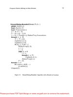
Top-down design is the design methodology whereby high level functions are
defined first, and the lower level implementation details are filled in later. A
design can be viewed as a hierarchical tree, as shown in Figure 5.1. The top level
block represents the entire chip. The next lower level blocks also represent the
entire chip but divided into the major function blocks of the chip. Intermediate
level blocks divide the functionality into more manageable pieces. The bottom
level contains only gates and macrofunctions, which are vendor-supplied high
level functions.
5.2.1 Use of Hardware Design Languages
Top-down design methodology lends itself particularly well to using HDLs, the
generally accepted method of designing complex CPLDs and FPGAs. Each block
in the design corresponds to the code for a self-contained module. The top-level
blocks correspond to the behavioral models that comprise the chip. The inter-
mediate levels correspond to the RTL models that will become input to the syn-
thesis process. The lowest level of the hierarchy corresponds to gate level code
Please purchase PDF Split-Merge on www.verypdf.com to remove this watermark.
Top-Down Design 89
which is output from the synthesis software and which directly represents logic
structures within the chip.
5.2.2 Written Specifications
Top-down design methodology works hand in hand with a written specification
that, as discussed in Chapter 4, is an essential starting point for any design. The
specification must include general aspects of the design, including the major
functional blocks. The highest blocks of a top-down design are behavioral level
models that correspond to the major functional blocks described in the specifica-
tion. Thus, using a top-down design approach, the specification becomes a start-
ing point for the actual HDL code. Specification changes can immediately be
turned into HDL design changes, and design changes can be quickly and easily
translated back to the specification, keeping the specification accurate and up to
date.
5.2.3 Allocating Resources
These days, chips typically incorporate a large number of gates and a very high
level of functionality. A top-down approach simplifies the design task and
allows more than one engineer, when necessary, to design the chip. For example,
the lead designer or the system architect may be responsible for the specification
and the top-level block. Engineers in the design team may each be responsible
for one or several intermediate blocks, depending on their strengths, experience,
and abilities. An experienced ALU designer may be responsible for the ALU
block and several other blocks. A junior engineer can work on a smaller block,
such as a bus controller. Each engineer can work in parallel, writing code and
simulating, until it is time to integrate the pieces into a single design. No one
11
12
13
14
15
16
17
18
19
20
21
22
23
24
5
6
1
2
3
4
8
10
9
7
Behavioral
RTL
Gate
Figure 5.1 Top-down design
Please purchase PDF Split-Merge on www.verypdf.com to remove this watermark.
90 Chapter 5: Design Techniques, Rules, and Guidelines
person can slow down the entire design. With a top-down design, your
not-too-bright colleague in the next cubicle won’t delay the entire project or
make you look bad. That may be the single best reason for using this design
methodology.
5.2.4 Design Partitioning
Even if you are the only engineer designing the chip, this methodology allows
you to break the design into simpler functions that you (or others) can design
and simulate independently from the rest of the design. A large, complex design
becomes a series of independent smaller ones that are easier to design and simu-
late.
5.2.5 Flexibility and Optimization
Top-down design allows flexibility. Teams can remove sections of the design and
replace them with higher-performance or optimized designs without affecting
other sections of the design. Adding new or improved functionality involves sim-
ply redesigning one section of the design and substituting it for the current sec-
tion.
5.2.6 Reusability
Reusability is an important topic in chip design these days. In the days when a
CPLD consisted of a few small state machines, it was no big deal to design it
from scratch. Nowadays, CPLDs and FPGAs contain so much logic that reusing
any function from a previous design can save days, weeks, or months of design
time. When one group has already designed a certain function, say a fast, effi-
cient 64-bit multiplier, HDLs allow you to take the design and reuse it in your
design. If you need a 64-bit multiplier, you can simply take the designed, verified
code and plop it into your design. Or you can purchase the code from a third
party. But it will only fit easily into your design if you have used a top-down
approach to break the design into smaller pieces, one of which is a 64-bit multi-
plier.
5.2.7 Floorplanning
Floorplanning is another important topic in chip design these days. As chips
become larger, it may be necessary to help the design tools place the various
functions in the device. If you have used a top-down approach, you will be able
to plan the placement of each block in the chip. The FBs or CLBs that imple-
ment the logic in each block can be placed in proximity to each other. The rela-
tionship between blocks will also be apparent, and so you can understand which
blocks should be placed near each other.
Please purchase PDF Split-Merge on www.verypdf.com to remove this watermark.
Top-Down Design 91
5.2.8 Verification
Verification, discussed at length in Chapter 6, has become an extremely impor-
tant aspect of the design process, but can be very resource-intensive and thus
often needs to be optimized. Top-down design is one important means for
improving verification. A top-down design approach allows each module to be
simulated independently from the rest of the design. This is important for com-
plex designs where an entire design can take weeks to simulate and days to
debug. By using a top-down approach, design teams can efficiently perform
behavioral, RTL, and gate level simulations and use the results to verify func-
tionality at each level of design.
In summary, top-down design facilitates these good design practices:
• Use of hardware design languages
• Writing accurate and up-to-date specifications
• Allocation of resources for the design task
• Simplification and easy partitioning of the design task
• Flexibility in experimenting with different designs and optimizing the design
• Reusing previous designs
• Floorplanning
• Improved verification and less time spent on verification
5.2.9 Know the Architecture
Look at the particular architecture for the CPLD or FPGA that you are using to
determine which logic devices fit best into it. You should choose a device with an
architecture that fits well with your particular design. In addition, as you design,
keep in mind the architecture of the device. For example, you may be using a
CPLD that includes exclusive ORs. When you are deciding which kind of error
detection to use, you could perform parity checking efficiently in this device.
Similarly, if the device includes a fast carry chain, make sure that you are able to
use it for any adders that you are designing.
Many FPGA and CPLD vendors now include specialized logic functions in
their devices. For example, vendors may offer a device with a built-in digital sig-
nal processor (DSP). This device will not be useful, and is the wrong choice, if
your design does not use a DSP. On the other hand, if you are implementing sig-
nal processing functions, you should make sure you use this DSP function as
much as possible throughout the design.
The vendor will be able to offer advice about their device architecture and
how to efficiently utilize it. Most synthesis tools can target their results to a spe-
cific FPGA or CPLD family from a specific vendor, taking advantage of the
architecture to provide you with faster, more optimal designs.
Please purchase PDF Split-Merge on www.verypdf.com to remove this watermark.
92 Chapter 5: Design Techniques, Rules, and Guidelines
5.3 Synchronous Design
One of the most important concepts in chip design, and one of the hardest to
enforce on novice chip designers, is that of synchronous design. Once a chip
designer uncovers a problem due to a design that is not synchronous (i.e., asyn-
chronous) and attempts to fix it, he or she usually becomes an evangelical con-
vert to synchronous design practices. This is because asynchronous design
problems often appear intermittently due to subtle variations in the voltage,
temperature, or semiconductor process. Or they may appear only when the ven-
dor changes its semiconductor process. Asynchronous designs that work for
years in one process may suddenly fail when the programmable part is manufac-
tured using a newer process.
Unlike technologies like printed circuit boards, the semiconductor processes
for creating FPGAs change very rapidly. Moore’s Law, an observation about
semiconductor technology improvements, currently says that the number of
transistors per square inch doubles every 18 months. This doubling is due to
rapid increases in semiconductor process technology and advances in the
machinery used to create silicon structures. Due to these improvements, the
FPGA or CPLD device that holds your design today will have different, faster
timing parameters than the one that holds your design a year from now. The
vendor will no doubt have improved its process by that time.
Even if you were certain that the semiconductor process for your program-
mable device would remain constant for each device in your system, each pro-
cess has natural variations from chip to chip and even within a single chip. To
add even more uncertainty, the exact timing for a programmable device depends
on the specific routing and logic implementation. Essentially, you cannot deter-
mine exact delay numbers; you can only know timing ranges and relative delays.
Synchronous design is a formal methodology for ensuring that your design will
work correctly and within your speed requirements as long as the timing num-
bers remain within certain ranges and with delays that remain relatively con-
trolled, if not absolutely controlled.
Synchronous design is not only more reliable than asynchronous design, but
for the most part, EDA tools now assume that your design is synchronous. In
the early days of EDA software for digital circuits, the tools made no assump-
tions about the design. As chip designs grew, the software tools became more
difficult to develop, the algorithms became more complex, and the tools became
slower and less efficient. The EDA vendors finally realized that synchronous
design was required anyway, for the reasons I gave previously. So the EDA ven-
dors also began enforcing synchronous design rules, which made their algo-
rithms simpler, the software complexity more manageable, and the tools faster
and more efficient.
Please purchase PDF Split-Merge on www.verypdf.com to remove this watermark.
Synchronous Design 93
5.3.1 Five Rules of Synchronous Design
I use five rules to define synchronous design for a single clock domain. (A single
clock domain means that all logic is clocked by a single clock signal.)
1. All data is passed through combinatorial logic, and through delay elements,
typically flip-flops, that are synchronized to a single clock.
2. Delay is always controlled by delay elements, not combinatorial logic.
3. No signal that is generated by combinatorial logic can be fed back to the
same combinatorial logic without first going through a synchronizing delay
element.
4. Clocks cannot be gated; clocks must go directly to the clock inputs of the
delay elements without going through any combinatorial logic.
5. Data signals must go only to combinatorial logic or data inputs of delay ele-
ments.
Note that I use the term “delay elements.” Typically, these elements will be
flip-flops because those are the common delay element devices in use. Strictly
speaking, the delay elements do not need to be flip-flops, they can be any ele-
ment whose delay is predictable and synchronized to a clock signal.
A design may have multiple clocks and thus multiple clock domains. In other
words, there will be logic clocked by one clock signal and logic clocked by
another clock signal, but the design must treat all signals passed between the
two domains as asynchronous signals. In Section Section 5.3.7, you will see how
to deal with asynchronous signals.
The following sections cover common asynchronous design problems, what
specific problems they can cause, and how to design the same functionality using
synchronous logic. In my career, I have seen many of these problems in real
designs and, unfortunately, I have had to debug many of them.
5.3.2 Race Conditions
Figure 5.2 shows an asynchronous race condition where a clock signal is con-
nected to the asynchronous reset of a flip-flop. This violates rules 2 and either 4
or 5. It violates rule 2 because an asynchronous reset has a delay that is con-
trolled by the internal design of the flip-flop, not by a delay element. It violates
rule 4 if SIG2 is a clock signal, because it should not go to the CLR input. Oth-
erwise, if SIG2 is a data signal, it should not go to the CLK input.
Please purchase PDF Split-Merge on www.verypdf.com to remove this watermark.
94 Chapter 5: Design Techniques, Rules, and Guidelines
Gate Count Controversy
What, exactly is a gate count? The term comes from ASIC designs, specifically gate array ASICs, where
designs are eventually reduced to the simplest elements consisting of logic gates — NANDs, NORs,
buffers, and inverters. When FPGA vendors were courting ASIC designers, it made sense for them to
compare the amount of logic that could be put into an FPGA with the amount that could be put into an
ASIC. Because ASIC designers used gate counts, FPGA vendors started advertising gate counts for
their devices.
The FPGA gate count had two problems. First, FPGAs don’t have gates. They have larger grain logic
such as flip-flops, and lookup tables that designers can use to implement Boolean equations that don’t
depend on gates. For example, the equation
A = B & C & D & E & F
requires one 5-input AND gate in an ASIC or one 5-LUT in an FPGA. However, the equation
A = ((B & C) | ( D & E)) & ~F
requires five gates — three AND gates, one OR gate, and an inverter — in an ASIC, but still only one
5-LUT in an FPGA. So a gate count isn’t an accurate measure of the logic a designer can fit into an
FPGA.
The second problem is that utilization of the available logic in an FPGA is not nearly 100 percent and is
very application dependant. Utilization percentages of 60 to 80 are much more common for any given
How does this logic behave? When SIG2 is
low, the flip-flop is reset to a low state. On the
rising edge of SIG2, the designer wants the
output, OUT, to change to reflect the current
state of the input, SIG1. Unfortunately,
because we do not know the exact internal
timing of the flip-flop or the routing delay of
the signal to the clock versus the routing delay
of the reset input, we cannot know which sig-
nal will effectively arrive at the appropriate
logic first — the clock or the reset. This is a
race condition. If the clock rising edge arrives
first, the output will remain low. If the reset
signal arrives first, the output will go high. A
slight change in temperature, voltage, or pro-
SIG1
SIG2
OUT
SIG1
SIG2
OUT
DQ
CLK
CLR
Figure 5.2 Asynchronous: Race
condition. Note that OUT
goes to an undefined state.
Please purchase PDF Split-Merge on www.verypdf.com to remove this watermark.
Synchronous Design 95
design. So although an FPGA may be able to hold the equivalent of a 1 million–gate design, in theory, it
is unlikely that a designer can actually fit and successfully route any particular 1 million–gate design in
such a FPGA.
For this reason, the different FPGA vendors attacked their competitors’ gate count numbers. Then,
years ago, a non-profit organization called PREP created what was called the PREP benchmarks. These
benchmarks consisted of standard designs to be synthesized, placed, and routed into FPGAs from dif-
ferent vendors. The idea was that this would be a standard way of comparing the densities, routability,
power consumption, and speed of these different FPGAs. This seemed like a better solution than the
simple gate count. The different vendors, however, fought vehemently and many refused to participate
in the benchmarks, claiming that some of the benchmark designs conformed to their competitors’
architectures, producing deceptively better results. They also claimed that some synthesis and place
and route tools used for benchmarking did a better job of optimizing their competitors’ FPGAs, again
making their competitors look better on these specific designs. Their arguments were not without
merit and PREP eventually disbanded.
For some reason, though, gate count has come to be an accepted standard among FPGA vendors. They
no longer complain, publicly at least, that their competitors are using misleading methods of counting
available gates in their FPGAs. As a user of the FPGAs, however, you should understand that gate
counts are a very rough estimate of capacity. Use them only for making rough determinations and
rough comparisons.
cess may cause a chip that works correctly to suddenly work incorrectly because
the order of arrival of the two signals changes.
My first step when creating a synchronous
design, or converting an asynchronous design
to a synchronous one, is to draw a state dia-
gram. Although this may seem like overkill
for such a small function, I find it useful to
organize my thoughts and make sure that I’ve
covered all of the possible conditions. The
state diagram for this function is shown in
Figure 5.3. From this diagram, it is easy to
design the more reliable, synchronous solu-
tion shown in Figure 5.4. Here the flip-flop is
reset synchronously on the rising edge of a
fast clock. I’ve introduced a new signal,
STATE, that together with the OUT signal,
STATE 1
OUT = 0
SIG2
SIG2
STATE 2
OUT = 1
STATE 0
OUT = 0
SIG2 &
SIG1
SIG2 & SIG1
Figure 5.3 Synchronous state
diagram
Please purchase PDF Split-Merge on www.verypdf.com to remove this watermark.
96 Chapter 5: Design Techniques, Rules, and Guidelines
will uniquely identify the three states of the FSM. This circuit performs the cor-
rect function, and as long as SIG1 and SIG2 are produced synchronously — they
change only after the rising edge of CLK — there is no race condition.
Now some people may argue
that the synchronous design uses
more logic, adding delay and using
up expensive die space. They may
also argue that the fast clock means
that this design will consume more
power. (This is especially true if it is
implemented in CMOS, because
CMOS devices consume power
only while there is a logic transi-
tion. In this design, the flip-flops
will consume power on every clock
edge.) Finally, these people may
argue that this design introduces
extra signals that require more routing resources, add delay, and again, that con-
sume precious die space. All of this is true. This design, however, will work reli-
ably, and the previous design will not. End of argument.
DQ
DQ
SIG2
SIG2d
SIG1
OUT
CLK
CLK
SIG2d
OUT
CLK
SIG1
SIG2
OUT
Figure 5.4 Synchronous: No race
condition
Figure 5.5 Asynchronous: Delay dependent
logic
A
Z
A
A3
Z
A1 A2 A3
pulse
width
Please purchase PDF Split-Merge on www.verypdf.com to remove this watermark.
Synchronous Design 97
5.3.3 Delay Dependent Logic
Figure 5.5 shows an asynchronous circuit
used to create a pulse. The pulse width
depends very explicitly on the delay of the
individual logic gates. If the semiconductor
process used to manufacture the chip should
change, making the delay shorter, the pulse
width will shorten also, to the point where the
logic that it feeds may not recognize it at all.
Because chip vendors are continually speeding
up their processes, you can be certain that this
type of design will eventually fail for some
new batch of chips.
A synchronous version of a pulse generator
is shown in Figure 5.6. This pulse depends
only on the clock period. As our rule number
2 of synchronous design states, delay must always be controlled by delay ele-
ments. Changes to the semiconductor process will not cause any significant
change in the pulse width for this design.
5.3.4 Hold Time Violations
Figure 5.7 shows an asynchronous circuit with a hold time violation. Hold time
violations occur when data changes around the same time as the clock edge; it is
uncertain which value will be registered by the clock — the value of the data
input right before the clock edge or the value right after the clock edge. It all
depends on the internal characteristics of the flip-flop. This can also result in a
metastability problem, as discussed later.
The circuit in Figure 5.8 fixes this problem by putting both flip-flops on the
same clock and using a flip-flop with an enable input. A pulse generator creates
a pulse, signal Dp3, by ANDing signal D3 and a signal D3d, which is D3
delayed by a single clock cycle. The pulse D3p enables the flip-flop for one clock
cycle.
The pulse generator also turns out to be very useful for synchronous design,
when you want to clock data into a flip-flop after a particular event.
5.3.5 Glitches
A glitch can occur due to small delays in a circuit, such as that shown in Figure
5.9. This particular example is one I like because the problem is not obvious at
first. Here, a multiplexer switches between selecting two high inputs. It would
appear, as it did to me when I was first shown this example, that the output
CLK
A
Z
DQ
CLK
A
Z
Figure 5.6 Synchronous: Delay
independent logic
Please purchase PDF Split-Merge on www.verypdf.com to remove this watermark.
98 Synchronous Design
Changing Processes
Years ago I was working on a project designing some controller boards for a small client company. The
vice president of manufacturing approached me and told me about a problem they were having and
asked if I had any ideas. It seems that they had been shipping a particular board for about two years.
Suddenly, every board would fail the preship tests they ran on it. They had assigned an engineer to look
into it, but he couldn’t find anything. What was particularly strange was that no part of the design had
changed in two years.
I took time to look at the board and at the tests they were running on it. I narrowed the problem down
to a particular FPGA and began examining the design. I found that there was one asynchronous circuit
where a logic signal was being used to clock a flip-flop. I decided to call up the FPGA vendor and ask
them whether they had recently changed their manufacturing process. They said that they had moved
their devices over to a faster semiconductor process about two months ago. That corresponded exactly
to the time when these boards started failing.
This illustrates a very important point about synchronous design. When you design synchronously, you
are immune to process speedups because the chip vendor ensures that any speedups result with clock
signals that are still much faster than data signals. However, if you have designed an asynchronous cir-
cuit, it works because the relationship between data signals has a specific timing relationship. In a new
semiconductor process, these relationships between data signals may no longer hold.
Also, you will notice that FPGA vendors do not specify minimum delay times. This is because they want
to have the ability to move older devices to newer, faster processes. When a semiconductor process is
new, the bugs haven’t been worked out, and the yields tend to be low. The vendor will charge more for
denser, faster chips based on this process. Once the bugs are worked out and yields go up to a reason-
able level, the vendor does not want to maintain two different processes because it is too expensive.
Instead, the vendor will move the “slower” chips over to the faster process. So these so-called
“slower” chips are now faster than before. As long as they have not specified the minimum times, the
timing numbers for these “slower” chips are still within the specifications. And as long as you have
designed synchronously, you will not have the problem that this client of mine did.
Please purchase PDF Split-Merge on www.verypdf.com to remove this watermark.