Tài liệu ANALOG BEHAVIORAL MODELING WITH THE VERILOG-A LANGUAGE- P4 pptx
Bạn đang xem bản rút gọn của tài liệu. Xem và tải ngay bản đầy đủ của tài liệu tại đây (689.63 KB, 30 trang )
Analog Events
The statement following the event expression is executed whenever the event expres-
sion triggers. Analog event detection in the Verilog-A language is non-blocking,
meaning that the execution of the statement is skipped unless the analog event has
occurred. This non-blocking behavior is a general characteristic of any statement
within the
analog
statement.
The event expression consists of one or more monitored events separated by the
or
operator. The "or-ing" of any number of events can be expressed such that the occur-
rence of any one of the events trigger the execution of the event statement that fol-
lows it, as:
@(analog_event_1 or analog_event_2)
<statement>
3.5.1 Cross Event Analog Operator
The
cross
event analog operator is used for generating a monitored analog event to
detect threshold crossings in analog signals.
The
cross
function generates events when the expression argument crosses zero in
the specified direction.
cross
controls the timestep to accurately resolve the cross-
ing within a time resolution of
timetol
and value resolution of
valuetol
. Both
timetol
and
valuetol
are optional.
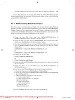
If the direction argument,
dir
, is 0 or not specified, then the event and timestep con-
trol occur on both positive and negative crossings of the signal. If the direction indica-
tor is +1 (-1), then the event and timestep control only occurs on positive (negative)
transitions of the signal. These cases are illustrated graphically in Figure 3.26. For
any other transitions of the signal, the
cross function does not generate an event.
Behavioral Descriptions
75
Please purchase PDF Split-Merge on www.verypdf.com to remove this watermark.
Behavioral Descriptions
The use of timetol is relevant for rapidly changing signals. If the cross analog
operator is used to delineate regions of behavior in the model, then valuetol crite-
ria can also be applied to define the appropriate level of accuracy.
The example Listing 3.19 illustrates a clocked sample-and-hold and how the cross
operator is used to set the sample value when the rising transition of the clock passes
through 2.5.
LISTING
3.19
Verilog-A definition of sample-and-hold based on cross.
module sah(out, in, clk);
output out;
input in, clk;
electrical out, in, clk;
real state = 0;
analog begin
76
Verilog-A HDL
Please purchase PDF Split-Merge on www.verypdf.com to remove this watermark.
Analog Events
@ (cross(V(clk) - 2.5, +1.0)) begin
state = V(in);
end
V(out) <+ transition(state, 1m, 0.1u);
end
endmodule
The analog event statement is specified such that it is triggered by a cross analog
operator when the value of its’ expression, V(clk) – 2.5, goes from positive to
negative.
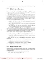
The 1 millisecond delay specified in the transition operator for the output signal,
is seen in the simulation results between the sample taken at the rising edge of the clk
signal passing through 2.5 volts shown in Figure 3.27.
The cross analog operator maintains internal state and thus has the same restrictions
as other analog operators.
Behavioral Descriptions
77
Please purchase PDF Split-Merge on www.verypdf.com to remove this watermark.
Behavioral Descriptions
3.5.2 Timer Event Analog Operator
The timer event analog operator is used to generate analog events to detect specific
points in time.
The timer event analog operator schedules an event that occurs at an absolute time
(as specified by the start). The analog simulator places a time point at, or just
beyond, the time of the event. If period is specified, then the timer function schedules
subsequent events at multiples of period.
For example, the following module uses the timer operator to generate a pseudo-
random bit sequence. To do this, a shift register of length m bits is clocked at some
fixed rate period as shown in Figure 3.29. An exclusive-OR of the m-th and n-th bits
form the input of the shift-register and the output is taken from the m-th bit.
78
Verilog-A HDL
Please purchase PDF Split-Merge on www.verypdf.com to remove this watermark.
Analog Events
In the definition of the behavior of the pseudo-random bit sequence generator, an inte-
ger array is used to represent the shift register and the exclusive-OR operation is done
using the (^) operator as shown in Listing 3.20.
LISTING 3.20 Verilog-A behavioral definition of pseudo-random bit stream
generator using the timer analog operator.
analog begin
@(timer(start, period)) begin
res = ireg[width - 1] ireg[tap];
for (i = width - 1 ;i>0;i=i-1) begin
ireg[i] = ireg[i - 1];
end
ireg[0] = res;
end
V(out) <+ transition(ireg[width-1], 1n, 1n, 1n);
end
The outputs of two pseudo-random bit sequence generators are shown in Figure 3.30
for a period
of
1
0
0n.
Behavioral Descriptions
79
Please purchase PDF Split-Merge on www.verypdf.com to remove this watermark.
Behavioral Descriptions
3.6 Additional Constructs
The Verilog-A language provides some additional behavioral constructs, especially
useful in the definition of high-level behavioral models. These include access to the
simulation environment, additional methods of formulating behaviors, and iterative
statements. Some of these have already been introduced indirectly, but will be dis-
cussed in more detail in this section.
3.6.1 Access to Simulation Environment
Access to the simulation environment can be necessary for describing behaviors that
can be dependent upon external simulation conditions. For example, the following
$
realtime()
$
temperature()
are Verilog-A defined system tasks that provide access to the conditions under which
the component is being evaluated. The $realtime() system tasks accesses the cur-
rent simulation time and allows custom independent sources to be defined in the lan-
guage. The ambient temperature, returned by the $temperature() system task, can
be used to define temperature dependent models such as semiconductor devices.
The modeler has some degree of control over the timesteps utilized during the course
of a transient simulation via use of the bound_step() function. The real-valued
argument to bound_step()indicates the maximum timestep that the module
requires for meeting its own accuracy constraints; the simulator can make a smaller
timestep based on its own accuracy constraints or those of other modules. An exam-
ple of the use of bound_step() is provided in Section 5.5 of the applications chap-
ter.
Additionally, it becomes useful to define behaviors conditionally upon the current
analysis. For this purpose, the analysis() function is provided. analysis()takes
a string argument that is a descriptor of the analysis type to test for. For example,
analysis(“dc”)
returns 1 during DC analysis, such as that prior to transient analysis in order to deter-
mine the initial operating point, and 0 otherwise. Similarly,
analysis(“tran”)
80
Verilog-A HDL
Please purchase PDF Split-Merge on www.verypdf.com to remove this watermark.
Additional Constructs
returns 1 during a transient analysis, and 0 otherwise. An example of the use of
analysis() for initial conditions is provided in an example of Section 3.6.2.
3.6.2 Indirect Contribution Statements
The probe-source formulation is the primary method of formulating analog behaviors.
It provides a clear and tractable description of inputs, outputs, and their relationships
in the module definition. However, in all cases it is not necessarily possible nor con-
venient to formulate behaviors as a function of the output signals. These cases occur
commonly while developing purely mathematical models or modeling multi-disci-
plinary components.
In these cases, the Verilog-A language provides the
indirect contribution statement.
The indirect contribution statement allows for the specification of a behavior in terms
of a condition that must be solved for (as opposed to defining an output). The indirect
contribution statement allows descriptions of an analog behavior that implicitly spec-
ifies a branch potential in
fixed-point
form. This does not require that behavioral rela-
tionships be formulated in terms of the outputs.
The general form of the indirect contribution statement is:
target : branch == f( signals );
Where target represents the desired output, branch can be either of the following:
An implicit branch such as
V(out)
.
A derivative of an implicit branch such as ddt
(V(out))
.
A integral of an implicit branch such as idt
(V(out))
.
As with contribution statements, f ( signals ) can be any combination of linear,
nonlinear, algebraic, or differential expressions of a modules input or output signals,
constants, and parameters. For example, the ideal op amp, in which the output is
driven to the voltage that results in the input voltage being zero. Using indirect contri-
bution assignments, the opamp model could be written
1
:
V(out) : V(in) == 0.0;
1.
The behavior can also be expressed in the probe-source formulation as: V(out) <+
V(
out
)+V(in)
;
Behavioral Descriptions
81
Please purchase PDF Split-Merge on www.verypdf.com to remove this watermark.
Behavioral Descriptions
which can be read as: "determine V (out) such that V(in)
==
0". The indirect
contribution statement indicates that the signal out should be driven with a voltage
source and the source voltage value should be solved such that the given equation is
satisfied. Any branches referenced in the equation are only probed and not driven.
For example, the following differential equation and initial condition has a known
solution of sin
Using indirect contribution statements, the behavior would be represented as:
LISTING 3.21
Indirect contribution statement example.
analog begin
if (analysis (“dc”))
V(dx) <+ w0;
else
V(dx
)
<+ ddt(v(x))
;
V(x) : ddt(V(dx)) == -w0*w0*V(x);
end
For DC (which includes transient analysis initialization), the signal dx is set to the
initial condition of w0 by using the analysis() function within the conditional of
the if-else statement. Note that the else statement branch of the if-else
statement contains a ddt operator. This is permissible because the analysis()
statement has static properties (refer to Section 3.4.8).
The contribution statements and indirect contribution statement modelling methodol-
ogies provide similar functionality. Use of one or the other depends upon the particu-
lar modelling task at hand. However, as a general rule, the two different
methodologies are not mixed.
82
Verilog-A HDL
Please purchase PDF Split-Merge on www.verypdf.com to remove this watermark.
Additional Constructs
3.6.3 Case Statements
As introduced in Section 3.3.5, the case statement is another statement-level con-
struct that allows for multi-way decision tests. The statement tests whether an expres-
sion matches one of a number of other expressions, and branches accordingly. The
case statement is generally used in the following form:
case (p1)
0: $strobe(“p1 == 0”);
1: $strobe(“p1 == 1”);
default: $strobe(“p1 == %d”, p1);
endcase
The expression within the case statement (p1) is evaluated and compared in the
exact order to the case items (0, 1, and default) in which they are given. Dur-
ing the linear search of the case items, if one of the case item expressions matches
the case expression given in parenthesis, then the statement associated with that
case item is executed. In this example, if p1 == 0 or p1 == 1, then we will print a
message corresponding to p1 being either 0 or 1.
If all comparisons fail, and the default item is given, then the default item
statement is executed. If the default statement is not given, and all of the compari-
sons fail, then none of the case item statements are executed. In the example, for any
case other than p1 being either 0 or 1, we print a message indicating the value of p1.
3.6.4 Iterative Statements
The Verilog-A language supports three kinds of iterative statements. These statements
provide a means of controlling the execution of a statement zero, one, or more times.
repeat executes <statement> a fixed number of times. Evaluation of the con-
stant loop_cnt_expr decides how many times a statement is executed.
repeat ( loop_cnt_expr )
<statement>
while
executes a <statement> until the loop_test_expr becomes false. If
the
loop_test_expr starts out false, the <statement> is not executed at all.
Behavioral Descriptions
83
Please purchase PDF Split-Merge on www.verypdf.com to remove this watermark.
Behavioral Descriptions
while ( loop_test_expr )
<statement>
for is an iterative construct that uses a loop variable.
for ( init_expr ; loop_test_expr ; post_expr )
<statement>
for controls execution of its associated statement(s) by a three-step process as fol-
lows:
Execute init_expr, or an assignment which is normally used to initialize an
integer that controls the number of times the <statement> is executed
Evaluate loop_test_expr - if the result is zero, the for-loop exits, and if it is
not zero, the for-loop executes the associated <statement>
Execute post_expr, or an assignment normally used to update the value of the
loop-control variable, then continue.
As the state associated with analog operators cannot be reliably maintained, analog
operators are not allowed in any of the three looping statements.
3.7 Developing Behavioral Models
For both novice and seasoned model developers, a methodology for developing and
validating behavioral models is essential. The process of developing a behavioral
model should provide for a development of an intuitive understanding of the model as
well as the system in which it will operate. In contrast to digital simulation which is
activity-directed and the signals that effect a model can be easily isolated, behavioral
models defined for analog simulation must account for the loading and timing (or lack
thereof) in the whole system.
3.7.1 Development Methodology
A methodology for developing behavioral models should encourage a process of step-
wise refinement from the concept, to implementation and validation of the model. The
conceptual stage involves developing an understanding of what the behavioral model
is to accomplish in terms of capabilities and performance and other specifications.
The formulation, preferably beginning from an existing model, is the factorization of
84
Verilog-A HDL
Please purchase PDF Split-Merge on www.verypdf.com to remove this watermark.
Developing Behavioral Models
that specification into structural and behavioral components and its actual implemen-
tation. Verification and/or validation of the model includes the development of test
benches that can be used to test the behavior of the module to the original specifica-
tions. The methodology and development used for verification and validation of the
model can also be applicable in the verification of the final circuit-level implementa-
tion.
3.7.2 System and Use Considerations
A module defined in a behavioral language such as Verilog-A can be used as a com-
ponent within different types of systems and this should be reflected in the verifica-
tion phase of the module. For example, developing a behavioral model for use as a
component within a library would require much more rigorous formulation, as well as
have more stringent criteria for validation, than a model developed strictly for use as a
component in one specific design.
Understanding the context of use can also help the model developer make appropriate
decisions for accuracy as well as for efficiency in simulation. The transition ana-
log operator, which converts a discrete input to a piece-wise linear output, is charac-
terized in terms of rise
(
tr
)
and fall
(
tf
)
times of the output.
pwl_output = transition(disc, td, tr, tf) ;
Using very small values for tr and tf, relative to the overall length of the simulation
can be very costly in terms of simulation time. Moreover, the resulting fast-changing
Behavioral Descriptions
85
Please purchase PDF Split-Merge on www.verypdf.com to remove this watermark.
Behavioral Descriptions
output will not necessarily reflect the physical system or the underlying implementa-
tion. Similar considerations can be made when defining the sensitivity of a a model to
its inputs as in the use of tolerances in the cross operator.
3.7.3 Style
One of the major benefits of HDL-based design is the ability to convey and reuse
designs that are represented at a high-level of abstraction. This ability to communi-
cate the design information effectively amongst a group of designers is enhanced by
adopting consistent and agreed-upon techniques of style for the development of mod-
els. For example, the following are some of the common denominators in the devel-
opment of behavioral models that are easily defined:
Port ordering convention (inputs first, then outputs or vice-versus).
Degree of parameterization of the model and naming conventions.
Use of the Verilog pre-processor for enabling consistency and code documentation
purposes.
Coding style (layout) conventions for the module definitions.
The basic underlying theme is to plan for model reuse.
86
Verilog-A HDL
Please purchase PDF Split-Merge on www.verypdf.com to remove this watermark.
CHAPTER
4
Declarations and
Structural Descriptions
4.1 Introduction
Structural definitions in the Verilog-A language are the primary mechanism by which
a hierarchical design methodology such as top-down is facilitated for analog and
mixed-signal designs. The Verilog-A language allows analog and mixed-signal sys-
tems to be described by a set of components or modules and the signals that intercon-
nect them. The connection of these modules is defined in terms of the parameters, as
well as the ports or connection points, declared within the module definitions. The
declaration of parameters and ports within the module definition define the interface.
The interface definition determines how the module will be instantiated as part of a
structural module definition or as a component within a Spice netlist.
This chapter overviews the parameter, port, local variable and signal declarations, as
well as module instantiations within the Verilog-A language. This chapter also looks
at how module definitions relate to their instantiations.
4.2
Module Overview
A module in the Verilog-A language represents the fundamental user-defined type. A
module definition can be an entire system, or only a component within a system. A
Declarations and Structural Descriptions
87
Please purchase PDF Split-Merge on www.verypdf.com to remove this watermark.
Declarations and Structural Descriptions
module definition can be an active component in the system in which it effects the
signals in the system, either dependently or independently. Conversely, a module can
be a passive component which only monitors activity in the system, performing func-
tions associated with test benches.
Other than adhering to the constructs of the Verilog-A language, there are no restric-
tions on the type of systems that can be represented and how the representation is
defined. Module descriptions can include any number and type of parameters, be an
entirely structural or behavioral description, or include aspects of both structure and
behavior.
The general constituents of a module definition include the interface declarations and
the contents. The interface declarations consist of both the port and parametric decla-
rations of the module. The module contents can be composed of structural instantia-
tions, behavioral relationships, or both. For illustration purposes, the Verilog-A
description for a phase-lock loop system is used as shown in Figure 4.1.
The corresponding Verilog-A definition of the system is listed in Listing 4.1.
LISTING 4.1 Verilog-A definition of VCO and PLL.
‘
include “std.va”
‘
include “const.va”
module
pd
(out, in1, in2);
inout out, in1, in2;
electrical out, in1, in2;
parameter real gain = 1.0;
88
Verilog-A HDL
Please purchase PDF Split-Merge on www.verypdf.com to remove this watermark.
Module Overview
analog
V(out) <+ gain*V(in1)*V(in2);
endmodule
module
lpf(l, r, gnd);
inout
l
, r, gnd;
electrical l, r, gnd;
parameter real res = 1k;
parameter real cap = 1u;
I(l, r) <+ V(l, r)/res;
I(r,gnd) <+ ddt(V(r, gnd)*cap);
endmodule
module vco(out, in);
inout out, in;
electrical out, in;
parameter real ampl = 1.0; // V
parameter real fc = 10.0k; // Hz
parameter real kv = 1.0k; // V/s
real freq_v; // local variable declaration
analog begin
freq_v = fc + kv*V(in);
V(out) < + ampl*sin(2*‘M_PI*idt(freq_v));
end
endmodule
// structural definition of the pll system
module pll(out, in, gnd);
inout out, in, gnd;
Declarations and Structural Descriptions
89
analog begin
end
Please purchase PDF Split-Merge on www.verypdf.com to remove this watermark.
Declarations and Structural Descriptions
electrical out, in, gnd;
electrical pdout, vcoout; // local signals
pd pd1(pdout, in, vcoout);
lpf 1pf1(pdout, out, gnd);
vco vco1(vcoout, out);
endmodule
The module definitions listed above consist of four primary components:
interface declarations (port and parameter declarations for all modules).
structural instantiations (module instantiations declared in the pll module).
local variable declarations (freq_v in the vco module).
behavioral relationships (vco constitutive relationship).
The module definition of the phase-locked loop (pll), declares (instantiates) the
phase detector (pd), low-pass filter (lpf), and voltage-controlled oscillator (vco)
components. The definition of the phase-locked loop module defines the connectivity
of the other components comprising the system. In addition, parameters specified at
one level in the hierarchy can be passed down to lower levels during instantiation.
The structural instantiation of components within the Verilog-A language is depen-
dent upon the nature of the interface port and parameter declarations of the module,
and the language constructs used for instantiation.
4.2.1 Introduction to Interface Declarations
The interface declarations for a module definition include both port and parameter
declarations. The port declarations define the type and direction of signals and indi-
cate how that component can be instantiated within a structural description. The
parameters to the module can be used to characterize both behavior and structure.
Analog signals in the Verilog-A language are defined in terms of the quantities com-
posing the signal. As described previously, the definition of a signal type is encapsu-
lated in the nature and discipline definitions and must be known before used
within a module definition. The following Verilog-A preprocessor construct is used to
90
Verilog-A HDL
Please purchase PDF Split-Merge on www.verypdf.com to remove this watermark.
Module Overview
include the standard definitions of signals and physical constants prior to the defini-
tion of any modules.
‘include "std.va"
‘include "const.va"
The vco uses the standard definition for electrical systems of the discipline of type
electrical for declaring the types of the ports.
module vco(out, in);
inout out, in;
electrical out, in;
The electrical discipline characterizes the type of the signals between compo-
nents in the system. This example declares the ports of the vco to be of types inout
(bidirectional) which is a characteristic of conservative systems.
Parameter declarations include both the name and default values. Parameters for the
vco, include the amplitude of the output sinusoid (ampl), the center frequency of the
oscillator (fc), and the conversion gain of the oscillator (kv), are declared by the fol-
lowing
1
:
parameter real ampl = 1.0; // V
parameter real fc = 10.0k; // Hz
parameter real kv = 1.0k; // V/s
For both port and parameter declarations, the order within the module definition is
significant as this defines how the module is instantiated within a hierarchical design.
These concepts will be expanded upon further in section 4.3.2.
4.2.2 Introduction to Local Declarations
The Verilog-A language supports local declarations of variables of type integer
and real, as well as analog signals. In the vco module, the line
real freq_v; // local variable declaration
declares a local variable freq_v for use within the module. Similarly, local signals,
or signals that do not appear within the modules port or connection list, are declared
1. The Verilog-A language specification extends the Verilog HDL specification to include
optional type specifiers on parameter declarations. This is described in Section 4.3.2.
Declarations and Structural Descriptions
91
Please purchase PDF Split-Merge on www.verypdf.com to remove this watermark.
Declarations and Structural Descriptions
in the same manner: a discipline type name followed by a list of one or more identifi-
ers of the signals. The difference between local and port signal declarations is that the
local signal declarations do not have directions associated with them. Local signals
are typically used for defining intermediate structure within the module or for higher-
order formulations of analog behaviors. In the pll module definition of Listing 4.1,
electrical pdout, vcout;
declares signals pdout and vcout that are local to the pll module and used only
for connecting the pll’s instantiated components.
4.2.3 Introduction to Structural Instantiations
The Verilog-A language supports hierarchical descriptions by allowing modules to be
embedded within other modules. Higher level modules create instances of lower-level
modules and communicate with them through input
,
output, and inout ports.
The pll module definition instantiates the modules pd, lpf, and vco via the decla-
ration statements:
pd pd1(in, pdout, vcout);
lpf lpf1(pdout, out, gnd);
vco vco1(vcoout, out);
For example, we instantiate one vco instance named vco1 within the pll module
definition.
The type and direction of the signals, as well as parameters, used within the instantia-
tion statements must be compatible with the respective declarations within the child
module definition(s). The assignment of the connections and parameters of child
modules is done via port and parameter association. The association can be done via
named association, which assigns an expression or signal in the parent module with
the parameter or signal name in the child module, or by positional association, which
assigns an expression or signal to the order of declaration of a parameter or signal in
the child module.
92
Verilog-A HDL
Please purchase PDF Split-Merge on www.verypdf.com to remove this watermark.
Module Interface Declarations
4.3 Module Interface Declarations
A module definition is enclosed between the keywords module and endmodule
,
in
which the identifier following the keyword module is the name of the module being
defined. For the vco module previously defined:
The optional list of ports specify an ordered list of the module’s ports. The order spec-
ified will be significant when instantiating the module. The identifiers in this list must
be declared with a discipline type defining the type of the signal and a directional
specifier such as input, output, and inout in declaration statements within the
module definition.
In addition to port declarations, module definitions can also optionally incorporate
declarations of parameters incorporating default values and optional range checks. As
with ports, the order of declaration can be significant when instantiating the module.
4.3.1 Port Signal Types and Directions
Ports provide a means of interconnecting instances of modules. For example, if a
module X instantiates module Y, the ports of module Y are associated with either the
ports or the internal signals of module X. Associating connections between modules
requires that both the type and the direction of the signals are compatible. The Ver-
ilog-A language requires that both the type and direction attributes be declared for
each of a modules’ port signals.
The Verilog-A language uses the discipline definition for the type of the declaration
for module ports (ports are also analog signals or nodes). Hence, the type of a mod-
ules’ ports are declared by giving their discipline type, followed by the list of
port identifiers as,
Declarations and Structural Descriptions
93
Please purchase PDF Split-Merge on www.verypdf.com to remove this watermark.
Declarations and Structural Descriptions
electrical out, in;
which declares two signals, out and in, of type electrical. The electrical
discipline must have been defined prior to its use in the declaration. In essentially all
cases, the definition of a discipline type comes from the standard include files,
‘
include “std.va”
which is read prior to any module definitions.
The direction of a port can be specified as input, output, or inout (bidirec-
tional)
1
. If the direction is specified as being an input port, then the module will
only monitor the signals at the port and not modify them. That is, within the module
the port can only be passed into other modules as input ports and the signals on the
ports can only be used in expressions. A signal declared as input cannot be used on
the left side of a contribution statement (as a source).
If the direction is specified as being an output port, then the module will only affect
the signals at the port, but not be affected by them. Thus, the port can be passed to
instances of other modules as output ports and the signals on the ports cannot be
used in expressions but can be used on the left side of a contribution statement.
Finally, ports that are declared as being inout or bidirectional are not subject to
these restrictions.The syntax for port directional declarations is illustrated by example
below:
module vco(out, in);
electrical out, in;
inout out, in;
Two signals, out and in, in the port list of the vco are declared of type electri-
cal. The syntax for the port direction specification follows that from the type of the
port signals.
If the direction of the port is not specified, it is taken to be bidirectional (inout). In
analog system modeling, a port, which is also a node, represents a point of physical
connection between modules of continuous-time descriptions obeying conservation-
law semantics. Thus, in most cases, the inout directional specifier is used. In mod-
1. The directional specifiers input, output, and inout are only relevant for signals
within the modules port list. Internal signals only require (allow) the type specifier or disci-
pline.
94
Verilog-A HDL
Please purchase PDF Split-Merge on www.verypdf.com to remove this watermark.
Module Interface Declarations
ule definitions in which signal-flow behavioral modeling is used, or when the direc-
tional specifiers are required as an documentation aid in a conservative description,
the unidirectional specifiers input and output are appropriate.
In Verilog HDL, there is a close association of the directionality specified for the ports
due to the activity-directed nature ofdigital simulation. In the Verilog-A language, for
analog simulation, the same degree of association does not exist as all analog signals
or unknowns in the analog system are solved for simultaneously.
Listing 4.2 and 4.3 provide examples of port declarations and their usage.
LISTING 4.2 Definition and usage of conservative signals
module conservative(p, n);
electrical p, n;
inout p, n;
// ports p, n used on both sides of contribution
analog
V(p, n) <+ I(p, n)*R;
endmodule
LISTING 4.3 Definition and usage of signal-flow signals.
module signal_flow(out, in);
voltage out, in;
output out;
input in;
parameter real gain = 1.0;
// out only used for source, in only for probe.
analog
V(out) < + gain*V(in);
endmodule
Declarations and Structural Descriptions
95
Please purchase PDF Split-Merge on www.verypdf.com to remove this watermark.
Declarations and Structural Descriptions
4.3.2 Parameter Declarations
Parameter declarations are extensions of the basic integer and real type declara-
tions supported by the Verilog-A language. Parameters differ in that parameter decla-
rations must have initialization or default value expressions. Parameters can be
modified via structural instantiation to have values that are different from those speci-
fied by the default value expression. In addition, parameters support an extended dec-
laration syntax for range checking which allow the model developer to define
acceptable ranges or values for the parameters. Specifying the valid range of values
that a parameter can be assigned to during instantiation allows the model developer
the ability to restrict the values for the parameters to insure proper and/or expected
use of the model.
The basic syntax of parameter declarations is illustrated below:
The parameter keyword can be followed by an optional type specification (real
or integer) prior to the parameter name (
p1
above). If a type of a parameter is not
specified, it is derived from the type of the value of the default value expression. If the
type of the parameter is specified, and the value of the default expression conflicts
with the declared type of the parameter, the value of the default expression is coerced
to the type of the parameter.
As parameters are considered constants
1
during the simulation. As constants, a
default value for the parameter must always be specified in its declaration. This also
infers that the parameter value can only be set during the instantiation of the module,
and hence it is illegal to modify their value at runtime.
1. Their values are know at elaboration or at the time of instantiation and do not change during
the course of the simulation.
96
Verilog-A HDL
Please purchase PDF Split-Merge on www.verypdf.com to remove this watermark.
Module Interface Declarations
The parameter declaration can contain optional specifications of the permissible range
of the values for that parameter. The range specification consists of a qualifier and a
range. The value of a parameter is checked against the range during instantiation, and
is not a runtime assertion check.
The qualifiers for the range specification include either from or exclude
.
If the
keyword from is used, the value of the parameter must be within the following
range. If the keyword exclude is used, the value of the parameter must be outside
of the specified range. For the range, the use of brackets for the lower bound specifier
(lb_spec) and upper-bound specifier (ub_spec), [ and ] respectively, indicate
inclusion of the end point lb or
ub
in the range. The use of parenthesis for the
lb_spec or ub_spec, ( and ) respectively, indicate exclusion of the end point lb
or
ub
from the valid range. It is possible to include one end point and not the other by
mixing inclusion/exclusion combinations of the range bound specifiers, such as [ ) or
( ]. In all cases, the first expression in the range must be numerically smaller than the
second expression in the range (lb < ub).
More than one range may be specified for inclusion or exclusion of values as legal
values for the parameter. The keyword inf may be used to indicate infinity for one or
the other bound if there is none. Examples of legal parameter declarations are shown
in Listing 4.4.
LISTING 4.4
Example parameter declarations
parameter real
p1 =
1.0
;
parameter real p2 = 1.0 from (0:inf);
parameter integer ip1 = 1 exclude
0;
parameter p3 = 1.0;
parameter real p4 = 1;
Declarations and Structural Descriptions
97
Please purchase PDF Split-Merge on www.verypdf.com to remove this watermark.
Declarations and Structural Descriptions
4.4
Local Declarations
Local declarations are variables and signals declared within the scope of a modules
definition. For variables in the Verilog-A language, this includes variables of types
integer and real. For signals, these can be of any defined discipline type.
Variable declarations in the Verilog-A language are similar to many programming
languages in that the type keyword is followed by a list of one or more identifiers. The
identifiers can be scalar or vector. Each variable identifier is initialized to zero, as ini-
tializer expressions for non-parameters is not allowed. For example,
LISTING 4.5 Illustration of local variable declarations.
module ex(out, in);
inout out, in;
electrical out, in;
parameter integer width = 4;
real x, y;
real d[0:width - 1];
electrical t1, t2;
endmodule
The first declaration, “real x, y;”, declares two real-type variables named x and
y. The second, “
real d[0:width - 1];”, declares a real-type vector with a left
bound of 0, and an upper bound of width - 1. The size of the vector d is parame-
terized by the parameter width and includes both the left-bound and right-bound
elements.
Signal declarations are similar in that the
discipline is treated as a user-defined
type. The declaration,
electrical t1, t2 ;
98
Verilog-A HDL
Please purchase PDF Split-Merge on www.verypdf.com to remove this watermark.
Module Instantiations
declares two signals of type electrical named t
1
and t2. These signals can be used in
the instantiation of components of a structural definition for the module (Section 4.5),
in defining internal structure for the module, or higher-order behavioral definitions.
4.5
Module Instantiations
A structural description in Verilog-A is any description in which a module instantiates
another module within the scope of its definition. A structural definition for the sys-
tem will define an explicit hierarchy in the design.
Instantiation allows one module to incorporate a copy of another module into itself by
instantiating it
1
. The module instantiation statement creates one or more named
instances of a defined module.
When one module instantiates another module, it can alter the values of any parame-
ters declared within the instantiated module. The common ways to alter parameter
values are:
Module instance parameter value assignment by order, which allows values to be
assigned in-line during module instantiation in the order of their declaration. This
is known as positional association of module parameters.
Module instance parameter value assignment by name, which allows values to be
assigned in-line during module instantiation by explicitly associating parameter
names with the overriding values. This is known as named association of module
parameters.
Similarly, for connections to the model, there are two ways to assign ports of the
instantiated module to the local connection points:
Module instance parameter value assignment by order, which allows values to be
assigned in-line during module instantiation in the order of their declaration (posi-
tional association).
Module instance parameter value assignment by name, which allows values to be
assigned in-line during module instantiation by explicitly associating parameter
names with the overriding values (named association).
1. A module definition does not contain the text of another module definition within its mod-
ule-endmodule keyword pair.
Declarations and Structural Descriptions
99
Please purchase PDF Split-Merge on www.verypdf.com to remove this watermark.