Tài liệu ANALOG BEHAVIORAL MODELING WITH THE VERILOG-A LANGUAGE- P6 doc
Bạn đang xem bản rút gọn của tài liệu. Xem và tải ngay bản đầy đủ của tài liệu tại đây (1.25 MB, 30 trang )
Voltage Regulator
180 degrees Celsius is shown in Figure 5.16. The “bow” in the voltage with respect to
temperature is a typical characteristic for bandgap based voltage reference.
Figure 5.17, shows the output voltage and the cell current as the supply voltage is var-
ied over the expected range of usage from 4 to 6 volts.
135
Please purchase PDF Split-Merge on www.verypdf.com to remove this watermark.
Figure 5.18, testing the dynamic response of models, verifies the output voltage as a
function of the switch current between the reference and the buffer amplifier.
Verilog-A HDL
136
Please purchase PDF Split-Merge on www.verypdf.com to remove this watermark.
QPSK Modulator/Demodulator
5.5 QPSK Modulator/Demodulator
Quadrature phase-shift keying, or QPSK, is an example of a modulation technique in
which the information carried within the signal is contained in the phase. The phase
of the signal can take on one of four values, such as shown in the constellation dia-
gram of Figure 5.19.
5.5.1 Modulator
As shown in the QPSK modulator schematic (Figure 5.20), the incoming binary
sequence is transformed into polar form by a nonreturn-to-zero (NRZ) encoder. Here,
the binary 1 and 0 symbols are transformed into +1 and -1 respectively. The NRZ data
stream is de-multiplexed into two separate binary sequences consisting of the odd-
and even-numbered input bits. These binary sequences are used to modulate a pair of
quadrature carriers, which are added together to produce the QPSK signal.
The QPSK modulator module consists of two primary components for the polariza-
tion of the input data sequence and the modulation of the quadrature components to
produce the QPSK signal. The modulator samples the input data stream (0s and 1s)
and converts it to the corresponding -1 or +1 every period seconds using the
timer operator. An integer variable
state
is toggled to convert the serial data
stream into two parallel streams for modulating the quadrature carriers.
LISTING 5.12
Verilog-A module definition of QPSK modulator
137
Please purchase PDF Split-Merge on www.verypdf.com to remove this watermark.
module qpsk_mod(out, in);
inout out, in;
electrical out, in;
parameter real offset = 0.0n;
parameter
real period = 100.0n;
parameter real oscfreq = 2
.
0e7;
real an, bn, bnm1;
integer state;
analog begin
@(timer(offset, period)) begin
if (state == 0) begin
an = (V(in) > 2.5) ? 1.0 : -1.0;
bn
=
bnm1;
end else begin
138
Verilog-A HDL
Please purchase PDF Split-Merge on www.verypdf.com to remove this watermark.
QPSK Modulator/Demodulator
bnm1 = (V(in) > 2.5) ? 1.0 : -1.0;
state = !state;
end
end
V(out) <+ (1.0/sqrt(2.0))*
(an*cos(2.0*`M_PI*oscfreq*$realtime()) +
bn*sin(2.0*`M_PI*oscfreq*$realtime()));
bound_step(0.05/oscfreq);
end
endmodul
e
To insure that an accurate representation of the QPSK signal is generated, the simula-
tion timestep is bounded to require a minimum of 20 points per oscillator period using
the bound_step function. The bound_step function acts to limit the timestep
utilized during the simulation. Its primary use is for the accurate generation of inde-
pendent sources such as the modulator. In this case,
bound_step
(0.
05/oscfreq);
limits the timestep used in the representation of the modulated signal to a minimum of
20 points per the period of the oscillator (Figure 5.21).
139
Please purchase PDF Split-Merge on www.verypdf.com to remove this watermark.
The output of the modulator (shown in Figure 5.22), shows the constant-envelope
modulator output with the phase transitions at the changes in the input data sequence.
5.5.2 Demodulator
The QPSK demodulator, shown in Figure 5.23, consists of a pair of correlators sup-
plied with a locally generated pairs of reference signals. The outputs of the correla-
tors, and are compared to a threshold of zero for their respective in-phase and
quadrature channel outputs. For the in-phase channel, if then a decision is
made in favor of symbol 1. Likewise, if then a decision is made in favor of the
symbol 0. A similar process occurs for the quadrature channel. The two binary
140
Verilog-A HDL
Please purchase PDF Split-Merge on www.verypdf.com to remove this watermark.
QPSK Modulator/Demodulator
sequences are combined in a parallel-to-serial converter to produce the original binary
input sequence.
LISTING 5.13 Verilog-A definition of QPSK demodulator.
module qpsk_demod(out, in);
inout out, in;
electrical out, in;
parameter real offset = 0.0n;
parameter real period = 100.0n;
parameter real oscfreq = 2.0e7;
real x_i, x_q;
real v_i, v_q;
real d_i, d_q;
real bout;
integer integreset;
integer state;
141
Please purchase PDF Split-Merge on www.verypdf.com to remove this watermark.
analog begin
v_i = V(in)*cos(2.0*`M_PI*oscfreq*$realtime());
v_q = V(in)*sin(2.0*`M_PI*oscfreq*$realtime());
integreset = 0;
@(timer(offset, period)) begin
integreset = 1;
d_i =
(x_i
>
0.0)
? 5.0 :
0.0;
d_q =
(x_q
>
0.0)
? 5.0 :
0.0;
end
x_i = idt(v_i, 0.0, integreset);
x_q = idt(v_q, 0.0, integreset);
@(timer(offset, period)) begin
if (state == 0) begin
bout = d_i;
end else begin
bout = d_q;
end
state = !state;
end
V(out) < + transition(bout, 1n, 1n, 1n);
end
endmodule
The timer analog operator is used to sample the output of the quadrature correlators at
the symbol period rate. The real variables x_i and x_q are used to store the correla-
tor outputs from the previous evaluation time. At the same time the correlator outputs
are sampled, the variable integreset is set to 1, causing the correlators to be reset
to the specified initial condition
(
0.0
)
.
integreset = 0;
@(timer(offset, period)) begin
integreset = 1;
d_i = (x_i > 0.0) ? 5.0 : 0.0;
d_q = (x_q > 0.0) ? 5.0 : 0.0;
end
142
Verilog-A HDL
Please purchase PDF Split-Merge on www.verypdf.com to remove this watermark.
5.6 Fractional N-Loop Frequency Synthesizer
This example illustrates design and analysis of a N.F frequency synthesizer, where N
is the integer multiple of the number and F is the fractional portion that the synthe-
sizer multiplies its input signal by.
143
Fractional N-Loop Frequency Synthesizer
x_i = idt(v_i, 0.0, integreset);
x_q = idt
(
v_q, 0.0, integreset);
A more detailed model of the demodulator would extract the timing information from
the incoming signal and use that to synchronize the symbol extraction.
Resetting the integrators at the symbol period implements an integrate-and-dump
algorithm for determining the symbol thresholds as shown in Figure 5.24.
Please purchase PDF Split-Merge on www.verypdf.com to remove this watermark.
The architecture, shown in Figure 5.25, consists of a divide-by-N frequency synthe-
sizer, augmented to provide fractional loop division. The fractional loop division is
carried out by removing pulses (module PR) prior to the divide-by-N counter which
feeds the phase detector. A pulse is removed whenever the accumulator (module
ACCUM) detects that the number of reference clock pulses times the fractional part
exceed one. To adjust for the phase error that occurs due to the missing pulses, the
accumulator generates an offset term that is summed in with the VCO control signal.
The structural definition of the fractional n-loop frequency synthesizer is shown
below.
The
resistor
and
capacitor
instantiations that constitute
the
low-pass
filter use simulator built-in primitives (see the test bench Listing 5.14 for their defini-
tions).
LISTING 5.14 Verilog-A definition for the structural module of the frequency
synthesizer.
‘
include "std.va"
‘
include "const.va"
Verilog-A HDL
144
module fnfs(out, in, gnd);
inout out, in, gnd;
electrical
out, in, gnd;
Please purchase PDF Split-Merge on www.verypdf.com to remove this watermark.
Fractional N-Loop Frequency Synthesizer
parameter
integer
n=1;
parameter integer
f=1;
accu #(.fract(f), .tdel(2n), .trise(2n), .tfall(2n))
xaccu(phase_offset, overflow, in);
fpd #(.tdel(2n), .trise(2n), .tfall(2n))
xpd(in, ndiv_out, inc, dec);
cp #(.cmag(.2m), .tdel(1n), .trise(5n), .tfall(5n))
xcp(inc, dec, filt_in, gnd) ;
sum
xsum(vco_in, filt_in, phase_offset);
dvco #(.fc(20e6), .gain(2e6), .tdel(10n), .
trise(2n), .tfall(2n)) xvco(vco_in, out);
pulrem #(.tdel(10n), .trise(2n), .tfall(2n))
xpulrem(rem_out, out, overflow);
divbyn #(.ratio(n))
xdivbyn(ndiv_out, rem_out);
capacitor #(.cap(50p)) c1(filt_in, comm);
resistor #(.resis(10k)) r1(comm, gnd);
capacitor #(.cap(5p)) c2(comm, gnd) ;
endmodule
5.6.1 Digital VCO
The digital vco defines a relationship between its input voltage and output frequency
as follows:
145
Please purchase PDF Split-Merge on www.verypdf.com to remove this watermark.
The algorithm used must have two discernible states that can be used to drive the vco
output. Consider the algorithm represented graphically in Figure 5.26.
The period,
T
, is defined by a full cycle of the integration - integrating the characteris-
tic equation from
0.0
to
0.5
and then back to
0.0
again. The direction of the inte-
gration
is set by the
variable
integ_dir
,
which
is
also used
to
define
the
output
(either
0
or
1
). The implementation of this algorithm for the
VCO
is shown in Listing
5.15.
LISTING 5.15 Verilog-A definition of the digital vco.
‘
include "std.va"
‘
include
"const.va"
‘
include "logic.va"
module dvco(in, out);
inout in, out;
electrical
in, out;
parameter real fc = 200.0;
parameter real gain = 1.0;
parameter real tdel = `LF_GATE_PROP_DELAY;
parameter
real
trise
= `LF_GATE_01_DRIVE_DELAY;
parameter real tfall = `LF_GATE_10_DRIVE_DELAY;
parameter
real vhigh = `LF_GATE_LOGIC_HIGH;
Verilog-A HDL
146
Please purchase PDF Split-Merge on www.verypdf.com to remove this watermark.
Fractional N-Loop Frequency Synthesizer
real
vout;
real period;
real integ_dir;
initial begin
integ_dir = 1.0;
end
analog begin
period = idt(integ_dir*(fc + kv*V(in));
// catch rising transition.
@(cross(period - 0.5, +1.0)) begin
integ_dir = -1.0;
end
// catch falling transition.
@(cross(period, -1.0)) begin
integ_dir = 1.0;
end
vout = 0.5*vhigh*(integ_dir + 1.0);
V(out) <+ transition(vout, tdel, trise, tfall);
end
endmodule
The
variable
period
is
used
to
store
the
value
of the
integral. Analog events
are
generated whenever the value of period crosses
0.5
in the positive or upward direc-
tion, or
0
.
0
in the negative or downward direction. At the generation of these events,
the
output
is
toggled
via the
integ_dir
variable,
and the
direction
of the
integra-
tion is reversed.
5.6.2 Pulse Remover
The pulse-removing module needs to monitor the overflow signal from the accumula-
tor in order to determine when to remove a pulse from the
vco
output prior to the
counter. A flag,
rn
, is used to determine when to signal that an overflow condition
has been received. This flag is checked on the next input transition - if set, that transi-
tion is effectively ignored. The use of a flag (versus direct clearing of the output
147
Please purchase PDF Split-Merge on www.verypdf.com to remove this watermark.
value) allows that an entire pulse will be removed, and not partial pulses. The imple-
mentation is shown in Listing 5.16.
LISTING 5.16 Verilog-A definition of pulse-remover
‘include "std.va"
‘include "const.va"
‘include "logic.va"
module pulrem(out, in, remove);
inout out, in, remove;
electrical out, in, remove;
parameter real tdel = ‘LF_GATE_PROP_DELAY;
parameter real trise = ‘LF_GATE_01_DRIVE_DELAY;
parameter real tfall = ‘LF_GATE_10_DRIVE_DELAY;
parameter real vthresh = ‘LF_MID_THRESH;
real vout_val = 0.0;
integer rn = 0;
analog begin
@(cross(V(in) - vthresh, +1.0)) begin
vout_val = (rn) ? 0.0 : 5.0;
rn = 0;
end
@(cross(V(in) - vthresh, -1.0)) begin
vout_val = 0.0;
end
// set the rn (remove_next) flag on positive
// transitions of the remove signal.
@(cross(V(remove) - vthresh, +1.0)) begin
rn
= 1 ;
end
V(out) <+ transition(vout_val, tdel, trise,
tfall) ;
end
endmodule
Verilog-A HDL
148
Please purchase PDF Split-Merge on www.verypdf.com to remove this watermark.
Fractional N-Loop Frequency Synthesizer
5.6.3 Phase-Error Adjustment
The accumulator module is used to both determine the removal of pulses from the vco
output for the control loop and to provide the phase-error correction voltage that is
required to offset the missing pulse. At each edge of the reference input, a summation
register
vsum
is incremented with the fractional loop value. When this value exceeds
the equivalent value of
1.0
, the overflow bit is set and
vsum
is set to the remainder.
The overflow bit is reset on the next clock cycle of the reference input.
LISTING 5.17 Verilog-A definition of phase adjustment accumulator
‘
include "std.va"
‘
include "const.va"
‘
include "logic.va"
module accu(sum, ovf, ref);
inout sum, ovf, ref;
electrical
sum, ovf, ref;
parameter real tdel = ‘LF_GATE_PROP_DELAY;
parameter real trise = ‘LF_GATE_01_DRIVE_DELAY;
parameter real tfall = ‘LF_GATE_10_DRIVE_DELAY;
parameter real vthresh
= ‘LF_MID_THRESH;
parameter real fract = 1.0;
parameter real scale = 1.0;
real vsum = 0.0;
real vovf = 0.0;
analog begin
@(cross(V(ref) - vthresh, +1.0)) begin
vsum = vsum + fract;
if (vovf > 0.0) begin
vovf = 0.0;
end
if (vsum > 10.0) begin
vsum = vsum - 10.0;
vovf = 5.0;
end
end
149
Please purchase PDF Split-Merge on www.verypdf.com to remove this watermark.
V(ovf) <+ transition(vovf, tdel, trise, tfall);
V(sum) <+ transition(0.1*scale*vsum, tdel,
trise, tfall);
end
endmodule
5.6.4 Test Bench and Results
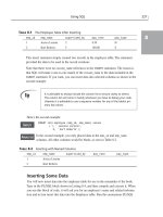
Listing 5.18 is the test bench designed for evaluating the system performance. The
input reference clock is 4MHz. The loop multiplication factor is set to 5.4 (N=5, F=4)
and thus the vco output frequency should be at 21.6MHz.
LISTING 5.18 Spice netlist of frequency synthesizer test bench.
* Fractional N-loop frequency synthesizer
.verilog "accu.va"
.verilog "cp.va"
.verilog
"dvco.va"
.verilog "divbyn.va"
.verilog "fnfs.va"
.verilog "fpd.va"
.verilog "pulrem.va"
.verilog "sum.va"
vref ref 0 dc 0 pulse(0 5 10n 2n 2n 100n 250n)
xfnfs out ref 0 fnfs n=5 f =4
.model capacitor c
.model resistor r
.tran .02u 10. 0u
.end
The test bench setup defines two model definitions (for resistor and capaci-
tor) which are simulator primitives instantiated from within the fnfs structural
description.
150
Verilog-A HDL
Please purchase PDF Split-Merge on www.verypdf.com to remove this watermark.
Fractional N-Loop Frequency Synthesizer
Figure 5.27 shows the dynamic characteristics of the
vco
input signal. The phase-
locked loop achieves lock after approximately five microseconds.
151
Please purchase PDF Split-Merge on www.verypdf.com to remove this watermark.
Figuire 5.28 shows the output signal after the
vco
acquires lock. Note, that for five
clock cycles of the reference signal, the output goes through 27 cycles (5.4 * 5).
152
Verilog-A HDL
Please purchase PDF Split-Merge on www.verypdf.com to remove this watermark.
Antenna Position Control System
5.7 Antenna Position Control System
This example illustrates some of the multi-disciplinary modeling capabilities of the
Verilog-A language. The antenna position control system, shown in Figure 5.29, con-
sists of both electrical and mechanical (rotational) components.
The position control system employs two potentiometers, one for converting the
external position control into a voltage and another for sensing the current position of
the antenna. The outputs of the potentiometers feed into a differential amplifier which
drives the motor. The antenna is driven by the output of the motor via a gearbox.
The potentiometers are defined in terms of electrical and rotational disci-
plines. The rotational discipline relates an angle to a torque and is used to sense
the position of the input shaft of the potentiometer. The motor, gearbox, and antenna
mechanical components are defined in terms of the rotational_omega discipline
which relates angular velocity to torque. Hence, we integrate the angular velocity of
the antenna to determine its position.
153
Please purchase PDF Split-Merge on www.verypdf.com to remove this watermark.
5.7.1 Potentiometer
The potentiometer model converts a rotational position into a voltage. The module is
parameterized in terms of the minimum and maximum values of the potentiometer
control shaft. The corresponding output voltage scale is controlled by the value of the
voltage across
the
input pins,
inPos
and
inNeg
.
LISTING 5.19
Verilog-A potentiometer definition.
module potentiometer(out, shaft, inPos, inNeg);
output out;
input shaft, inPos, inNeg;
electrical
out;
rotational
shaft;
electrical
inPos, inNeg;
parameter real min_angle = -‘M_PI;
parameter real max_angle = ‘M_PI;
real scale, shaft_angle;
analog begin
if (Theta(shaft) > max_theta)
shaft_angle = max_theta;
else if (Theta(shaft) < min_theta)
shaft_angle = min_theta;
else
shaft_angle
= Theta(shaft);
scale = V(inPos, inNeg)/(max_cntrl - min_cntrl);
V(out) <+ V(inNeg) + scale*ctrl_val;
end
endmodule
5.7.2 DC Motor
The core of any DC motor is an electrical armature which converts between electrical
and mechanical power without any loss. The electrical properties of the motor include
its resistance,
and inductance,
The mechanical properties are the motors iner-
154
Verilog-A HDL
Please purchase PDF Split-Merge on www.verypdf.com to remove this watermark.
Antenna Position Control System
tia, and rotational friction, The back voltage generated by the motor is
times the angular frequency of the motor, , and the torque is times the current
through the motor, This is shown diagrammatically in Figure 5.30.
The equations describing the terminal and output characteristics of the motor become:
Within the DC motor module, these equations representing the constitutive behavior
of the component are:
Tau(shaft) <+ Kt*I(in) - Bm*Omega(shaft) -
ddt(Jm*Omega(shaft));
V(in) <+ Rm*I(in) + ddt(Lm*I(in)) + Km*Ome
ga(shaft
)
;
5.7.3 Gearbox
The motor translates torque to the antenna via a gearbox. In addition to the transla-
tional affects of the gear ratios between the two shafts, the model for the gearbox
must be bidirectional in that the torque from the motor must affect the antenna, and
the inertial load of the antenna must be expressed on the load of the motor.
155
Please purchase PDF Split-Merge on www.verypdf.com to remove this watermark.
If we assume that the gears do not slip, then equating translational distance for the
two gears in terms of their angular position yields:
The relationship between the torque on the two shafts is related by the force at the
point of contact, where The total torque on the shaft is the exter-
nally applied torque less the inertia of the gear.
LISTING
5.20
Verilog-A gearbox model.
module gearbox(shaft1, shaft2);
inout shaft1, shaft2;
rotational_omega shaft1, shaft2;
parameter real r1 = 1 from (0:inf);
parameter real i1 = 1m from [0:inf);
parameter real r2 = 1 from (0:inf);
parameter real i2 = 1m from [0:inf);
analog begin
Omega(shaft1) <+ Omega(shaft2)*(r2/r1);
Tau(shaft2) < + i2*ddt(Omega(shaft2)) +
(Tau(shaft1) - i1*ddt(Omega(shaft1)))*r2/r1;
end
endmodule
5.7.4 Antenna
The antenna represents a rotational load on the shaft of the gearbox which is charac-
terized in terms of the inertia.
LISTING 5.21
Verilog-A antenna model.
module
antenna(shaft);
inout
shaft;
rotational_omega shaft;
parameter real i=1;
156
Verilog-A HDL
Please purchase PDF Split-Merge on www.verypdf.com to remove this watermark.
Antenna Position Control System
analog begin
Tau(shaft) <+ i*ddt(Omega(shaft));
end
endmodule
5.7.5 Test Bench and Results
The modules are assembled in the Listing 5.22 as per the schematic of Figure 5.31.
LISTING
5.22
Spice netlist of antenna position controller test bench
* position controller
.verilog “servo.va”
vsupply supply 0 5.0
vctrl inpos 0 pwl(0 0102 -1.0472
+ 10 -1.0472 11 0.7854 20 0.7854)
xinpot supply 0 inpos diffplus potentiometer
+ min_ctrl=-1.5708 max_ctrl=1.5708
xdiffamp inmotor diffplus diffminus diff_amp k = 24
xmotor inmotor outangle motor_dc
xgearbox outangle gearangle gearbox
+ r2=10 i1=0 i2=0
xantenna gearangle antenna inertia=1
xintgr8 igearpos gearangle intgr8 pos_ic = 0
xoutpot supply 0 igearpos diffminus potentiometer
+ min_ctrl = -1.5708 max_ctrl = 1.5708
.tran 0.01 20
.end
157
Please purchase PDF Split-Merge on www.verypdf.com to remove this watermark.
In Figure 5.31, we show the applied position to the control system and the response
for both light and heavy antennas. The position input to the system is in radians.
The applied voltage to the motor is shown in Figure 5.32
158
Verilog-A HDL
Please purchase PDF Split-Merge on www.verypdf.com to remove this watermark.
Lexical Conventions and
Compiler Directives
Appendix A
Verilog-A source files are a stream of lexical tokens. A lexical token consists of one
or more characters. The layout of tokens in a source file is free format - spaces and
newlines are not syntactically significant other than being token separators, except
escaped identifiers.
The types of lexical tokens in the language are as follows:
white space
comment
operators
number
string
identifier
keyword
A.1.1 White Space
White space contains the characters for spaces, tabs, newlines, and form feeds. These
characters are ignored except when they serve to separate other lexical tokens.
Lexical Conventions and Compiler Directives
159
A.1 Verilog-A Language Tokens
Please purchase PDF Split-Merge on www.verypdf.com to remove this watermark.