Tài liệu ANALOG BEHAVIORAL MODELING WITH THE VERILOG-A LANGUAGE- P7 docx
Bạn đang xem bản rút gọn của tài liệu. Xem và tải ngay bản đầy đủ của tài liệu tại đây (1.39 MB, 30 trang )
A.1.12 System Tasks and Functions
Compiler Directives
The (
$
) character introduces a language construct that enables development of user-
defined tasks and functions. A name following the (
$
) is interpreted as a system task
or a system function.
See Appendix B. for Verilog-A system tasks and their descriptions
All Verilog-A language compiler directives are preceded by the (
‘
) character. This
character is called accent grave. It is different from the character (
’
), which is the sin-
gle quote character. The scope of compiler directives extends from the point where it
is processed, across all files processed, to the point where another compiler directive
supersedes it or the processing completes.
The following compiler directives are available:
A.2.1 ‘define and ‘undef
The directive
‘
define creates a macro for text substitution. This directive can be
used both inside and outside module definitions. After a text macro is defined, it can
be used in the source description by using the (
‘
) character, followed by the macro
name. The compiler substitutes the text of the macro for the string
‘macro_name.
Lexical Conventions and Compiler Directives
165
A.2 Compiler Directives
‘
define
‘else
‘endif
‘ifdef
‘include
‘resetall
‘undef
Please purchase PDF Split-Merge on www.verypdf.com to remove this watermark.
All compiler directives are considered predefined macro names; it is illegal to rede-
fine a compiler directive as a macro name. A text macro can be defined with argu-
ments. This allows the macro to be customized for each individual use. An example
of the definition and use is illustrated below:
Lexical Conventions and Compiler Directives
‘define threshold 0.5
‘define pp_max(a,b) ((a > b) ? a : b)
@(cross(V(thr) -‘threshold, 0.0))
V(out) <+ ‘pp_max(V(in1), V(in2));
The macro text can be any arbitrary text specified on the same line as the text macro
name. If more than one line is necessary to specify the text, the newline must be pre-
ceded by a backslash (\). The first newline not preceded by a backslash will end the
macro text The newline preceded by a backslash is replaced in the expanded macro
with a newline (but without the preceding backslash character).
For an argument-less macro, the text is substituted “as-is” for every occurrence of the
‘text_macro. However, a text macro with one or more arguments must be expanded
by substituting each formal argument with the expression used as the actual argument
in the macro usage.
A.2.2 ‘ifdef, ‘else, ‘endif
These conditional compilation compiler directives are used to optionally include lines
of a Verilog-A language source description during compilation. The
‘
ifdef com-
piler directive checks for the definition of a variable name. If the variable name is
defined, then the lines following the ‘
ifdef
directive are included. If the variable
name is not defined and a
‘
else directive exists then this source is compiled.
These directives may appear anywhere in the Verilog-A source description.
166
Verilog-A HDL
An undefined text macro has no value.
The
directive
‘
undef undefines
a
previously
defined
text macro.
An
attempt
to
undefin
e
a text macro that was not previously defined using a ‘define compiler
directive can result in a warning.
Please purchase PDF Split-Merge on www.verypdf.com to remove this watermark.
Compiler Directives
The ‘ifdef, ‘else, ‘endif compiler directives work in the following manner:
When an ‘ifdef is encountered, the text macro name is test to see if it is defined
as a text macro name using ‘define within the Verilog-A language source
description
If the text macro name is defined, the first group of lines is compiled as a part of
the description. If there is an ‘else compiler directive, the second group of lines
is ignored.
If the text macro name has not been defined, the first group of lines is ignored. If
there is an ‘else compiler directive the second group of lines is compiled.
Any group of lines that the compiler ignore still must follow the Verilog-A language
lexical conventions for white space, comments, numbers, strings, identifiers, key-
words, and operators. The following are some examples of using the ‘ifdef and
‘
endif
compiler directives:
‘define debug
‘ifdef debug
$strobe(
“
module %m: input signal = %g at time %g
”
,
V(in), $realtime());
These compiler directives may be nested.
A.2.3 ‘include
The ‘include compiler directive is used to insert the entire contents of a source file
in another file during compilation. The result is as thought the contents of the
included source file appear in place of the ‘include compiler directive. The
‘include compiler directive can be used to include global or commonly used def-
initions and tasks without encapsulating repeated code within module boundaries. For
example:
‘include “std.va”
Includes the standard definitions for discipline and nature definitions into the
scope of the current file. The ‘include mechanism permits configuration management
and organization of Verilog-A source files.
Lexical Conventions and Compiler Directives
167
‘endif
Please purchase PDF Split-Merge on www.verypdf.com to remove this watermark.
Lexical Conventions and Compiler Directives
The compiler directive ‘include can be specified anywhere within the Verilog-A
language description. The filename is the name of the file to be included in the source
file. The filename can be a full or relative path name.
Only white space or a comment may appear on the same line as the ‘include com-
piler directive.
A file included in the source using the
‘
include compiler directive may contain
other
‘
include compiler directives. The number of nesting levels for included
may be limited, but the limit shall be at least 15.
A.2.4 ‘resetall
When the ‘reset_all compiler directive is encountered during compilation, all
compiler directives are set to the default values. This is useful for insuring that only
those directives that are desired in compiling a particular source file are active.
The recommend usage is to place ‘resetall at the beginning of each source text
file, followed immediately by the directives desired in the file.
168
Verilog-A HD
L
Please purchase PDF Split-Merge on www.verypdf.com to remove this watermark.
Appendix B
System Tasks and
Functions
B.1 Introduction
The Verilog-A language supports a variety of system tasks and functions. These tasks
and functions are useful for querying and controlling the current simulation as well as
displaying the results of the simulation as it progresses.
B.2 Strobe Task
The
$strobe task is the main task for printing information during a simulation.
$strobe
always prints a newline character at the end of its execution. The typical
form of the parameters to
$
strobe is:
$strobe("format specification", parameters)
The format control specification string defines how the following arguments in the
$strobe
task are to be printed. The syntax is a percent character (%) followed by a
System Tasks and Functions
169
Please purchase PDF Split-Merge on www.verypdf.com to remove this watermark.
System Tasks and Functions
format specifier letter. Allowable letters in the format control specification are shown
in the table below:
letter
display format
hexadecimal
decimal
octal
binary
ASCII character
string
hierarchical name
comments
takes no arguments
Other special characters may be used with escape sequences.
escape sequence
\n
\t
\\
\"
\ddd
display
new line character
tab character
the \ character
the " character
character specified in up to three octal digits
B.2.1 Examples
The following are examples on the use of the
$strobe
task:
$strobe("input = %g", V(in));
$strobe("result = %b", ~flag & bits);
$strobe("%m: event triggered at t = %g",
$
realtime
());
B.3 File Output
The $strobe task has a version for writing to files, $fstrobe
.
$fstrobe
requires an extra parameter, called the file descriptor, as shown below:
170 Verilog-A HDL
h
d
o
b
c
s
m
or
or
or
or
or
or
or
H
D
O
B
C
S
M
Please purchase PDF Split-Merge on www.verypdf.com to remove this watermark.
Simulation Time
$
fstrobe(descriptor, "format specification",
parameters)
The descriptor is an integer value returned from the $fopen function. $fopen
takes the form:
integer fdescriptor;
fdescriptor = $fopen("file_name");
$fopen will return a 0 if it was unable to open the file for writing. When finished,
the file can be closed with the $fclose function call:
$fclose(fdescriptor)
;
The file descriptors are set up so that each bit of the descriptor indicates a different
channel. Thus, multiple calls to $fopen will return a different bit set. The least sig-
nificant bit indicates the "standard output". By passing the bit-wise or of two or more
file descriptors to $fstrobe, the same message will be printed into all of the files
(as well as standard output) indicated by the or-ed file descriptors.
B.4 Simulation Time
$realtime is a system task that returns the current simulation time as a real
number.
$realtime()
B.5 Probabilistic Distribution
The probabilistic distribution functions return pseudo-random numbers whose char-
acteristics are described by the task name.
$dist_uniform(seed, start, end)
$dist_normal(seed, mean, standard_deviation)
$dist_exponential(seed, mean)
$dist_poisson(seed, mean)
System Tasks and Functions
171
Please purchase PDF Split-Merge on www.verypdf.com to remove this watermark.
System Tasks and Functions
$
dist_chi_square
(seed, degree_of_freedom)
All of the parameter are integer values and all return real values. For each system
task, the
seed
parameter must also be an integer variable that is initialized by the
user and only updated by the system task.
The $dist_uniform returns random numbers uniformly distributed in the interval
specified by its parameters.
For the $ dist_normal and $ dist_chi_square functions, the
standard_deviation
and
degree_of_freedom
parameter respectively are
used to determine the shape of the density functions. With a mean of 0 and
standard_deviation
of 1,
$
dist_normal generates a gaussian distribution.
For $dist_chi_square, larger numbers will spread the returned values over a
wider range.
For $ dist_exponential and $ dist_poisson, the mean parameter is an inte-
ger which causes the average value returned by the function to approach the value
specified.
B.6 Random
The $random system function provides a random number mechanism, returning a
new 32-bit random number each time the function is called. The returned value is a
signed integer; it can be positive or negative. The function may be called with or
without a seed parameter.
$random
$random(seed)
The
seed
parameter is used to initialize the stream of numbers that
$
random
returns.
The
seed
parameter must
be a
integer variable
and
assigned
a
value before
calling $random.
172
Verilog-A HDL
Please purchase PDF Split-Merge on www.verypdf.com to remove this watermark.
Simulation Environment
B. 7 Simulation Environment
These functions return information about the current simulation environment parame-
ters. All return a real number.
System Tasks and Functions
173
Please purchase PDF Split-Merge on www.verypdf.com to remove this watermark.
Laplace and Discrete
Filters
Appendix C
C.1 Introduction
The laplace and discrete transform analog operators in the Verilog-A language allow
for specification of the filter coefficients in four different combinations of either poly-
nomial or zeros/poles for the numerator and denominator of the filter.
This appendix describes these forms in detail, as well as presenting some MATLAB
scripts for generating the required coefficients from filter specifications. (MATLAB is
a registered trademark of the MathWorks, Inc., 24 Prime Park Way, Natick, MA
01760-1500: telephone (508) 653-1415, Fax (508) 653-2997, e-mail: info@math-
works.com). These scripts may require the Simulink Toolkit.
C.2 Laplace Filters
C.2.1 laplace_zp
laplace_zp implements the zero-pole form of the Laplace transform filter.
Laplace and Discrete Filters
175
Please purchase PDF Split-Merge on www.verypdf.com to remove this watermark.
Laplace and Discrete Filters
where is a vector of M paris of real numbers. Each pair represents a zero, the first
number in the pair is the real part of the zero, and the second is the imaginary part.
Similarly, is the vector of N real pairs, one for each pole. The poles are given in the
same manner as the zeros. The transfer function is:
where and are the real and imaginary parts of the zero, while and
are the real and imaginary parts of the
pole. If a root (a pole or a zero) is
real, the imaginary part must be specified as 0. If a root is complex, its conjugate must
also be present. If a root is zero, then the term associated with it is implemented as s
rather than (1 – s / r
)
where r is the root.
C.2.2 laplace_zd
laplace_zd implements the zero-denominator form of the Laplace transform filter.
where is a vector of M paris of real numbers. Each pair represents a zero, the first
number in the pair is the real part of the zero, and the second is the imaginary part.
Similarly, d is the vector of N real coefficients of the denominator. The transfer func-
tion is:
where and are the real and imaginary parts of the zero, while is the
power of s in the denominator. If a zero is real, the imaginary part must be spec-
176
Verilog-A HDL
Please purchase PDF Split-Merge on www.verypdf.com to remove this watermark.
Laplace Filters
ified as 0. If a zero is complex, its conjugate must also be present. If a zero is zero,
then the term associated with it is implemented as s rather than
C.2.3 laplace_np
laplace_np
implements the numerator-pole form of the Laplace transform filter.
where is a vector of M real numbers that contains the coefficients of the numerator.
For the denominator, is the vector of N real pairs, one for each pole where the first
number in the pair is the real part of the zero, and the second is the imaginary part.
The transfer function is:
where is the coefficient of the
power of s in the numerator, while and
are the real and imaginary parts of the pole. If the pole is real, the imaginary
part must be specified as 0. If a pole is complex, its conjugate must also be present. If
a pole is zero, then the term associated with it is implemented as s rather than
C.2.4 laplace_nd
laplace_nd implements the numerator-denominator form of the Laplace trans-
form filter.
laplaca_nd(expr, n, d
)
where n is a vector of M real numbers that contains the coefficients of the numerator,
and d is a vector of N real numbers that contains the coefficients of the denominator.
The transfer function is:
Laplace and Discrete Filters
177
Please purchase PDF Split-Merge on www.verypdf.com to remove this watermark.
Laplace and Discrete Filters
where is the coefficient of the power of s in the numerator, and is the
coefficient of the power of s in the denominator.
C.3 Discrete Filters
C.3.1 zi_zp
zi_zp implements the zero-pole form of the Z transform filter.
where is a vector of M paris of real numbers. Each pair represents a zero, the first
number in the pair is the real part of the zero, and the second is the imaginary part.
Similarly,
is the vector of N real pairs, one for each pole. The poles are given in the
same manner as the zeros. The transfer function is:
where and are the real and imaginary parts of the zero,while and
are the real and imaginary parts of the pole. If a root (a pole or a zero) is
real, the imaginary part must be specified as 0. If a root is complex, its conjugate must
also be present. If a root is zero, then the term associated with it is implemented as
rather than where r is the root
178
Verilog-A HDL
Please purchase PDF Split-Merge on www.verypdf.com to remove this watermark.
Discrete Filters
C.3.2 zi_zd
zi_zd implements the zero-denominator form of the Z transform filter.
where is a vector of M paris of real numbers. Each pair represents a zero, the first
number in the pair is the real part of the zero, and the second is the imaginary part.
Similarly, d is the vector of N real coefficients of the denominator. The transfer func-
tion is:
where and are the real and imaginary parts of the zero, while is the
power of s in the denominator. If a zero is real, the imaginary part must be spec-
ified as 0. If a zero is complex, its conjugate must also be present. If a zero is zero,
then the term associated with it is implemented as rather than
C.3.3 zi_np
zi_np implements the numerator-pole form of the Z transform filter.
where n is a vector of M real numbers that contains the coefficients of the numerator.
For the denominator, is the vector of N real pairs, one for each pole where the first
number in the pair is the real part of the zero, and the second is the imaginary part.
The transfer function is:
where is the coefficient of the power of s in the numerator, while and
are the real and imaginary parts of the pole. If the pole is real, the imaginary
part must be specified as 0. If a pole is complex, its conjugate must also be present. If
Laplace and Discrete Filters
179
Please purchase PDF Split-Merge on www.verypdf.com to remove this watermark.
Laplace and Discrete Filters
a pole is zero, then the term associated with it is implemented as rather than
C.3.4 zi_nd
zi_nd implements the numerator-denominator form of the Z transform filter.
where
n
is a vector of M real numbers that contains the coefficients of the numerator,
and
d
is a vector of N real numbers that contains the coefficients of the denominator.
The transfer function is:
zi_nd(expr, n, d, T
)
where is the coefficient of the power of in the numerator,
and is the
coefficient of the power of in the denominator.
180
Verilog-A HDL
Please purchase PDF Split-Merge on www.verypdf.com to remove this watermark.
Verilog-A MATLAB Filter Specification Scripts
C.4 Verilog-A MATLAB Filter Specification Scripts
The following MATLAB scripts for generating Verilog-A laplace and discrete filter
coefficients from the filter characteristics. Scripts are provided for Butterworth, Che-
byshev Type I and II, and Elliptic filters for both continuous and discrete time filters.
The Verilog-A MATLAB filter scripts are found in the MATLAB subdirectory on the
Verilog-A Explorer distribution diskette.
For laplace filters, there are four nnMATLAB scripts:
laplace_butter(fname, fpass, fstop, apass, astop);
laplace_cheby1(fname, fpass, fstop, apass, astop)
laplace_cheby2(fname, fpass, fstop, apass, astop)
laplace_ellip(fname, fpass, fstop, apass, astop)
Discrete filters in Verilog-A are specified:
zi_butter(fname, samp_freq, fpass, fstop, apass, astop,
tau,
t0)
zi_cheby1(fname, samp_freq, fpass, fstop, apass, astop,
tau,
t0)
zi_cheby2(fname, samp_freq, fpass, fstop, apass, astop,
tau,
t0)
zi_ellip(fname, samp_freq, fpass, fstop, apass, astop,
tau,
t0)
Both laplace and discrete filters accept the following arguments:
filter_name - name of the Verilog-A filter module.
fpass - passband corner frequency or cutoff frequency.
fstop - stopband corner frequency.
apass - passband attenuation in dBs. Maximum passband ripple or loss.
astop - stopband attenuation in dBs. Amount the stopband is down from the
passband.
In addition, the discrete filters take the following arguments:
samp_freq - sampling frequency of the filter.
Laplace and Discrete Filters
181
Please purchase PDF Split-Merge on www.verypdf.com to remove this watermark.
Laplace and Discrete Filters
tau - filter output transition time.
t0 - initial delay to the filter output.
The type of the filter is specified by the relationship of the passband to corner fre-
quencies. For lowpass filters, fpass is less than fstop:
A lowpass example:
laplace_cheby1(‘filter_1p’, 18000, 22000, 10, 60);
For highpass filters, fpass is greater than fstop
A highpass example:
182
Verilog-A HDL
Please purchase PDF Split-Merge on www.verypdf.com to remove this watermark.
Verilog-A MATLAB Filter Specification Scripts
laplace_cheby1(‘filter_hp
'
, 22000, 18000, 10, 60);
For bandpass and bandstop filters, fpass and fstop are two-element vectors that
specify the corner frequencies at both edges of the filter, lower frequency edge first.
A bandpass example:
laplace_cheby1(‘filter_bp’, [17750 18250],
[17500 18500], 3, 90);
For bandstop:
Laplace and Discrete Filters
183
Please purchase PDF Split-Merge on www.verypdf.com to remove this watermark.
184
Laplace and Discrete Filters
laplace_cheby1(‘filter_bs’, [17500 18500],
[17750 18250], 3, 90);
Verilog-A HDL
Please purchase PDF Split-Merge on www.verypdf.com to remove this watermark.
D.1 Introduction
The Verilog-A Explorer IDE (Integrated Development Environment) is a Windows
‘95/NT application targeted for designers and modelers wishing to learn analog
behavioral modeling with the Verilog-A language. The application includes:
Graphical user interface for language-based design entry and analysis
Spice-SL, a Spice3f5-based
1
simulator with the Verilog-A language compiler inte-
grated
Example circuits and sample Verilog-A modules
The Verilog-A Explorer user interface (Figure D.1) consists of thee major sections:
Project Navigator which allows interactive navigation of the design via the simu-
lation output results database
Workspace for editing of both circuit (
* .
ckt) and Verilog-A (
*.
va
) files
1. The simulator is a limited capability demonstration version in terms of capacity, compo-
nents, and analysis types supported.
Appendix D
Verilog-A Explorer IDE
Verilog-A Explorer IDE
185
Please purchase PDF Split-Merge on www.verypdf.com to remove this watermark.
Verilog-A Explorer IDE
Simulation Output Window for viewing the output results of the simulation.
All evaluation and analysis of Verilog-A designs within the Verilog-A Explorer envi-
ronment is centered around standard Spice circuit files. The circuit files include fea-
tures of:
Standard Spice syntax for design description and simulation control.
. verilog extension for incorporating Verilog-A module descriptions within the
circuit or test-bench description.
Instantiation of Verilog-A modules via standard subcircuit instantiations (standard
Spice Xxxxx device card).
186
Verilog-A HDL
Please purchase PDF Split-Merge on www.verypdf.com to remove this watermark.
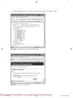
Installation and Setup
D.2 Installation and Setup
Running a:\setup from the distribution media results in the following setup dia-
log. Choose the installation directory (<install_dir>) if you would like to
change the path from the default (c:\veriloga)
D.2.1 Overview of the Distribution
After successful installation, under
<install_dir>
you will find the following
directory structure and files:
File license
.
txt
.
Directory bin executables for the IDE and simulator.
Directory book contains selected examples from the book.
Directory examples contains miscellaneous examples.
Directory include contains the Verilog-A standard definitions for disciplines
and physical constants.
Directory lib is organized in subdirectories for behavioral models of analog,
communications, data acquisition, and digital. Circuit test bench files are also
included.
Directory matlab includes the MATLAB scripts referenced in Appendix C.
Directory template has the template files for new * . ckt and *.va files cre-
ated from the Explorer IDE.
Directory tutorial contains the behavioral models and circuit used for illustra-
tion in this Appendix.
Verilog-A Explorer IDE
187
Please purchase PDF Split-Merge on www.verypdf.com to remove this watermark.
Verilog-A Explorer IDE
D.2.2 Executable and Include Path Setup
From the program group that is created, you can check the installation by starting the
Verilog-A Explorer IDE. From the Design->Settings menu (from the main menu bar),
raise the Settings dialog:
The Settings dialog includes information regarding paths to the Verilog-A Explorer
executables and include directories. These properties are defined as follows:
Executable: Path to the Spice simulator (should be:
<install_dir>\bin\spicesl.exe)
Output Directory: Path to top-level directory where the results directory will be
created. The default output directory is the path of the input circuit file. Change
this to point to an area where you would like all the simulation results to be stored.
Maintaining a common output directory can help with the organization (and dele-
tion) of unneeded results directories.
Verilog-A Preprocessor Definitions: A comma-separated list of Verilog-A prepro-
cessor directives to be passed to the Verilog-A language compiler. An identifier,
var, on this line is passed to the Verilog-A compiler with the same effect as
‘define var in the Verilog-A source.
Verilog-A Preprocessor Include Directory: Path to a comma-separated list of stan-
dard (for “std.va” and “const.va
”
definition files) and user-defined include
directories (should at least have <install_dir>\include for the standard
include files). If you maintain your own Verilog-A module libraries in a separate
directory, add a path to that directory here.
188
Verilog-A HDL
Please purchase PDF Split-Merge on www.verypdf.com to remove this watermark.
Installation and Setup
D.2.3 Overview of the IDE Organization
The organization of the Verilog-A Explorer IDE is centered around the input circuit
file
(* . ckt). The files containing the Verilog-A module definitions (* . va for the
environment
)
are referenced from the circuit file with the .verilog statement. For
example
,
the circuit file exp.ckt of Figure D.4 references two Verilog-A files,
file1.va and file2.va. When the Spice-SL simulator processes the input cir-
cuit file, it will pass these files off to the Verilog-A compiler.
A Verilog-A file can contain one or more definitions of Verilog-A modules. In essen-
tially all cases, module files include at least the standard discipline definitions file,
“
std.va
”,
as
well
as a file of
pre-defined physical constants,
“
const.va
”,
as
shown in Listing D.1.
LISTING D.1 Inclusion of standard discipline and constants definitions
Verilog-A Explorer IDE
189
‘include “ std.va
"
‘
include “cons t.va
"
Please purchase PDF Split-Merge on www.verypdf.com to remove this watermark.
Verilog-A Explorer IDE
Within the circuit file, instantiations of Verilog-A modules is done via an extension of
the Spice subcircuit instantiation mechanism. The subcircuit is instantiated as a ‘X’
device, as part of the instance name. Followed are the circuit nodes attached to the
module in the order as defined in the modules’ port list. The Verilog-A module name
identifies the type of the module, followed by an optional list of parameter-value
pairs.
Simulation of a circuit file creates a results directory that stores the output results for
all the analyses specified within the circuit file. The name of the results directory cre-
ated is the same as the circuit file but with a . res extension. When you are asked to
specify a results directory, it is this name. For example, in Figure D.5, exp.res is
the name of the results directory.
190
Verilog-A HDL
Please purchase PDF Split-Merge on www.verypdf.com to remove this watermark.