Nghiên cứu thiết kế chế tạo máy thu vệ tinh bằng tần c dùng trong truyền dẫn thông tin vệ tinh VINASAT
Bạn đang xem bản rút gọn của tài liệu. Xem và tải ngay bản đầy đủ của tài liệu tại đây (338.25 KB, 13 trang )
Nghiên cứu thiết kế chế tạo máy thu vệ tinh
bằng tần C dùng trong truyền dẫn thông tin vệ
tinh VINASAT
Nguyễn Đức Hùng
Trường Đại học Khoa học Tự nhiên
Khoa Vật lý
Luận văn Thạc sĩ ngành: Vật lý vô tuyến và điện tử; Mã số: 60 44 03
Người hướng dẫn: PGS.TS. Bạch Gia Dương
Năm bảo vệ: 2012
Abstract. Tìm hiểu tổng quan về hệ thống thu phát thông tin vệ tinh. Tìm hiểu về kỹ
thuật siêu cao tần: lý thuyết đường truyền; đồ thị smith; một số phương pháp phối
hợp trở kháng cơ bản. Nghiên cứu, thiết kế, chế tạo module khuếch đại tạp âm thấp
băng C.
Keywords. Thông tin vệ tinh; Kỹ thuật truyền thông; Máy thu; Vệ tinh Vinasat; Vật
lý vô tuyến
Content
Cùng với sự phát triển mạnh mẽ của khoa học kỹ thuật, thông tin vô tuyến bằng vệ tinh ra
đời và phát triển nhằm mục đích cải thiện các nhược điểm của mạng vô tuyến mặt đất, đạt
được dung lượng cao hơn, băng tần rộng hơn, nó có ý nghĩa chính trị, kinh tế xã hội to lớn,
đem lại dịch vụ mới và thuận tiện với chi phí thấp. Hiện nay ở Việt Nam ngành công nghệ vũ
trụ đang được đầu tư nghiên cứu, đây là hướng đi mới, mở ra nhiều lợi ích to lớn cho đất
nước. Trong thông tin vệ tinh các bộ thu phát đóng vai trò rất quan trọng, đây là bộ phận ảnh
hưởng chính đến chất lượng tín hiệu vệ tinh.
Để chế tạo máy thu vệ tinh băng tần C ta cần thiết kế bộ khuếch đại tạp âm thấp có hệ số
khuếch đại lớn hơn 10dB, tần số hoạt động từ 3.4 đến 3.7GHz
Sơ đồ khối hệ thống thu tín hiệu
Mạch dải siêu cao tần
Chúng ta đã biết, ở dải sóng vô tuyến điện thông thường: dài, trung, ngắn; các mạch dao
động cộng hưởng thường được xây dựng từ các phần tử tập trung như tụ điện C và cuộn cảm
L. Mạch dao động này cho tần số cộng hưởng riêng là:
LC2
1
f
0
Nhưng ở dải siêu cao tần thì mạch dao động (LC) từ các tham số tập trung không còn làm
việc được.
Thứ nhất: Để nhận được dải tần số cộng hưởng f
0
lớn hay bước sóng cộng hưởng nhỏ, ta
phải giảm các giá trị L, C đến mức tối thiểu. Nhưng việc giảm này cũng có những giới hạn
nhất định do kết cấu của tụ điện và cuộn cảm. Nên về nguyên tắc không đạt được tần số cộng
hưởng ở các dải song cao như cm và mm.
Thứ hai: ở dải song siêu cao tần, kích thước hình học của các tụ điện và cuộn cảm so sánh
với bước sóng điện từ, nên tại các tần số này bản thân mạch dao động cũng đóng vai trò như
phần tử bức xạ năng lượng điện từ làm tiêu hao năng lượng đáng kể trong mạch và mạch
không duy trì được dao động trong dải này.
Thứ ba: Trong dải siêu cao tần, khi tần số tăng thì tiêu hao do hiệu ứng bề mặt và tiêu hao
trong điện môi của cuộn cảm và tụ điện tăng đáng kể, làm giảm phẩm chất rõ rệt của mạch
dao động LC, làm cho nó mất tính chọn lọc của mạch cộng hưởng.
Vì vậy, ở dải sóng siêu cao tần, người ta sử dụng các mạch dao động có tham số phân bố,
thường được gọi là hộp cộng hưởng.
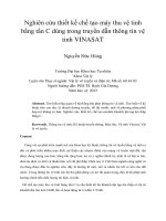
Phối hợp trở kháng dùng một dây nhánh
Phối hợp trở kháng bằng dây nhánh là phương pháp được sử dụng khá phổ biến do
đơn giản và dễ điều chỉnh. Có thể mắc dây nhánh vào đường truyền theo sơ đồ song song
hoặc nối tiếp với đoạn dây hở mạch hoặc ngắn mạch
Y
L
Y
0
d
A
A
Y
0
Z
L
Z
0
A
A
d
Z
0
Z
0
l
Y
0
l
(a) (b)
Phối hợp trở kháng bằng các đoạn dây nhánh
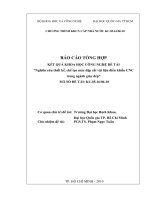
Phối hợp trở kháng dùng hai dây nhánh
Phương pháp phối hợp trở kháng bằng một dây nhánh có ưu điểm là đơn giản và có
thể sử dụng để phối hợp cho mọi trường hợp trở kháng đặc trưng của tải có phần thực khác 0.
Tuy nhiên nhược điểm của nó là sử dụng một đoạn đường truyền có độ dài biến đổi đặt giữa
tải và dây nhánh. Trong một số trường hợp chúng ta sử dụng phương pháp phối hợp trở
kháng dùng 2 dây nhánh nằm cách nhau một đoạn cố định. Tuy nhiên phương pháp này
không thể sử dụng cho mọi trường hợp của trở kháng tải.
Sơ đồ phối hợp trở kháng dùng 2 đây nhánh được mô tả ở Hình 2a, trong đó tải có thể
nằm cách dây nhánh đầu tiên một khoảng bất kì. Tuy nhiên, trong thực tế chúng ta thường sử
dụng sơ đồ Hình 2b, với tải đặt ngay sát dây nhánh thứ nhất. Sơ đồ 3.9b thường dễ thực hiện
hơn mà vẫn không làm mất tính tổng quát của bài toán. Hai dây nhánh sử dụng trong sơ đồ
hình 2 là 2 dây nhánh song song vì chúng có thể được thực hiện đơn giản hơn các dây nhánh
nối tiếp tuy nhiên về mặt lý thuyết các dây nhánh nối tiếp hoàn toàn có thể sử dụng để phối
hợp trở kháng bằng phương pháp này. Các dây nhánh có thể hở mạch hoặc ngắn mạch.
Sơ đồ phối hợp trở kháng sử dụng 2 dây nhánh song song
THỰC NGHIỆM
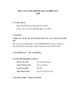
Nghiên cứu, thiết kế, chế tạo bộ khuếch đại tạp âm thấp (LNA)
Yêu cầu: Thiết kế bộ khuếch đại tạp âm thấp có hệ số khuếch đại lớn hơn 10dB, tần số hoạt
động từ 3.4 đến 3.7GHz.
Ý tưởng thiết kế: Để tính toán, cân đối giữa hệ số tạp âm và hệ số khuyếch đại thì cần có các
tham số như: , nhưng do chưa có thiết bị đo các tham số này theo tần số mong
muốn, mặt khác chúng ta có thể lựa chọn sử dụng transistor có tạp âm nền thấp. Linh kiện
được sử dụng là PHEMT GaAs FET SPF-2086T, đây là linh kiện có hệ số khuếch đại lớn, hệ
số tạp âm thấp. Để đạt được hệ số khuếch đại lớn nhất cần phải phối hợp trở kháng đầu vào
và đầu ra. Trong phần này, em thực hiện phối hợp trở kháng dùng công nghệ mạch dải (dây
nhánh và lamda/4)
Chip cao tần SPF-2086T
Chip cao tần SPF-2086T là chip có dải tần hoạt động rộng, hệ số khuếch đại lớn, phù hợp
với việc thiết kế, chế tạo các bộ khuếch đại tạp âm thấp.
Tần số GHz
Hệ số khuếch đại dB
3.491
10.333
3.433
7.255
3.575
7.853
3.488
10.387
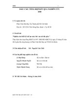
Sự phụ thuộc của hệ số khuếch đại vào tần số
Mạch khuếch đại tạp âm thấp hoạt động tốt, khuếch đại ở dải tần số từ 3.433GHz-3.6GHz. hệ
số khuếch đại 10dB, dải thông 140MHz. Đây là dải tần rộng, phù hợp tuyến thu thông tin vệ
tinh Vinasat băng tần C.
SUMMARY OF THE FINDING OF THE THESIS
Official thesis Title: Reserarch, design, manufacture satellite C-band used in information
transmission Vinasat
Along with the strong development of science and technology, wireless communication
satellite launch and development aimed at improving the disadvantages of terrestrial radio
network, achieve higher capacity, broadband more, it means political, social and economic
big, new service provides convenient and low cost. Currently in Vietnam, aerospace
technology sector are investing in research, this is a new direction, opening up many great
Sơ đồ nguyên lí toàn bộ mạch khuếch đại dùng chip SPF-2086T
benefits for the country. In the satellite communication transceiver very important role, this is
the component affects the quality of satellite signals.
To make satellite C-band we need to design low- noise amplifier with amplificationfactor
of greater than 10dB, the operating frequency from 3.4 to 3.7 GHz
Block diagram of receiver system
Ultrahigh frequency band circuit
We know, in the range of normal radio waves: long, medium and short; theresonant
oscillator circuits were built from the focusing element such as capacitorC and inductor L.
Oscilator circuit to separate the resonant frequency is:
LC2
1
f
0
But in the ultrahigh frequency range, the oscillator circuit (LC) from theconcentration
parameter is no longer working.
First: To obtain the resonant frequencies f0 resonance wavelength large or small, to reduce
the value of L, C to aminimum. But this reduction also has certain limitations due to the
structure of capacitors and inductors. Should in principle not achieve resonance frequency in
the band but as high as cm and mm.
Second: in the ultrahigh frequency band song, the geometric dimensions of the capacitors and
inductors compared with electromagnectic wavelengths, so at this frequency oscillator circuit
itself also acts as a radiation element functionelectromagnetic energy is consumed in the
circuit and the circuit substantiallymaintains no fluctuations in this range.
Third: In the ultrahigh frequency range, when the frequency increases, theconsumption
due to skin effect and dielectric consumed in the inductors and capacitors increaded
significantly, significantly reducing the quality of the LC oscillator circuit, as it takes the
selectivity of the resonant circuit.
So, in the microwave frequency range, we user the oscillator with distributed
parameters, commonly known as cavities.
Coordinate using a wire impedance branch
Coordinate branch wire impedance method is widely used by the simple and easyto
adjust. Can branch into line wiring diagram in parallel or in series with the open circuit or
short circuit writing
Y
L
Y
0
d
A
A
Y
0
Z
L
Z
0
A
A
d
Z
0
Z
0
l
Y
0
l
(a) (b)
Coordinate with the wire impedance branch
Coordinate use two-wire impedance branch
Impedance method using a coordinate branch wire has the advantage of simplicity and can be
used to coordinate all cases characteristic impedance of the load hasreal part 0. But its
drawback is to use a line segment is variable-length stringsplaced between
the load and branch. In some cases we use a coordinated approach using 2-
wire impedance branches are separated by a fixed period.However, this method can not be
used for all cases of load impedance.
Impedance diagram using two coordinate branches is described in Figure 2a, in which
the load can be located by the first branch a wire around any. However, in practice we
often use the diagram Figure 2b, with load wires placed adjacent tothe
first branch. Chart 2b often easier to perform and still not lose the generalityof the
problem. Two wires branching diagram used in Figure 2 is 2 – wire parallelbranches as they
can be made simpler
than the branch wire serial but theoreticallythe completely wired serial branch can
use to coordinate by the impedancemethod. The branch wires can short circuit or open circuit
Map coordinate to use 2-wire impedance branch parallel
EXPERIMENTAL
Research, design and manufacture low-noise amplifier (LNA)
Requirements: Design a low noise amplifier with amplification factor of greater
than 10dB, the operating frequency from 3.4 to 3.7GHz.
Design ideas: To calculate the balance between noise factor and the gain will
require parameters such as, but not necessarily becausethese
parameters were measured according to the desired frequency, on the other hand they You
can choose to use transistorswith low background noise. Components used
are PHEMT GaAsFET SPF-2086T, this is the component amplification coefficientlarge, low-
noise ratio. To achieve maximum magnification factorneed to coordinate the input
impedance and output. In this section,
Iimplement coordinated circuit impedance strip using technology(wireless subsidiary and lam
da / 4)
SPF-2086T High Frequency Chip
Chip SPF-2086T is a high-frequency chips have broad spectrum activity, a
largeamplification factor, in accordance with the design and manufacture of low-
noiseamplifier.
Frequency GHz
Gain dB
3.491
10.333
3.433
7.255
3.575
7.853
3.488
10.387
The dependence of the amplification coefficient on the frequency conclusions
low noise amplifier works well, amplified in a frequency range of 3.6GHz-
3.433GHz. amplification factor of 10dB, a bandwidth of 140MHz. This
isbroadband, online collection of information relevant Vinasat band C.
Summary of the finding of the thesis:
Official thesis Title: Reserarch, design, manufacture satellite C-band used in information
transmission Vinasat
To make satellite C-band we need to design low- noise amplifier with amplificationfactor
of greater than 10dB, the operating frequency from 3.4 to 3.7 GHz
Principle diagram entire amplifier circuit chip used SPF-2086T
Ultrahigh frequency band circuit
We know, in the range of normal radio waves: long, medium and short; theresonant
oscillator circuits were built from the focusing element such as capacitorC and inductor L.
Oscilator circuit to separate the resonant frequency is:
LC2
1
f
0
But in the ultrahigh frequency range, the oscillator circuit (LC) from theconcentration
parameter is no longer working.
First: To obtain the resonant frequencies f0 resonance wavelength large or small, to reduce
the value of L, C to aminimum. But this reduction also has certain limitations due to the
structure of capacitors and inductors. Should in principle not achieve resonance frequency in
the band but as high as cm and mm.
Second: in the ultrahigh frequency band song, the geometric dimensions of the capacitors and
inductors compared with electromagnectic wavelengths, so at this frequency oscillator circuit
itself also acts as a radiation element functionelectromagnetic energy is consumed in the
circuit and the circuit substantiallymaintains no fluctuations in this range.
Third: In the ultrahigh frequency range, when the frequency increases, theconsumption
due to skin effect and dielectric consumed in the inductors and capacitors increaded
significantly, significantly reducing the quality of the LC oscillator circuit, as it takes the
selectivity of the resonant circuit.
So, in the microwave frequency range, we user the oscillator with distributed
parameters, commonly known as cavities.
Coordinate using a wire impedance branch
Coordinate branch wire impedance method is widely used by the simple and easyto
adjust. Can branch into line wiring diagram in parallel or in series with the open circuit or
short circuit writing
Y
L
Y
0
d
A
A
Y
0
Z
L
Z
0
A
A
d
Z
0
Z
0
l
Y
0
l
(a) (b)
Coordinate with the wire impedance branch
Coordinate use two-wire impedance branch
Impedance method using a coordinate branch wire has the advantage of simplicity and can be
used to coordinate all cases characteristic impedance of the load hasreal part 0. But its
drawback is to use a line segment is variable-length stringsplaced between
the load and branch. In some cases we use a coordinated approach using 2-
wire impedance branches are separated by a fixed period.However, this method can not be
used for all cases of load impedance.
Impedance diagram using two coordinate branches is described in Figure 2a, in which
the load can be located by the first branch a wire around any. However, in practice we
often use the diagram Figure 2b, with load wires placed adjacent tothe
first branch. Chart 2b often easier to perform and still not lose the generalityof the
problem. Two wires branching diagram used in Figure 2 is 2 – wire parallelbranches as they
can be made simpler
than the branch wire serial but theoreticallythe completely wired serial branch can
use to coordinate by the impedancemethod. The branch wires can short circuit or open circuit
Map coordinate to use 2-wire impedance branch parallel
EXPERIMENTAL
Research, design and manufacture low-noise amplifier (LNA)
Requirements: Design a low noise amplifier with amplification factor of greater
than 10dB, the operating frequency from 3.4 to 3.7GHz.
SPF-2086T High Frequency Chip
Chip SPF-2086T is a high-frequency chips have broad spectrum activity, a
largeamplification factor, in accordance with the design and manufacture of low-
noiseamplifier.
Frequency GHz
Gain dB
3.491
10.333
3.433
7.255
3.575
7.853
3.488
10.387
The dependence of the amplification coefficient on the frequency conclusions
low noise amplifier works well, amplified in a frequency range of 3.6GHz-
3.433GHz. amplification factor of 10dB, a bandwidth of 140MHz. This
isbroadband, online collection of information relevant Vinasat band C.
Principle diagram entire amplifier circuit chip used SPF-2086T
References
Tiếng Việt
[1]. Cao Quang Hoàng. “Nghiên cứu thiết kế chế tạo máy phát và tuyến thu cao tần dải rộng
băng UHF phục vụ truyền dẫn thông tin” khóa luận tốt nghiệp đại học năm 2010, trường Đại
học Công nghệ, ĐHQGHN
[2]. Nguyễn Phạm Anh Dũng (2007), Thông tin vệ tinh, Trung tâm đào tạo bưu chính viễn
thông 1, mã số 411TVT360, Hà Nội.
[3]. GS.TSKH Phan Anh, Ths Trần Thị Thúy Quỳnh. Giáo trình lý thuyết và kỹ thuật siêu
cao tần, Bộ môn thông tin vô tuyến, Khoa Điện tử - Viễn thông, Trường Đại Học Công
Nghệ - Quốc Gia Hà Nội.
[4]. Phạm Minh Việt. Kỹ thuật siêu cao tần, NXB Khoa học kỹ thuật, Hà Nội.
[5]. PGS.TS Trần Quang Vinh – Ths. Chử Văn An, Nguyên lý kỹ thuật điện tử, NXB Giáo
dục, Hà Nội
Tiếng Anh
[6]. David M.Pozar, Microwave engineering, John Wiley & Sons, Inc.
[7]. Guillermo Gonzalez, Microwave transistor amplifiers, Prentice Hall.