Tài liệu FLUID-STRUCTURE INTERACTIONSSLENDER STRUCTURES AND AXIAL FLOW VOLUME 1 ppt
Bạn đang xem bản rút gọn của tài liệu. Xem và tải ngay bản đầy đủ của tài liệu tại đây (16.45 MB, 598 trang )
I
FLUID-STRUCTURE INTERACTIONS
SLENDER
STRUCTURES
AND AXIAL FLOW
VOLUME
1
FLUID-STRUCTURE INTERACTIONS
SLENDER STRUCTURES AND AXIAL FLOW
VOLUME
1
MICHAEL
P.
PAIDOUSSIS
Department
of
Mechanical Engineering,
McGill University,
Montreal, Que'bec, Canada
W
ACADEMIC PRESS
SAN DIEGO LONDON NEW YORK BOSTON
SYDNEY TOKYO TORONTO
This book is printed
on
acid-free paper.
Copyright
0
1998 by ACADEMIC
PRESS
All
Rights
Reserved.
No
part of this publication may be reproduced
or
transmitted in any form
or
by any means,
electronic
or
mechanical, including photocopy, recording,
or
any information storage and retrieval
system, without permission in writing from the publisher.
Academic Press
525 B Street, Suite 1900, San Diego, California 92101-4495, USA
http:llwww.apnet.com
Academic Press Limited
24-28 Oval Road, London NW
1
7DX,
UK
http:llwww.hbuk.co.uWap/
ISBN 0-12-544360-9
A catalogue record for this book is available from the British Library
Library
of
Congress Catalog Card Number: 98-86469
Typeset by Laser Words, Madras, India
Printed in Great Britain by WBC Book Manufacturers, Bridgend, Mid-Glamorgan
98
99 00 01 02 03 WB 9
8
7
6
5
4
3 2
1
Preface
Artwork Acknowledgnierits
1
Introduction
1.1 General overview
1.2 Classification of flow-induced vibrations
1.3 Scope and contents of volume 1
1.4 Contents of volume 2
2
Concepts. Definitions and Methods
2.1
Discrete and distributed parameter systems
2.1.1 The equations of motion
2.1.2 Brief review of discrete systems
2.1.3 The Galerkin method via a simple example
2.1.4 Galerkin’s method for a nonconservative system
2.1.5 Self-adjoint and positive definite continuous systems
2.1.6 Diagonalization, and forced vibrations of continuous
systems
2.2 The fluid mechanics of fluid-structure interactions
2.2.1 General character and equations of fluid flow
2.2.2 Loading on coaxial shells filled with quiescent fluid
2.2.3 Loading
on
coaxial shells filled with quiescent
viscous fluid
2.3 Linear and nonlinear dynamics
3
Pipes Conveying Fluid: Linear Dynamics
I
3.1 Introduction
3.2 The fundamentals
3.2.1 Pipes with supported ends
3.2.2 Cantilevered pipes
3.2.3 On the various bifurcations
3.3 The equations
of
motion
3.3.1 Preamble
3.3.2 Newtonian derivation
3.3.3 Hamiltonian derivation
3.3.4
A
comment on frictional forces
3.3.5 Nondimensional equation of motion
3.3.6 Methods of solution
xi
xiv
6
6
8
9
12
16
17
18
23
23
36
46
51
59
59
60
60
63
67
69
69
71
76
82
83
84
V
vi
CONTENTS
3.4
Pipes with supported ends
3.4.1
Main theoretical results
3.4.2
Pressurization, tensioning and gravity effects
3.4.3
Pipes on an elastic foundation
3.4.4
Experiments
3.5
Cantilevered pipes
3.5.1
Main thcoretical rcsults
3.5.2
The effect of gravity
3.5.3
The effect of dissipation
3.5.4
The S-shaped discontinuities
3.5.5
On destabilization by damping
3.5.6
Experiments
3.5.7
The effect of an elastic foundation
3.5.8
Effects of tension and refined fluid mechanics modelling
Systems with added springs, supports, masses and other
modifications
3.6.1
Pipes supported at
6
=
1/L
<
1
3.6.2
Cantilevered pipes with additional spring supports
3.6.3
Pipes with additional point masses
3.6.4
Pipes with additional dashpots
3.6.7
Concluding remarks
3.6
3.6.5
Fluid follower forces
3.6.6
Pipes with attached plates
3.7
Long pipes and wave propagation
3.7.1
Wave propagation
3.7.2
Infinitely long pipe on elastic foundation
3.8
Articulated pipes
3.8.1
The basic dynamics
3.8.2
N-Degree-of-freedom pipes
3.8.3
Modified systems
3.8.4
Spatial systems
3.7.3
Periodically supported pipes
4
Pipes Conveying Fluid: Linear Dynamics
I1
4.1
Introduction
4.2
Nonuniform pipes
4.2.1
The equation of motion
4.2.2
Analysis and results
4.2.3
Experiments
4.2.4
Other work on submerged pipes
4.3
Aspirating pipes and ocean mining
4.3.1
Background
4.3.2
Analysis
of
the ocean mining system
4.3.3
Recent developments
4.4
Short pipes and refined flow modelling
4.4.1
Equations of motion
4.4.2
Method of analysis
88
88
98
102
103
111
111
115
118
123
130
133
149
150
153
153
157
164
167
168
170
172
173
173
174
178
183
184
186
190
194
196
196
196
196
203
208
211
213
213
214
217
220
221
224
CONTENTS
vii
4.4.3
The inviscid fluid-dynamic force
4.4.4
The fluid-dynamic force by the integral Fourier-transform
method
4.4.5
Refined and plug-flow fluid-dynamic forces and specification
of the outflow model
4.4.6
Stability of clamped-clamped pipes
4.4.7
Stability of cantilevered pipes
4.4.8
Comparison with experiment
4.4.10
Long pipes and refined flow theory
4.4.11
Pipes conveying compressible fluid
4.5
Pipes with harmonically perturbed flow
4.5.1
Simple parametric resonances
4.5.2
Combination resonances
4.5.3
Experiments
4.5.4
Parametric resonances by analytical methods
4.5.5
Articulated and modified systems
4.5.6
Two-phase and stochastically perturbed flows
4.6
Forced vibration
4.6.1
The dynamics of forced vibration
4.6.2
Analytical methods for forced vibration
4.7
Applications
4.7.1
The Coriolis mass-flow meter
4.7.2
Hydroelastic ichthyoid propulsion
4.7.3
Vibration attenuation
4.7.4
Stability of deep-water risers
4.7.5
High-precision piping vibration codes
4.7.7
Miscellaneous applications
4.8
Concluding remarks
5.1
Introductory comments
5.2
The nonlinear equations of motion
Hamilton's principle and energy expressions
5.2.3
The equation of motion of a cantilevered pipe
5.2.5
Boundary conditions
5.2.6
Dissipative terms
5.2.7
Dimensionless equations
5.2.8
Comparison with other equations for cantilevers
5.2.10
Concluding remarks
5.3
Equations for articulated systems
5.4
Methods of solution and analysis
4.4.9
Concluding remarks on short pipes and refined-flow
models
4.7.6
Vibration conveyance and vibration-induced flow
5
Pipes Conveying Fluid: Nonlinear and Chaotic Dynamics
5.2.1
Preliminaries
5.2.2
5.2.4
The equation of motion for a pipe fixed at both ends
5.2.9
Comparison with other equations
for
pipes with fixed ends
225
228
229
232
236
238
240
241
241
242
243
250
253
258
258
261
261
261
265
267
268
269
270
271
273
274
275
276
277
277
278
279
281
283
285
287
287
288
290
294
295
296
299
CONTENTS
VI11
5.5
Pipes with supported ends
5.5.1 The effect of amplitude on frequency
5.5.2
The post-divergence dynamics
Pipes with an axially sliding downstream end
5.5.4
Impulsively excited 3-D motions
5.6
Articulated cantilevered pipes
5.6.1
Cantilever with constrained end
5.6.2
Unconstrained cantilevers
5.6.3
Concluding comment
5.7
Cantilevered pipes
5.7.1
2-D
limit-cycle motions
5.7.2 3-D
limit-cycle motions
5.7.3
Dynamics under double degeneracy conditions
5.7.4
Concluding comment
5.8
Chaotic dynamics
5.8.1
Loosely constrained pipes
5.8.2
Magnetically buckled pipes
5.8.3
Pipe with added mass at the free end
5.8.4
Chaos near double degeneracies
5.8.5
Chaos in the articulated system
5.9
Nonlinear parametric resonances
Pipes with supported ends
5.9.2
Cantilevered pipes
5.10
Oscillation-induced flow
5.11
Concluding remarks
5.5.3
5.9.1
6
Curved Pipes Conveying Fluid
6.1
Introduction
6.2
Formulation of the problem
6.2.1
Kinematics
of
the system
6.2.2
The equations of motion
6.2.3
The boundary conditions
6.2.4
Nondimensional equations
6.2.5
Equations of motion of an inextensible pipe
6.2.6
Equations of motion of an extensible pipe
6.3
Finite element analysis
Analysis for inextensible pipes
6.4
Curved pipes with supported ends
6.4.1
Conventional inextensible theory
6.4.2
Extensible theory
6.4.3
Modified inextensible theory
6.4.4
More intricate pipe shapes and other work
6.4.5
Concluding remarks
6.5.1
Modified inextensible and extensible theories
6.5.2
Nonlinear and chaotic dynamics
6.3.1
6.3.2
Analysis for extensible pipes
6.5
Curved cantilevered pipes
302
302
303
314
315
316
316
317
327
328
328
333
336
348
348
348
366
368
387
392
394
394
402
412
413
415
415
417
417
421
426
426
428
429
430
431
436
437
438
440
446
448
451
452
452
457
CONTENTS
ix
6.6
Curved pipes with an axially sliding end
6.6.1
Transversely sliding downstream end
6.6.2
Axially sliding downstream end
Appendices
A First-principles Derivation
of
the Equation
of
Motion
of
a Pipe
Conveying Fluid
B Analytical Evaluation
of
b
and
d
C
Destabilization by Damping:
T
.
Brooke Benjamin’s Work
D Experimental Methods
for
Elastomer Pipes
D.l
D.2
Materials. equipment and procedures
Short pipes. shells and cylinders
D.3
Flexural rigidity and damping constants
D.4
Measurement
of
frequencies and damping
E.l
The equations of motion
The eigenfunctions of a Timoshenko beam
E.3
The integrals
Zkn
F.l
Lyapunov method
F.l
.
1
The concept of Lyapunov stability
F
.
1.2
Linearization
F
.
1.3 Lyapunov direct method
F.2
Centre manifold reduction
F.3
Normal forms
F.4
The method
of
averaging
F.5
Bifurcation theory and unfolding parameters
F.6
Partial differential equations
F.6.1
The method of averaging revisited
F.6.2
The Lyapunov-Schmidt reduction
The method of alternate problems
E The Timoshenko Equations
of
Motion and Associated Analysis
E.2
F Some
of
the Basic Methods
of
Nonlinear Dynamics
F.6.3
G
Newtonian Derivation
of
the Nonlinear Equations
of
Motion
of
a Pipe
Conveying Fluid
G.l
Cantilevered pipe
G.2
Pipe fixed at both ends
H
Nonlinear Dynamics Theory Applied to
a
Pipe Conveying Fluid
H.l
Centre manifold
H.2
Normal form
H.2.2
Static instability
H.2.1
Dynamic instability
459
460
460
463
466
468
471
471
473
474
476
478
478
480
481
483
483
483
484
486
487
489
491
493
495
495
498
500
502
502
503
506
506
507
507
515
X
CONTENTS
I
The Fractal Dimension from the Experimental Pipe-vibration Signal
516
J
Detailed Analysis for the Derivation of the Equations of Motion
of
Relationship between
(XO,
yo,
ZO)
and
(x,
y,
z)
.
. . . . .
.
. . . . . . .
.
. . .
The expressions for curvature and twist . . . .
.
. .
.
.
. .
. . .
.
. .
.
.
.
. .
Derivation
of
the fluid-acceleration vector
. .
.
.
. .
.
.
.
. .
.
.
. .
.
. . .
.
The equations of motion for the pipe
.
.
. . .
.
. .
.
. .
.
. .
.
.
.
.
.
.
. .
.
Chapter 6
522
J.l
522
J.2
523
5.3
523
5.4
524
K
Matrices
for
the Analysis of an Extensible Curved Pipe
Conveying Fluid
529
References
.
. . . . . . . .
.
.
.
.
. . . . . . . .
.
.
. .
.
. . . . .
.
.
.
, ,
.
.
. .
.
. . .
.
.
53
1
Index
558
Preface
A word about
la raison d’2tre
of this book could be useful, especially since the first
question to arise
in
the prospective reader’s mind might be:
why another
book
on
pow-
induced vibration?
Flow-induced vibrations have been with us since time immemorial, certainly
in
nature,
but also
in
artefacts; an example of the latter is the Aeolian harp, which also makes
the point that these vibrations are not always a nuisance. However,
in
most instances
they
are
annoying
or
damaging to equipment and personnel and hence dangerous, e.g.
leading to
the
collapse of tall chimneys and bridges, the destruction of heat-exchanger and
nuclear-reactor intemals, pulmonary insufficiency, or the severing of offshore risers. In
virtually all such cases, the problem is ‘solved’, and the repaired system remains trouble-
free thereafter
-
albeit, sometimes, only after a first and even a second iteration
of
the
redesigned and supposedly ‘cured’ system failed also. This gives a hint of the reasons why
a book emphasizing (i)
thefundamentals
and (ii)
the mechanisnis givitig rise
to
thepow-
induced vibration
might be useful to researchers, designers, operators and,
in
the broadest
sense of the word, students of systems involving fluid-structure interactions.
For,
in
many
cases, the aforementioned problems were ‘solved’ without truly understanding either the
cause of the original problem or the reasons why the cure worked,
or
both. Some of the
time-worn battery of ‘cures’, e.g. making the structure stiffer via stiffeners or additional
supports, usually work, but often essentially ‘sweep the problem under thc carpet’, for
it
to re-emerge under different operating conditions
or
in
a different part of the parameter
space; moreover, as we shall see
in
this book, for a limited class of systems, such measures
may actually be counterproductive.
Another answer to the original question ‘Why yet another book?’ lies
in
the choice
of the material and the style of its presentation. Although the discussion and citation of
work
in
the area is as complete as practicable, the style is not encyclopaedic;
it
is sparse,
aiming to convey the main ideas in a physical and comprehensible manner, and
in
a way
that
isfun
to
read.
Thus, the objectives of the book are (i) to convey an understanding
of the undoubtedly fascinating (even for the layman) phenomena discussed,
(ii)
to give a
complete bibliography of all important work
in
the field, and
(iii)
to provide some tools
which the reader can use to solve other similar problems.
A
second possible question worth discussing is ‘Why the relatively narrow focus?’
By glancing through the contents,
it
is immediately obvious that the book deals with
axial-flow-related problems, while vortex-induced motions
of
bluff bodies, fluidelastic
instability of cylinder arrays
in
cross-flow, ovalling oscillations of chimneys, indeed all
cross-flow-related topics, are excluded. Reasons for this are that
(i)
some of these topics
are already well covered in other books and review articles;
(ii)
in
at least some cases, the
fundamentals are still under development, the mechanisms involved being incompletely
understood; (iii) the cross-flow literature is
so vast, that any attempt to cover
it,
as well as
axial-flow problems, would by necessity squeeze the latter into one chapter
or
two, at most.
xi
xii
PREFACE
After extensive consultations with colleagues around the world,
it
became clear that there
was a great need for
a
monograph dealing exclusively with axial-flow-induced vibrations
and instabilities. This specialization translates also into a more cohesive treatment
of
the
material to be covered. The combination of axial flow and slender structures implies,
in
many cases, the absence
or,
at most, limited presence of separated flows. This renders
analytical modelling and interpretation of experimental observation far easier than
in
systems involving bluff bodies and cross-flow; it permits a better understanding of the
physics and makes a more elegant presentation of the material possible. Furthermore,
because the understanding of the basics
in
this area is now well-founded, this book
should remain useful for some time to come.
In a real sense, this book
is
an anthology
of
much of the author’s research endeavours
over the past
35
years, at the University
of
Cambridge, Atomic Energy of Canada in
Chalk River and, mainly, McGill University
-
with a brief but important interlude at
Cornell University. Inevitably and appropriately, however, vastly more than the author’s
own work is drawn upon.
The book has been written for engineers and applied mechanicians;
the
physical systems
discussed and the manner in which they are treated may also be of interest to applied
mathematicians.
It
should appeal especially to researchers, but it has been written for
practising professionals (e.g. designers and operators) and researchers alike. The material
presented should be easily comprehensible to those with some graduate-level under-
standing of dynamics and fluid mechanics. Nevertheless, a real attempt has been made to
meet the needs of those with a Bachelor’s-level background. In this regard, mathematics
is treated as a useful tool, but not as an end
in
itself.
This book is not an undergraduate text, although
it
could be one for a graduate-level
course. However,
it
is
not written in rext-book format, but rather in a style to be enjoyed
by a wider readership.
I should like
to
express my gratitude to
my
colleagues, Professor. B.G. Newman for
his help with Section
2.2.1,
Professors S.J. Price and A.K. Misra for their input mainly
on Chapters
3
and 6, respectively,
Dr
H. Alighanbari for input on several chapters and
Appendix
F,
and Professor D.R. Axelrad for his help
in
translating difficult papers in
Gernian.
I am especially grateful and deeply indebted to
Dr
Christian Semler for some special
calculations, many suggestions and long discussions, for checking and rechecking every
part of the book, and particularly for his contributions to Chapter
5
and for Appendix
F,
of which he is the main creator. Also, many thanks go to Bill Mark
for
his willing help
with some superb computer graphics and for input on Appendix D, and to David Sumner
for help with an experiment for Section
4.3.
I am also grateful to many colleagues outside McGill for their help: Drs D.J. Maul1 and
A. Dowling of Cambridge, J.M.T. Thompson of University College London,
S.S.
Chen
of
Argonne,
E.H.
Dowel1 of Duke, C.D. Mote Jr of Berkeley, F.C. Moon of Cornell,
J.P.
Cusumano of Penn State, A.K. Bajaj of Purdue, N.S. Namachchivaya
of
the
Univer-
sity of Illinois,
S.
Hayama and
S.
Kaneko of the University of Tokyo,
Y.
Sugiyama of
Osaka Prefecture, M. Yoshizawa of Keio, the late
Y.
Nakamura of Kyushu and many
others, too numerous to name.
My gratitude
to
my secretary, Mary Fiorilli,
is
unbounded, for without her virtuosity
and dedication this book would not have materialized.
PREFACE
XI11
Finally, the loving support and constant encouragement by my wife Vrissei’s
(Bpiaqi’s)
has been a
sine
qua
non
for the completion of this book, as my mother’s exhortations
to
‘be laconic’ has been useful. For what
little
versatility
in
the use of English this volume
may display,
I
owe a great deal to my late first wife, Daisy.
Acknowledgements are also due
to
the Natural Sciences and Engineering Research
Council of Canada, FCAR of QuCbec and McGill University for their support, the Depart-
ment
of
Mechanical Engineering for their forbearance, and
to
Academic Press
for
their
help and encouragement.
Michael
P.
Paldoussis
McGill Universify,
Montreal, Que‘bec,
Canada.
Artwork
Acknowledgements
A number of figures used in this book have been reproduced from papers
or
books, often
with the writing re-typeset, by kind permission of the publisher and the authors. In most
cases permission was granted without any requirement for a special statement; the source
is nevertheless always cited.
In some cases, however, the publishers required special statements, as follows.
Figure 3.4 from Done &-Simpson (1977),+ Figure 3.10 from Pafdoussis (1975),
Figures 3.24 and 3.25 from Naguleswaran
&
Williams (1968), Figures 3.32, 3.33
and 3.49-3.51 from Paidoussis (1970), and Figures 3.78-3.80 from PaYdoussis
&
Deksnis (1970) are reproduced by permission of the Council of the Institution of
Mechanical Engineers,
U.K.
Figures 3.3 and 5.1 l(b) from Thompson (1982b) by permission of Macmillan Maga-
zines Ltd.
Figures 3.55,
3.58
and 3.60 from Chen
&
Jendrzejczyk (1985) by permission of the
Acoustical Society of America.
Figures 3.54 and 3.59 from Jendrzejczyk
&
Chen (1985), Figure 3.71 from Hemnann
&
Nemat-Nasser (1967), Figure 5.29 from Li
&
Pafdoussis (1994), Figures 5.43 and
5.45-5.48 from Pdidoussis
&
Semler (1998), and Figure
5.60
from Namachchivaya
(1989) and Namachchivaya
&
Tien (1989a) by permission of Elsevier Science Ltd.,
The Boulevard, Langford Lane, Kidlington,
OX5
IGB, U.K.
Figure
5.16
from Sethna
&
Shaw (1987) and Figures 5.57(a,b) and 5.58 from
Champneys (1 993) by permission of Elsevier Science-NL, Sara Burgerhartstraat
25,
1055
KV Amsterdam, The Netherlands.
Figure 4.38(a) from Lighthill (1969) by permission of Annual Review of Fluid
Mechanics.
~~
See bibliography
for
the complete reference.
xiv
1
Introduction
1.1
GENERAL OVERVIEW
This book deals with the dynamics of slender, mainly cylindrical
or
quasi-cylindrical,
bodies in contact with axial flow
-
such that the structure either contains the flow
or
is immersed in it,
or
both.
Dyrzamics
is used here
in
its genetic sense, including
aspects of
srabiliry,
thus covering both self-excited and free
or
forced motions
associated with fluid-structure interactions in such configurations. Indeed, flow-induced
instabilities
-
instabilities in the linear sense, namely, divergence and flutter
-
are a
major concern of this book. However, what is rather unusual for books on flow-induced
vibration, is that considerable attention is devoted to the
nonlinear
behaviocrr
of
such
systems, e.g. on the existence and stability of limit-cycle motions, and the possible
existence of
chaotic
oscillations.
This necessitates the introduction and utilization of some
of the tools of modem dynamics theory.
Engineering examples of slender systems interacting with axial flow are pipes and other
flexible conduits containing flowing fluid, heat-exchanger tubes in axial flow regions of
the secondary fluid and containing internal flow of the primary fluid, nuclear reactor
fuel elements, monitoring and control tubes, thin-shell structures used as heat shields
in
aircraft engines and thermal shields in nuclear reactors, jet pumps, certain types of valves
and other components
in
hydraulic machinery, towed slender ships, barges and submarine
systems, etc. Physiological examples may be found
in
the pulmonary and urinary systems
and
in
haemodynamics.
However, much of the work in this area has been, and still is, ‘curiosity-driven’,’
rather than applications-oriented. Indeed, although some of the early work on stability of
pipes conveying fluid was inspired by application to pipeline vibrations,
it
soon became
obvious that the practical applicability of this work to engineering systems was rather
limited. Still, the inherent interest of the extremely varied dynamical behaviour which
this system is capable of displaying has propelled researchers to do more and more
work
-
to the point where in a recent review (PaYdoussis
&
Li
1993)
over
200
papers
were cited in a not-too-exhaustive bibliography.$ In the process, this topic has become
a new paradigm
in
dynamics, i.e. a new
model dynamical problem,
thus serving two
purposes:
(i)
to illustrate known dynamical behaviour
in
a simple and convincing manner;
‘With the present emphasis on utilitarianism in engineering and even science research, the characterization
of
a
piece of work
as
‘curiosity-driven’ stigmatizes
it
and, in the minds of some, brands
it
as being ‘useless’.
Yet, some of the highest achievements of the human mind in science (including medical and engineering
science) have indeed been curiosity-driven; most have ultimately found some direct
or
indirect, and often very
important, practical application.
*See also Becker (1981) and Paidoussis (1986a.
1991).
1
2
SLENDER STRUCTURES AND AXIAL
FLOW
(ii) to serve as a vehicle in the search for new phenomena
or
new dynamical features,
and in the development of new mathematical techniques. More of this will be discussed
in Chapters 3-5. However, the foregoing serves to make the point that the curiosity-
driven work on the dynamics of pipes conveying fluid has yielded rich rewards, among
them (i) the development of theory for certain classes of dynamical systems, and of new
analytical methods for such systems, (ii) the understanding of the dynamics of more
complex systems (covered in Chapters 6-11 of this book), and (iii) the direct use of
this work
in
some
a
priori
unforeseen practical applications, some 10 or
20
years after
the original work was done (Paidoussis 1993). These points also justify why
so
much
attention, and space, is devoted
in
the book to this topic, indeed Chapters 3-6.
Other topics covered in the book (e.g. shells containing flow, cylindrical structures
in axial or annular flow) have more direct application to engineering and physiological
systems; one will therefore find sections in Chapters
7-
11 entirely devoted to applications.
In fact, since ‘applications’ and ‘problems’ are often synonymous, it may be of interest to
note that, in a survey of flow-induced vibration problems
in
heat exchangers and nuclear
reactors (Paidoussis 1980), out of the
52
cases tracked down and analysed, 36% were
associated with axial flow situations. Some of them, notably when related to annular
configurations, were very serious indeed
-
in one case the repairs taking three years, at
a total cost, including ‘replacement power’ costs,
in
the hundreds of millions of dollars,
as described in Chapter 11.
The stress in this book is on the fundamentals as opposed to techniques and on physical
understanding whenever possible. Thus, the treatment
of
each sub-topic proceeds from
the very simple, ‘stripped down’ version of
the
system, to the more complex or realistic
systems. The analysis of the latter invariably benefits from a sound understanding of the
behaviour of the simpler system. There are probably two broad classes of readers of
a
book such as this: those who are interested
in
the
subject matter
per
se,
and those who
skim through it in the hope of finding here the solution to some specific engineering
problem.
For
the benefit of the latter, but also to enliven the book for the former group,
a few ‘practical experiences’ have been added.
It must be stressed, however, for those with limited practical experience of flow-induced
vibrations, that these problems can be very difficult. Some of the reasons for this are:
(i) the system as a whole may be very complex, involving a multitude of components,
any one of which could be the real culprit; (ii) the source of the problem may be far
away from the point of its manifestation; (iii) the information available from the field,
where the problem has arisen, may not contain what the engineers would really hope to
know in order to determine its cause. These three aspects of practical difficulties will be
illustrated briefly by three examples.
The first case involved a certain type of boiling-water nuclear reactor
(BWR)
in
which
the so-called ‘poison curtains’, a type of neutron-absorbing device, vibrated excessively,
impacting on the fuel channels and causing damage (Paidoussis 1980; Case
40).
It was
decided
to
remove them. However, this did not solve the problem, because
it
was then
found that
the
in-core instrument tubes, used to monitor reactivity and located behind
thc curtains, vibrated sufficiently to impact on the fuel channels
-
‘a
problem that was
“hidden behind the curtains” for the first two years’
!
Although this may sound amusing
at this point, neither the power-station operator nor the team of engineers engaged
in
the
solution of
the
problem can have found
it
so
at the time.
INTRODUCTION
3
The second case also occurred in a nuclear power station, this time a gas-cooled system
(PaYdoussis 1980; Case
35).
It involved excessive vibration of the piping
-
so excessive
that the sound associated with this vibration could be heard 3km away! The excitation
source was not local; it was a vortex-induced vibration within the steam generator, quite
some distance away.
A
similar but less spectacular such case involved
the
perplexing
vibration of control piping in the basement of the Macdonald Engineering Building at
McGill University, which occurred intermittently. The source was eventually, and quite
by chance, discovered to be a small experiment involving a plunger pump
(to
study
parametric oscillations of piping, Chapter
4)
three floors up!
Another case involved a boiler (Pdidoussis 1980; Case 23), and the report from the
field stated that ‘There is severe vibration on this unit. The forced draft duct, gas duct
and superheater-economizer sections all vibrate. The frequency I would guess to be
60-100
cps. It feels about like one of those ‘ease tired feet’ vibration machines’.
A
very colourful description, but lacking
in
the kind of detail and quantitative information
one would wish for. The difficulty
of
instrumenting the troublesome operating system
a
posteriori
should also be remarked upon.
To be able to deal with practical problems involving flow-induced vibration
or
insta-
bility, one needs first of all a certain breadth
of
perspective to be able to recognize
in
what class of phenomena
it
belongs,
or
at least
in
what class it definitely does
not
belong.
Here experience is a great asset; reference to books with a broader scope would also
be recommended [e.g. Naudascher
&
Rockwell (1994), Blevins (1990)l. Once the field
has been narrowed, however, to be able to solve and to redesign properly the system, a
thorough familiarity with the topic is indispensable. If the problem is one of axial flow,
then here is where this book becomes useful.
A
final point, before embarking on more specific items, should also be made: despite
what was said at the beginning of the discussion on practical concerns
-
that applica-
tions and problems are often synonymous
-
flow-induced vibrations are not necessarily
bad.
First
of
all, they are omnipresent; a fact
of
life, one might say. They occur when-
ever
a
structure is
in
contact with flowing fluid, no matter how small the flow velocity.
Admittedly, in many cases the amplitudes of vibration are very small and hence the
vibration may be quite inconsequential. Secondly, even
if
the vibration is substantial,
it
may have desirable features, e.g.
in
promoting mixing, dispersing of plant seeds, making
music by reed-type wind instruments; as well as for wave-generated energy conversion,
or
for the enhancement of marine propulsion (Chapter
4).
Recently, attempts have been
made ‘to harness’ vibration in heat-exchange equipment
so
as to augment heat transfer,
so
far without spectacular success, however. Even chaotic oscillation, usually a term with
negative connotations, can be useful, e.g. in enhancing mixing (Aref 1995).
1.2
CLASSIFICATION OF FLOW-INDUCED VIBRATIONS
A
number
of
ways
of
classifying flow-induced vibrations have been proposed.
A
very
systematic and logical classification is due to Naudascher
&
Rockwell (1980, 1994),
in
terms of the
sources
of
excitation
of flow-induced vibration, namely,
(i)
extraneously
induced excitation, (ii) instability-induced excitation, and (iii) movement-induced excita-
tion. Naudascher
&
Rockwell consider flow-induced excitation of both body and fluid
oscillators, which leads to a
3
x
2 tabular matrix within which any given situation can
be accommodated;
in
this book, however, we are mainly concerned with flow-induced
4
SLENDER STRUCTURES AND
AXIAL FLOW
structural
motions, and hence only half of this matrix is of direct interest. The struc-
ture,
or
‘body oscillator’, is any component with a certain inertia, either elastically
supported
or
flexible (e.g. a flexibly supported rigid mass, a beam,
or
a shell).
Thus,
in a one-degree-of-freedom system, the equation of which may generally be written as
i
+
mix
+
g(x,
i,
x)
=
f(t),
the
first two terms must be present, i.e. the structure,
if
appropriately excited, must be able to oscillate!
Extraneously induced excitation
(EIE) is defined as being caused by fluctuations in
the flow
or
pressure, independently of any flow instability and any structural motion.
An
example is the turbulence buffeting,
or
turbulence-induced excitation, of a cylinder
in
flow,
due to surface-pressure fluctuations associated with turbulence
in
the flow.
Instability-
induced
excitation
(IIE)
is associated with a flow instability and involves local flow
oscillations. An example is the alternate vortex shedding from a cylindrical structure.
In this case it is important to consider the possible existence of a control mechanism
governing and perhaps enhancing the strength
of
the excitation: e.g. a fluid-resonance
or
a fluidelastic feedback. The classical example is that of lock-in, when the vortex-shedding
frequency is captured by the structural frequency near simple, sub-
or superharmonic reso-
nance; the vibration here further organizes and reinforces the vortex shedding process.
Finally, in
movement-induced excitation
(MIE) the fluctuating forces arise from move-
ments of the body; hence, the vibrations are self-excited. Flutter of an aircraft wing and
of a cantilevered pipe conveying fluid are examples of this type of excitation. Clearly,
certain elements of IIE with fluidelastic feedback and MIE are shared; however, what
distinguishes MIE is that in the absence of motion there is no oscillatory excitation
whatsoever.
A similar classification, related more directly to the nature
of
the vibration
in
each
case, was proposed earlier by Weaver (1976): (a) forced vibrations induced by turbulence;
(b) self-controlled vibrations, in which some periodicity exists
in
the flow, independent of
motion, and implying some kind of fluidelastic control via a feedback loop; (c) self-excited
vibrations. Other classifications tend to be more phenomenological. For example, Blevins
(1990) distinguishes between vibrations induced by (a) steady flow and (b) unsteady
flow. The former are then subdivided into ‘instabilities’ (i.e. self-excited vibrations) and
vortex-induced vibrations. The latter are subdivided into: random, e.g. turbulence-related;
sinusoidal, e.g. wave-related; and transient oscillations, e.g. water-hammer problems.
All these classifications, and others besides, have their advantages. Because this book
is essentially a monograph concerned with a subset of the whole field of flow-induced
vibrations, adherence to a single classification scheme is not
so
crucial; nevertheless, the
phenomenological classification will be used more extensively. In this light, an important
aim
of
this section
is
to
sensitize the reader to the various types
of
phenomena
of
interest
and to some of the physical mechanisms causing them.
1.3
SCOPE AND CONTENTS
OF
VOLUME
1
Chapter
2
introduces some of the concepts and methods used throughout the book, both
from the fluids and the structures side
of things. It is more of a refresher than a textbook
treatment
of
the subject matter, and much of it is developed with the aid of examples.
At least some of the material is not too widely known; hence, most readers will find
something of interest. The last part of the chapter introduces some of the differences
in
INTRODUCTION
5
dynamical behaviour as obtained via linear and nonlinear analysis, putting the emphasis
on physical understanding.
Chapters
3
and
4
deal with the dynamics, mainly the stability, of straight (as opposed
to curved) pipes conveying fluid: both
for
the inherently conservative system (both ends
supported) and for the nonconservative one (e.g. when one end of the pipe is free).
The fundamentals of system behaviour are presented in Chapter
3
in
terms of linear
theory, together with the pertinent experimental research. Chapter
4
treats some ‘less
usual’ systems: pipes sucking fluid, nonuniform pipes, parametric resoriances, and
so on,
and also contains a section on applications. The nonlinear dynamics of the system, as
well as chaotic oscillations, are presented in Chapter
5,
wherein may also be found an
introduction to the methods of modern nonlinear dynamics theory.
The ideas and methods developed and illustrated in Chapters
3-5
are of importance
throughout the rest of the book, since the fundamental dynamical behaviour of the systems
in the other chapters will be explained by analogy
or
reference to that presented
in
these
three chapters; hence,
even
if the reader has no special interest in the dynamics of pipes
conveying fluid, reading Chapter
3
is
sine
qua
non
for the proper understanding of the
rest of the book.
Chapter
6
deals with the dynamics of curved pipes conveying fluid, which, surprisingly
perhaps, is distinct from and analytically more complex than that of straight pipes.
1.4
CONTENTS
OF VOLUME
2+
The pipes considered
in
Chapters
3-6
are sufficiently thick-walled to suppose that ideally,
their cross-section remains circular while in motion,
so
that the dynamics may be treated
via beam theory. In Chapter
7,
thin-walled pipes are considered, which must be treated as
thin cylindrical shells. Turbulence-induced vibrations, as well as physiological applications
are discussed at the end of this chapter.
Chapters
8
and
9
deal with the dynamics of cylinders
in
axial flow: isolated cylinders
in unconfined
or
confined flow
in
Chapter
8,
and cylinders
in
clusters
in
Chapter
9.
The
stability and turbulence-induced vibrations of such systems are also discussed. Engineering
applications are also presented: e.g. submerged towed cylinders, and clustered cylinders
such as those used
in
nuclear reactor fuel bundles and tube-in-shell heat exchangers.
Chapter
10
deals with plates in axial flow.
Chapter
11
treats a special, technologically important, case of the material in Chapters
7
and
8:
a single cylinder
or
shell in a rigid
or
flexible tube, subjected to annular flow
in
the
generally narrow passage in-between. This chapter also closes with discussion
of some
engineering applications.
Chapter
12
presents
in
outline some topics involving axial flow not treated
in
detail
in
this book, and Chapter
13
contains some general conclusions and remarks.
‘Volume
2
is
scheduled
to
appear
later, but
soon
after
Volume
1.
2
Concepts, Definitions and
Methods
As
the title implies, this also is an introductory chapter, where some of the basics of the
dynamics of structures, fluids and coupled systems are briefly reviewed with the aid of a
number of examples. The treatment is highly selective and it is meant to be a refresher
rather than a substitute for a more formal and complete development of either solid
or
fluid mechanics,
or
of systems dynamics.
Section
2.1
deals with the basics of discrete and distributed parameter systems, and the
classical modal techniques, as well as the Galerkin method for transforming a distributed
parameter system into a discrete one. Some of the definitions used throughout the book
are given here.
A
great deal
if
not all of this material is well known to most readers;
yet, some unusual features (e.g. those related to nonconservative systems or systems with
frequency-dependent boundary conditions) may interest even the
cognoscenti.
The structure of Section
2.2,
dealing with fluid mechanics, is rather different. Some
generalities on the various flow regimes of interest (e.g. potential flow, turbulent flow)
are given first, both physical and
in
terms of the governing equations. This is
then
followed
by two examples, in which the fluid forces exerted on an oscillating structure are calcu-
lated, for: (a) two-dimensional vibration of coaxial shells coupled by inviscid fluid
in
the annulus; (b) two-dimensional vibration of a cylinder
in
a coaxial tube filled with
viscous
fluid.
Finally,
in
Section
2.3,
a brief discussion is presented on the dynamical behaviour of
fluid-structure-interaction systems,
in
particular the differences when this is obtained via
nonlinear as opposed to linear theory.
2.1
DISCRETE
AND
DISTRIBUTED PARAMETER SYSTEMS
Some systems, for example a mathematical simple pendulum, are
sui getieris
discrete;
i.e. the elements of inertia and the restoring force are not distributed along the geometric
extent of the system. However, what distinguishes a discrete system more precisely is that
its configuration and position in space at any time may be determined from knowledge of
a numerable set of quantities; i.e. the system has a finite number of degrees of freedom.
Thus, the simple pendulum has one degree of freedom, even
if
its mass
is
distributed
along its length, and a double (compound) pendulum has two.
The quantities (variables) required to completely determine the position of the system
in space are the
generalized coordiwates,
which are not unique, need not be inertial, but
must be equal to the number of degrees
of
freedom and mutually independent (Bishop
&
6
CONCEPTS, DEFINITIONS AND METHODS
7
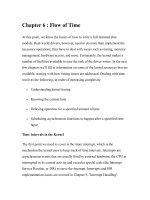
Figure 2.1
(a)
A
mathematical double pendulum involving massless rigid bars
of
length
I,
and
12
and concentrated masses
MI
and
Mz;
(b)
a
three-degree-of-freedom
(N
=
3)
articulated pipe
system conveying
fluid,
with
rigid
rods of mass per
unit
length
m
and length
I,
interconnected
by
rotational springs
of
stiffness
k,
and generalized coordinates
Oi(t),
i
=
1,2,
3;
(c)
a
continuously
flexible cantilevered pipe conveying
fluid,
the
limiting
case of the articulated system
as
N
+
00,
with
EI
=
kl
(see Chapter
3).
In
most of this chapter U
=
0.
Johnson 1960; Meirovitch 1967, 1970). Thus, for a double pendulum [Figure 2.l(a)], the
two angles,
81
and
8,
may be chosen as the generalized coordinates, each measured from
the vertical; or, as the second coordinate, the angle
,y
between the first and the second
pendulum may be used. Closer to the concerns of this book, a vertically hung articulated
system consisting of
N
rigid pipes interconnected by rotational springs (Chapter
3)
has
N
degrees of freedom; the angles,
Oi,
of each of the pipes to the vertical may be utilized as
the generalized coordinates [Figure 2.l(b)]. Contrast this to a flexible pipe [Figure 2.l(c)],
where the mass
arid
flexibility (as well as dissipative forces) are distributed along the
length:
it
is effectively a beam, and this is a
distributedparameter,
or
‘continuous’, system;
in this case, the number of degrees of freedom is infinite. Discrete systems are described
mathematically by ordinary differential equations (ODES), whereas distributed param-
eter systems by partial differential equations (PDEs). If a system is linear,
or
linearized,
which
is
admissible if the motions are small (e.g. small-amplitude vibrations about
the
equilibrium configuration), the ODES may generally be written
in
matrix form. This is
very convenient, since computers understand matrices very well! In fact, a number of
generic matrix equations describe most systems (Pestel
&
Leckie 1963; Bishop
et al.
1965; Barnett
&
Storey 1970; Collar
&
Simpson 1987; Golub
&
Van Loan, 1989) and
they may be solved with the aid of a limited number of computer subroutines [see, e.g.
Press
et al.
(1992)l. Thus, a damped system subjected to a set
of
external forces may be
8
SLENDER
STRUCTURES
AND AXIAL
FLOW
where
[MI,
[C]
and
[K]
are, respectively, the mass, damping and stiffness matrices,
{q)
is the vector of generalized coordinates, and
[Q}
is the vector of the imposed forces; the
overdot denotes differentiation with time.
On the other hand, the form of
PDEs
tends to vary much more widely from one
system
to another. Although helpful classifications (e& into hyperbolic and elliptic types,
Sturm-Liouville-type problems, and
so
on) exist, the fact remains that the equations of
motion of distributed parameter sytems are more varied than those of discrete systems,
and
so
are the methods of solution. Also, the solutions are generally considerably more
difficult,
if
the equations are tractable at all by other than numerical means. Furthermore,
the addition of some new feature to a known problem (i.e. to a problem the solution
of which is known), is not easily accommodated
if
the system is continuous. Consider,
for instance the situation
of
the articulated pipe system which can be described by an
equation such as
(2.1),
and the ease with which the addition of a supplemental mass at
the free end can be accommodated. Then, contrast this to the difficulties associated with
the addition of such a mass to a continuously flexible pipe: since the boundary conditions
will now be different, this problem has to be solved from scratch, even
if
the solution of
the problem without the mass (Le. the solution of the simple beam equation) is already
known. Hence,
it
is often advantageous to transform distributed parameter systems into
discrete ones by such methods as the Galerkin
(or
Ritz-Galerkin)
or
the Rayleigh-Ritz
schemes (Meirovitch
1967).
In this section, tirst the standard methods of analysis
of
discrete systems will be
reviewed. Then, the Galerkin method will be presented via example problems, as well
as methods for dealing with the forced response of continuous systems. Along the way,
a number of important definitions and classifications of systems, e.g. conservative and
nonconservative, self-adjoint, positive definite, etc., will be introduced.
2.1.1
The equations
of
motion
The equations of motion
of
discrete systems are generally derived by either Newtonian
or
Lagrangian methods. In the latter case, for a system of
N
degrees of freedom and
generalized coordinates
qr,
the Lagrange equations
are
d aT aT
av
(G)
-
+
ag,
=Qr,
r
=
1,2,
,
N,
where
T
is the kinetic energy and
V
the potential energy of some
or
all of the conservative
forces acting on the system, while
Qr
are the generalized forces associated with the rest
of the forces (Bishop
&
Johnson 1960; Meirovitch 1967, 1970).
For continuous (distributed parameter) systems, the equations of motion may be
obtained either by Newtonian methods (by taking force and moment balances on an
element of
the
system)
or
by the use of Hamilton's principle and variational techniques,
i.e. by using
(2.3)
S
I"
(T
-
V+
W)dr
=
0,