Tài liệu physical metallurgy 4e volume2 pptx
Bạn đang xem bản rút gọn của tài liệu. Xem và tải ngay bản đầy đủ của tài liệu tại đây (28.34 MB, 944 trang )
h
1
IC
Robert
W.
Cahn
and
Peter
Haasen
(-I),
editors
FOURTH,
REVISED
AND
ENHANCED
EDITION
[NORTH-HOLLAND
PHYSICAL
METALLURGY
VOLUME
I1
LIST
OF
CONTRIBUTORS
A.S.
Argon
E.
Arzt
H.
K.
D.
H.
Bhadeshia
H. Biloni
J.
L
Bocquet
W.
J.
Boettinger
G. Brebec
R.W. Cahn
G.Y.
Chin?
T.
W.
Clyne
R.D.
Doherty
H.E. Exner
R. Ferro
D.R. Gaskell
H. Gleiter
A.L. Greer
P.
Haasen?
J.
P.
Hirth
S.
Hofmann
E.D.
Hondros
E.
Hornbogen
G.
Kostorz
C. Laird
I?
LejEek
W.C. Leslie
Y.
Limoge
J.
D.
Livingston
E
E. Luborsky
T.B. Massalski
J.
R.
Nicholls
AD. Pelton
D.G. Pettifor
D.P. Pope
M. Riihle
A.
Saccone
S.
R.
J.
Saunders
M.P. Seah
W. Steurer
J L. Strudel
R.M. Thomson
C.M. Wayman
M. Wilkens
A.
H. Windle
H.
J.
Wollenberger
PHYSICAL
METALLURGY
Fourth,
revised and enhanced edition
Edited by
Robert
W.
CAHN
Peter
HAASEN?
University
of
Cambridge
University
of
Gottingen
VOLUME
II
1996
NORTH-HOLLAIW
AMSTERDAM-LAUSANNJ%-NEW
YORK-OXFORD-SHKYO
ELSEVIER SCIENCE B.V.
Sara
Burgerhartstraat
25
PO.
Box
211,
lo00
AE
Amsterdam,
The
Netherlands
ISBN
0
444
89875
1
0
19%
Elsevier Science B.V.
All
rights
reserved.
No
part
of
this
publication may
be
reproduced,
stored
in
a
retrieval system
or
transmitted
in
any
form
of by any means, electronic,
mechanical,
photocopying, recording
or
otherwise,
without
the
prior
written
permission of the publisher,
Elsevier
Science B.V., copyiight
&
Permissions
Department,
P.O. Box
521,1000
AM
Amsterdam,
The Netherlands.
Special
regulations for
readers
in
the.
U.S.A.
-
This
publication has been registered
with
the
Copyright
Clearance
Center Inc. (CCC),
222
Rosewood Drive, Danvers,
MA
01923.
Infonnation
can
be
obtained from the CCC about conditions under which photocopies
of
parts
of
this
publication may
be
made in
the
U.S.A.
All other copyright questions, including photocopying
outside
of
the
U.S.A.,
should
be
referred
to
the copyright owner, Elsevier Science
B.V.,
unless
otherwise
specified.
No responsibility
is
assumed by the publisher
for
any injury and/or damage to persons
or
property
as a matter
of
products liability, negligence or otherwise, or from any use or operation
of
any
methods, products, instructions or ideas contained in the material herein.
This
book
is
printed on acid-free paper.
Printed in The Netherlands
SYNOPSIS
OF
CONTENTS
Volume
1
1.
Crystal
structure
of the
metallic
elements
2.
Electron theory of metals
3.
Structure
and stability of alloys
4.
Structure
of intermetallic compounds and phases
Appendh:
Quasicrystals
5.
Metallurgical thermodynamics
6.
Phase diagrams
7.
Diffusion in metals and alloys
8.
Solidification
9.
Microstructure
Volume
2
10.
Surface microscopy, qualitative and quantitative
11.
Transmission electron microscopy
12.
X-ray
and neutron scattering
13.
Interfacial and surface microchemistry
14.
Oxidation, hot corrosion and protection of metallic materials
15.
Diffusive phase transformations in the solid state
16.
Nondiffisive phase transformations
17.
Physical metallurgy
of
steels
18.
Point defects
19.
Metastable states of alloys
Volume
3
20.
Dislocations
21.
Mechanical properties of single-phase crystalline media:
deformation at
low
temperatures
22.
Mechanical properties of single-phase crystalline media:
deformation in the presence of diffusion
23.
Mechanical properties of solid solutions
24.
Mechanical properties of intermetallic compounds
25.
Mechanical properties
of
multiphase alloys
26.
Fracture
27.
Fatigue
28.
Recovery and recrystallization
29.
Magnetic properties of metals and alloys
30.
Metallic composite materials
3
1.
Sintering processes
32.
A
metallurgist’s guide
to
polymers
V
Steurer
Pettifor
Massalski
Ferro, Saccone
Steurer
Gaskell
Pelton
Bocquet, Limge, Brebec
Biloni, Boettinger
Gleiter
Exner
Riihle, Wlkens
Kostorz
Hondms,
Seah,
Homnn,
LejCek
Saunders,
Nicholls
Doherty
Waymn, Bhudeshia
Leslie, Hornbogen
Wollenberger
Cahn, Greer
Hirth
Argon
Argon
Haaseni
Pope
Srmdel
Thomson
Laird
Ch
Livingston,
Luborsly, Chin?
Clyne
her; Am
windle
CHAPTER
10
QUALITATIVE AND QUANTITATIVE
SURFACE MICROSCOPY
H.E.
EXNER
Technical University Darmstadt
Department
of
Materials Science
0-64287 Darmstadt, Germany
R.
W
Cahn and
P:
Haasen?, eds.
Physical Metallursy;
fourth,
revised
and
enhanced edition
0
Elsevier Science
BY
19%
944
H.
E.
Exner
Ch.
10,
0
1
1.
Introduction
In technical materials, the microstructure develops during processing. Apart from rare
cases where microstructural features persist unchanged in nature and geometry from the
raw material to the final product (e.g., hard nonmetallic refractory particles), each
individual processing step influences the amount, the composition and the geometric
appearance of the constituents and of defects in a material.
This
is due to the fact that
microstructures usually are far from the ideal thermodynamic and geometric equilibrium
predicted by thermodynamic (or rather thermostatic) considerations (see ch.
5
on
metallurgical thermodynamics and ch. 6 on phase diagrams). The usual route
-
casting,
plastic forming, heat-treating
-
leads to microstructures vastly different from those
obtained after powder-metallurgical production,
for
example. Vice versa, the mechanics
of the individual processing techniques can be best studied by monitoring the microstruc-
tural changes as a function of processing conditions (compare, for example, ch.
8
on
solidification; ch. 9,
$2;
chs.
15
and 16 on diffusive and nondiffisive phase transfor-
mation, respectively,
or
ch.
28
on recrystallization). Knowledge of the details of the
formation of microstructures
is
essential in order to understand the relationships between
processing parameters and the behaviour
of
materials in practical application. Since the
most important technological properties are strongly influenced by the microstructure
(see, for example, ch. 25
on
the mechanical properties of multiphase alloys) this under-
standing is important for the development of metallic (as well
as
non-metallic) materials.
Several definitions of the
term
microstructure
have been proposed in the literature
(see, for example
HORNBOGEN
and
PETZOW
[1970.1991],
SCHATT
[1991],
HOUGARDY
[1981],
HORNBOGEN
[1981, l984,1986a,b],
LOCKE
[1984],
METALS
HANDBOOK
[1985],
HEROLD-SCHMIDT
[1988]
or
JEGLITSCH
[1989].
For
the purpose of this book, the
following seems appropriate: The microstructure of crystalline materials
is
defined by the
type,
the structure and the number of phases, by the number, the geometric appearance
(size, shape etc.) and the topological arrangement of the individual phase regions and
their interfaces, and by the type, structure and geometry
of
lattice defects (which are in
most cases not part of the thermodynamic equilibrium stsucture). The experimental study
of metallic microstructures, and their qualitative and quantitative description is termed
metallography.
(Sometimes, this term has also been used for the preparation
of
ceramic
materials and polymers
for
microscopic inspection. Eventually, this improper use will be
substituted by
muteriulogruphy
or
a similar
term
to be newly introduced to include
metallography, ceramography and plastography.)
Metallography dates back to the 17th century when English, French and German
scientists first studied metallic objects by means
of
simple optical devices (see,
for
example,
SMITH
[19601,
TENSI
119681
or
PuSCH
[1979]). The birth of modem metallo-
graphy took place 200 years later and is dated to 1863 when
H.
C.
Sorby developed an
incident-light microscope,
or
to
1865 when he first observed and described some
microstructural elements
of
technical iron. Today, a large arsenal of devices and techniques
for microstructural investigations has become available (see,
for
example,
METALS
HAND-
BOOK,
Vol.
9 119851 and
Vol.
10 119861,
LIFSHIN
11992, 1994a1,
CAJXN
and
LIPSHIN
[1993],
and the books and journals listed under
Further Reading
at the end of this chapter).
Ch.
10,
$2
Sur$ace
microscopy
945
This chapter deals with the techniques of microscopy and metallography as means for
microstructural investigation. It focuses on qualitative and quantitative methods of
optical, scanning-electron and scanning tunneling surface microscopies with short reviews
of the other imaging and compositional analyzing techniques.
A
special chapter (chapter
11) is devoted to transmission electron microscopy, including analytical
TEM.
2.
Optical
microscopy
Metallic materials
are
usually opaque; therefore investigations of plane cross-sections
by incident light prevail in metallography. However, the transparency of some metals and
silicon to infrared light in thin sections has been effectively exploited. Optically, the
individual components of a metallic alloy differ in their amplitude
and
phase characteris-
tics. While amplitude objects become visible owing to differences in light absorption and
thus appear in different grey shades or even colours, phase objects only differ in the
refractive indices which cannot be recognized without additional provision. The preparation
of cross-sections, the enhancement of contrast by etching and other methods, as well as
the microscopic set-up must
be
carefully optimized for the material under investigation
and adjusted to the purpose of the investigation in order to get maximum information
from a microscopic study.
2.1.
Metallographic specimen preparation
The essential steps and techniques of metallographic sample preparation are shown
in
table 1. This large variety of methods has been described in handbooks, monographs
and review articles, e.g., by
PETZOW
and
EXNER
[1968],
SAMUELS
[1971], in METALS
HANDBOOK [1985, 19861, by ELSSNER and
KOPP
[1984], VANDER VOORT [1984a],
SCHUMANN
[1990],
LLWTHAN
[1992],
nLLE
and
PETZOW
[1992],
ASH
HANDBOOK
[1992], or
F’ETZOW
[1994]. Details
are
discussed in a multitude of original papers in a
variety of journals and conference proceedings
(see
also
Further
Reading
at the end of
this
chapter). Though some systematic studies
of
the construction of metallographic
devices (e.g., WASCHULL [1985],
KOPP
and MULLER [1987] or
FUNDAL
and GROSS
[1993]) and of the consecutive steps of sample preparation (e.g., NELSON [1989],
MULLER
and
KOPP
[1989],
TELLE
and
PETZOW
[I9921 or WASCHULL [1993]) have been
published, successful preparation of metallographic laboratories samples is still a matter of
skill. Since accreditation of metallographic became a major issue, systematic evaluations
of
procedures and standard documentation are necessary additions to the empirically developed
recipes (see,
for
example,
RUCKER
and BJERREGARD [1993] or WIELAND [1993]). In the
following, a few of the more basic aspects of the present state
of
the
art
are reviewed.
2.1.1.
Sampling
The location from which a specimen is taken depends on whether the investigation
is aimed (1) to give data for a specific area (systematic sampling), e.g., if the origin of
a failure is clearly visible, (2) to characterize a larger piece (e.g.,
a
laboratory sample) or
(3) to characterize the quality of a large amount of material (as
in
quality control). In the
References:
p.
1016.
Table
1
Steps
of
metallographic preparation
(after
Pmmw
and
EXNER
[1%8]).
SAMPLING
clamping
mGpl
embedding
sawing
disc
cutting
ultrasonic cutting
turning
breaking
powder-jet cutting
sheet electrode
rod
electrode
mechanical
i
electro-erosive
acid sawing
acid milling
acid-jet cutting
low-melting alloys
sulphur, glass
cement, plaster
electmhernid
4
glue
inorganic
material
Mhual
Bin
elastomers
duromers
organic
material
galvanic
stamping
vibro-e.ngmving
electro-erosive
writing
-Gi
co-embedding
enpving+
of
label
GRINLlING-1
electrolytic
microtome cutting rotating
disc
chemicdmmhanical
+I
combined manual
mechanical
mechanical
chemical
electrolytic
electro-erosive
band
micromilling
vibrational
I
electrolytic/mwhanical
I
alternating
POLISHING
CLEANING-fl
gyF
air
jet
b
DRYING-*
Vacuum
heating
a.
10,
92
Sugace microscopy
947
last two cases the statistical fluctuations due to unavoidable inhomogeneities must be
considered, and usually more than one specimen is necessary to get a reliable result
(statistical sampling). Since usually nothing is known as
to
the degree of homogeneity,
statistical parameters (usually taking the arithmetic mean and the relative standard error,
see, e.g.,
RTZOW
and
EXNER
[1968]) should be determined from samples which are
taken either at arbitrary or at specially defined locations. Furthermore, damaging the
specimen during cutting it from a larger piece gives rise to erroneous results: Electro-
erosive cutting (“spark-machining”),
for
example, changes the composition near the cut
faces to an appreciable depth: e.g., 0.9 and
0.3
wt%
carbon (stemming from the
electrolyte) and 0.8 and 0.2 wt% copper (from the electrode) were found in pure iron at
50
and 150 pm depth, respectively, below the electro-eroded surface. Careful work (slow
and interrupted cutting) reduces the depth of influence
to
10
pm.
Mechanical cutting
(usually by water-cooled wheels) does not change the composition but introduces stresses
to a depth of
100
pm and more
(WAVER
[1973],
WELLNER
[1980],
KIESSLER
et
al.
[1982],
VANDER VOORT
[1984a] or
TELLS
and
F’ETZOW
[1992]). In spite of the dis-
advantages
of
these commonly used techniques, others, like chemical cutting by a fast-
moving endless wire wetted
by
an
aggressive liquid, available commercially as “acid
saws”,
are
only used for special purposes (for single crystals, semiconductors, brittle
intermetallics, etc.) because of
the
long cutting times needed (hours, instead
of
the
minutes needed for mechanical cutting). The same considerations apply to ultrasonic
erosion, electrochemical sectioning or laser cutting. In order to avoid artifacts, a careful
choice of the sampling technique adjusted to the specific material and its conditions and
a careful control of the result must be made.
2.12.
Mounting
Embedding or clamping are relatively uncritical operations. Some resins reach a
temperature up to
150°C
during curing, which may lead to annealing effects in the
specimen; others
are
cold-setting. Galvanic deposition of a thin copper or nickel layer
reduces
edge-rounding during preparation to an acceptable level even for oblique
sectioning (see below). Smearing and edge-rounding
of
open porosity during polishing
can be avoided by infiltration of a low-viscosity resin under vacuum or by a well-wetting
melt (solder for metals, glass for ceramics).
2.1.3.
Grinding
The surface of a cut cross-section usually shows a high degree of irregularity which
is
removed in successive steps of grinding with emery paper (paper covered with Sic particles
closely graded from coarse to fine between
80
and 20 pm, see fig. 1). Heating can be limited
to
a tolerable degree using water-cooling, but deformation
of
the surface is unavoidable
(SAMUELS
[1971],
PETZOW
and
EXNER
[1968],
WAVER
[1973],
KIESSLER
et
al.
[1978],
VANDER VOORT
[1984a],
TELLE
and
PETZOW
[1992], and
F’ETZOW
[1994]). It was found
empirically
(LIHL
and
MEYER
[1960]) that the deformation depth
X,
is a square function
of
scratch depth
Xs
(X,
=ax,-
bX,’,
where
a
and
b
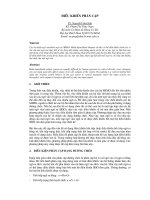
are material constants). Figure
1
shows the
depth of scratches, the deformation depth and the total depth influenced in grinding of steel.
In
an
oblique taper section, the deformed layer becomes visible after etching (fig. 2).
References:
p.
1016.
948
H.
E.
Emer
Ch.
10,
82
20
E
a
Q,
0
0
=
10
3
.I5
-
L
v)
0
-
25
J=
a,
c
n
PO
-
Diamond
-
Grinding
wheels
Emery paper, mesh
size
0
10
20
30
LO
50
60 70
80
Particle
size
,
Nrn
Fig.
1.
Depth
of
roughness,
depth
of
deformation and
total
depth of damage as a
function
of
particle
size
of
the
grinding and polishing medium (after
~ZOW
and
EXNER
[1968]).
2.1.4.
Polishing
In order to prepare a surface free of artefacts, the damaged layer is removed by
polishing.
While
it is relatively easy to obtain scratch-free surfaces, preparation of an
ideally undisturbed surface is difficult if not impossible by mechanical polishing.
As
shown repeatedly (e.g., by
TURLEY
and
SAMUELS
[1981] for copper) mechanically
polished surfaces show all the signs of plastic deformation (shear-bands, recrystallization,
subgrains, etc.) even after prolonged polishing with fine grades
(<
1
pm). The depth of
the remaining disturbance is small
(<
1
pm) and
is
tolerable for most purposes.
Chemical
and
electrolyticpolishing
techniques do not cause deformation. Another technique leaving
little
surface damage is ion-milling or ion-polishing
(LEHTINEN
and
MELANDER
[
1980]),
i.e., sputtering of
the
surface resulting from the impact of energetic argon ions (used
more frequently for preparation of
TEM
foils). Removal of the layer damaged during
grinding by polishing
is
time-consuming.
If
sample preparation
is
not carefully control-
led, deformation from the coarse grinding steps may resist and may influence
not
only
the microscopic appearance
(BUHLER
and
HOUGARDY
[1979],
SMUELS
[1971] and
POKORNY
[
19801) but also X-ray measurements (line broadening, blurring of reflections)
or mechanical tests like indentation hardness and toughness
(BERNST
[
19651 and
EXNER
C1969al). Figure
3
shows the influence of various polishing methods on reflectivity,
which is sensitive to surface damage. Investigations under polarized light suffer from
surface strain as well.
Them1 polishing,
i.e., annealing in vacuo after mechanical
polishing, was shown to produce smooth strain-free surfaces by uniform evaporation
(IRAN1
and
CAHN
[1971]).
Disopolishing using emulsions
of
carefully graded loose diamond or alumina
Ch.
10,
82
Surjace microscopy
949
powders on cloth is the usual way of mechanical polishing. For hard materials, a drill-
like set-up using a wooden stick with diamond paste has advantages. Material removal
is adequate and most materials can be polished this way. Microcutting by diamond blades
has been used as a one-step, time- and labour-saving preparation mode for
soft
materials.
Such
ultrumicrofoming
(for references see
PETZOW
and EXNER
[I9681
and
KLOCKEN-
KAMPER
et
al.
[1979])
has been shown to produce very large localized deformation
(BOCKLE
[1964]);
nevertheless, if the cutting parameters are optimized, a surprisingly
perfect surface quality of microcut metals can be achieved (PETZOW and KNOSP
[1973]
and
PETZOW
and EXNER
[1975]).
By micromilling cross-sections and serial sections of
medium-hard metals and alloys can
be
prepared (KIESSLER and ELSSNER
[1980]
and
PETZOW
and EXNER
[1975]).
There is a nearly infinite number of recipes for chemical and electrochemical
polishing. Reviews are to
be
found in early metallographic standard texts, e.g.,
TEGART
[1957],
PETZOW
and EXNER
[1968],
BIGGS
[1970]
and SHIGOLEV
[1974]
while more
modem references are scarce (METALS
HANDBOOK
[1985],
F'ETZOW
[1994]).
Theoretical
approaches are available (e.g., WAGNER
[1954]
and TOUSEK
[1981],
for reviews and early
references see
PETZOW
and EXNER
[1968]
and BIGGS
[1970]);
however, they do not
allow deduction of optimized polishing procedures for a given material. For electrolytic
polishing, the form of the current density-voltage curve suggests which potentials should
-1
Fig.
2.
Deformed layer in brass (Can
30)
after
cutting by a
new
diamond wheel. Oblique section
(5'
to surface which
is
on the left side). Etched.
200x.
(From
KIESSLER
etal.
[1982].)
100
4-
V
n
95
x
c
>
V
c
-
2
90
0,
a
85
polished
polished
Ni
Ag
Au
Cu
Fig.
3.
Reflectivity (in percent of cleavage surface)
of
metal surfaces polished by different techniques
(after
PETZOW
and
KNOSP
[1973]).
References:
p.
1016.
950
H.
E.
Exner
ch.
10,02
be used to avoid etching effects. (Usually a plateau is observed where polishing occurs.)
It has been shown that these curves should be measured under practical conditions and
not in special cells (R~SCHENBLECK and WOLTER [1979]).
In
spite of the limited exact
theoretical knowledge on the mechanisms of mechanical, chemical and electrolytic
processes, preparation of metallographic cross-sections is not a limiting factor for
microstructural investigations since the
state
of the art allows the investigator to deal with
even the most difficult
materials.
2.1.5. Replica techniques
Surface studies by transmission electron microscopy
are
possible by pressing a foil of
a suitable substance tightly
to
the surface or
to
form a replicating foil by casting
an
organic replica. This technique was used extensively prior to the development of scanning
electron microscopy for high-resolution surface studies. Sample preparation
is
well
developed (see, for example,
GOODHEW
[
19731). By the so-called double-replica
technique, fine precipitates can
be
extracted from a matrix by chemical or electrochemical
etching and embedded in a resin foil. This technique is a quick and reliable standard pro-
cedure for investigating the morphology and the spatial distribution of dispersed particles
and, in particular, is useful for
EDX
analysis
of
small features avoiding signals from the
matrix
(see, for example, SCHR~DER
et
al.
[1990] or CZYRSKA-FILEMONOWICZ
et
al.
[
19921). Replicas can also
be
studied by optical microscopy, scanning electron microsco-
py
(5
3)
and
soft
X-ray microscopy
(§
5.5).
For remote sampling {e.g. for large engineer-
ing components which must not
be
destroyed, for taking samples at temperatures up
to
120°C
or for radioactive materials), replica techniques using movable preparation
equipment
are
frequently the best if not the only way for microscopic inspection (see, for
example,
BLLOUX
[1970], WENDLER and NEUBAUER [1979], BIRNER and
L~HBERG
[1980], or
L~BERT
[1982]). Replication techniques have also been applied in optical and
SEM
fractography, e.g., for the study of stress-corrosion cracking (CONOR [1972]) and fatigue
crack initiation (BROWN and
SMITH
[1982],
DIESER
[1984], or BRUGEL etal. [l988]). Serial
sectioning of plastic replicas is much easier than that of the sample itself, and was proposed
for three-dimensional reconstruction of fracture surfaces
(BAUER
and HALLER [1981]).
2.2. Etching and other contrasting techniques
The human observer is capable of distinguishing between different phases and lattice
defects if these show a grey or colour contrast in microscopic viewing. Polished surfaces
rarely provide sufficient contrast owing to the fairly similar reflectivity of metallic phases, and
contrast enhancement is usually necessary.
A
number
of
metallographic techniques are
available
to
reveal the microstructure.
2.2.1. Chemical and electrolytic etching
When a polished surface is attacked by an etching medium, different phases and
different lattice orientations usually show differing rates of dissolution. Crystal imperfec-
tions and grain boundaries are locations of increased dissolution potential. These
differences in chemical and electrolytic attack
are
the basis for the most frequently
used
ch.
lo,
42
S@me
microscopy
95
1
metallographic techniques for optical contrast enhancement.
In
the monographs by
TEGART
[
19571,
BECKERT
and
KLEMM
[
19841 and
PETZOW
[
1978,19941 or in handbooks
as, for example,
METALS HANDBOOK
[1985], known recipes for technical metals and
alloys are reviewed. Theoretical understanding of material removal (see, for example,
ENGEL
[1958],
SCHAARWI~CHTER
[1968],
BIGGS
[1970],
HERBSLEB
and
SCHWAAB
[1978]), though well-established in corrosion science, is rarely used for finding the
optimum etching conditions for a new material as, for example, in potentiostatic etching
(WORCH
et
al.
[1994]). Usually these are established empirically, aided by educated
guesses. Local changes in reflectivity and shadows produced by the rough topography of
the specimen surface give rise to grey contrast when viewed in the microscope. Thus,
grain boundary grooves and facets, height differences between
grains
of different
orientation and between phases, or etch pits at points where dislocations penetrate the
cross-section, are typical contrast features created by attack-etching. Sometimes, deep-
etching by chemical
or
electrochemical attack may favourably be used to show the
spatial geometry of microstructural features and
to
make them accessible to stereometric
measurement as shown, for example, by
PAUL
and
M~ZRRLE
[1981],
FEIJOO
and
EXNER
[1990], or
FELToo
etaZ.
[1990]
(see
also $2.4.1).
23.2.
Thermal
etching
The thermodynamic instability of a polished surface will lead to effects similar to
those mentioned in $2.2.1 when material transport is activated by heating. The basic
mechanism
is
surface diffusion (rather than selective evaporation), and the kinetics of
thermal grain-boundary grooving and facetting are well understood (see, for example,
MULLINS
[
19611). Thermal etching
is
advantageously used for chemically stable materials
such as ceramics (compare fig. 7c below).
22.3.
Ion-etching
The basis of the well
known
but infrequently used technique of ion-etching, reviewed
by
WECHSUNG
[1977],
POHL
and
BURCHARD
[1980a,b],
GRXF
et
aZ.
[199?],
POHL
[
19941,
PETZOW
[
19941,
PECHENYAKOV
and
KOVACHEVA
[
19951, is cathodic atomization
(sputtering) by bombardment of the surface with chemically neutral (e.g., argon) or
reactive (e.g., oxygen) ions. The physics of sputtering has been surveyed by
OCHSNER
[1975] and by
PIVIN
[198?]. The rate
of
material removal depends on the atomic weights
of
the material and the ions (the highest rates being observed when these are approx-
imately equal), on the energy and density of the ions hitting the surface, and on the
atomic bonding in the material.
By
adjusting the sputtering parameters (voltage, gas
pressure), selective material removal can be made to produce a clear topography and
clean surfaces. Ion-etching
is
advantageously used for composite materials as shown in
fig. 4 and coated metals
(STAPF
et
al.
[1986],
GRAF
et
al.
[1993],
POHL
[1994]).
However, artifacts are easily produced (fig.
5).
Ion etching
is
also useful,
if
the micro-
structure is prepared for the application of surface-sensitive analytical techniques as well
as interference-layer contrasting (see
Q
2.2.5).
References:
p.
101
6.
952
H.
E.
Exner
Ch.
10,
$2
2.2.4.
Staining (tinting) and anodic oxidation
A large number of so-called etching techniques do not produce a surface relief by
dissolving the surface but produce a surface layer by a chemical reaction
(JEGLITSCH
[1968]). These layers vary in thickness as a function of composition and orientation of
the microstructural components. They are transparent and rather than having a specific
colour themselves, produce interference colours varying with thickness,
d.
Light waves
reflected at the surface and at the layer-substrate interface interact, causing extinction of
a specific wavelength
A,
according to the equation (for normal incidence)
2n
m
A,
=
-d,
where
m
determines the order of interference
(m=
1,
3,
5
corresponds to
0,
1,
2
order) and
n
is the refractive index of the deposited layer; for a more detailed discussion
see $2.2.5.
Reaction layers of which the thickness varies with composition of the substrate can
be deposited by chemical attack, by electrolytic processes, e.g. by potentiostatic oxidation
(anodizing), or by oxidation when heating a metallic specimen in air (thermal tinting).
Tinting techniques have been extensively discussed in the literature (see, for example,
JEGLITSCH
[
19681,
GRUTZNER
and
SC~LLER
[
19691,
BERAHA
[
19701,
YANKOVITH
[1970],
BERAHA
and
SPIGHLER
[1977],
HERBSLEB
and
SCHWAAB
[1978],
GAHM
and
JEGLITSCH
[1981],
GAHM
et
al.
[1982],
WECK
and
LEISTNER
[1982-19861,
VANDER
VOORT
[1984a,b, 1985a1,
ZHOU
etal.
[1993],
F’ETZOW
[1994], and many others). Anodic
oxidation is another possibility to produce layers with a thickness varying with orien-
tation and composition of the microstructural features resulting in an orientation- or
phase-specific colour contrast. Anodic oxidation is carried out by immersing the sample
in an acid solution of carefully adjusted pH and applying a voltage in the order
of 100
V.
Intermetallic phases have been identified in this way
(SEEGER
et
al.
[1990]) and the grain
structure of aluminium can be revealed
(YANG
[
1990]), among numerous other applicat-
Fig.
4.
Ionetched cross section of a graphite fibre- Fig.
5.
Artefacts produced by ion-etching of
a
Ni-
reinforced polymer. Scanning electron micrograph,
base
superalloy.
(Cones
formed owing
to
the pres-
300
x
(courtesy
I.
Wf).
ence of non-conducting inclusions). Scanning elec-
tron micrograph,
10,OOO
x
(courtesy
I.
Graf).
Ch.
10,
$2
Surface
microscopy
953
ions (DANIELSON [1985]). In its early days, the colour contrast obtained after depositing
interference layers in the presence of oxygen (reactive sputtering) was also attributed to
varying thickness
(ONDRACEK
and SPIELER [1973]); in fact it depends on a different
optical principle, as discussed in detail in the next section.
23.5.
Interference-layer contrast
A
plane-parallel layer
of
a non-absorbing or weakly absorbing substance acts like
an
optical reflection-interference filter which, by multiple reflection at the metal-layer and
layer-air interfaces, causes contrast enhancement between neighbouring phase regions,
provided these differ in their optical constants. The optical principles of these effects have
been reviewed by
PEPPERHOFF
and ETTWIG [1970],
ZOGG
et
al.
[
19771, B~ER and
HOU-
GARDY
[1979, 19801, BUHLER [1981] or
PETZow
[1994], and a large number of applicat-
ions in metallographic practice have been published (for references see B~ER and
HOUGARDY [1979, 19801, EXNER and
ROTH
[1980],
GAHM
and JEGLITSCH [198l],
GRAP
[1981] and
Wu
et
al.
[1982]). The important factor in interference-layer colour contrasting
is
the phase shift of the light wave reflected at the layer-metal interface. In normal bright-
field microscopy, differences of this phase angle are much too small for metallic phases
to be detectable. The transparent
or
semitransparent layers enhance these differences
dramatically, revealing
a
pronounced colour contrast if two conditions are fulfilled:
(i)
The
phse
condition
relates thickness of the layer
d,
the optical properties of the
metallic phase (phase
shift
of the reflected wave through the angle
8)
and
of
the layer
(refractive index
a),
and the order of interference (defined by
m
as
above) to the
wavelength
A~,
for which interference causes maximum reduction in intensity:
(2)
(ii) The
amplitude
condition
describes the relative intensity
R,,
of the reflected light
&,
=
47rnd/l7r(m
-
1)
-I-
SI.
Usually, the first-order interference
(m
=
1) yields the best results.
with wavelength
A&
For non-absorbing layers,
2
intensity of reflected wave
=
(
q
-
4,
)
%'
=
intensity of incident wave
1
-
q
.
q,
'
(3)
with
2
2
q
=
(n
-
I)/(n
+
I),
4,
=
J(nm
-
n)
+
k:/(n,
+
n)
+
ki
.
n,
and
k,
are the refractive index and the absorption coefficient of the metallic phase,
respectively. Much effort has been undertaken
(B~ER
and HOUGARDY [1979], BUHLER
and KOSSEL 119811, AYJXN and BUHLER [1981, 19841, AYDIN
etal.
[1983] and
B~HLER
[
1986]),
to
determine
n,,,
and
k,
values for phases occurring in metallic materials in order
to be able to calculate the required
n,
A,,
and
d
values for maximum contrast between
phases present in a material. The contrast is defined by
K
=
(R,
-
RJ/R,,
where
R,
and
R2
(R,
>
RJ
are
the relative reflectivities of
two
phases, and reaches a maximum if
R2
=
0,
i.e, when interference causes complete extinction of the colour under consideration in one
References:
p.
1016.
954
H.
E.
Exner
Ch.
10,
$2
of the two phases
(K=
1). If, then, a filter for the corresponding wavelength
A
is used,
this phase appears black. If white light is used, maximum colour contrast will be
obtained.
Plane-parallel interference layers can
be
deposited by evaporation
or
by sputtering. In
order to fulfill the amplitude condition
R,,
=
0,
a non-absorbing layer must have a high
refractive index
if
the substrate has a high reflectivity (as do all metallic phases).
ZnS,
ZnSe, TiO, and ZnTe (n=2.4-3.5) are used for evaporation.
Absorbing
layers can be
deposited by reactive sputtering. This technique, first described by BARTZ [1973], uses
a low gas pressure
(-lo6
bar, usually oxygen) in the sputtering chamber.
A
commercial-
ly
available device
has
proved very useful in practical application
(Bmm
and HOUGAR-
DY
[1979],
Em
and ROTH [1980]) and, at least in principle, allows layers to
be
produced with widely varying optical properties.
A
disadvantage is the fact that calcu-
lating the optimum contrast conditions becomes somewhat more difficult than for non-
absorbing layers
(Zow
et
al.
[
19771).
A
general difficulty is that the quality of surface
preparation before applying the interference layer is crucial
for
the result.
For
example,
scratches
or
contamination by polishing liquids will produce artefacts. Ion polishing,
therefore, is preferable compared to electropolishing
or
mechanical polishing techniques
as
shown,
for
example, for steels by
GAUDIG
and
SCHECK
[1984].
Also,
the accuracy of
measurement of the optical constants depends on the reproducibility of surface prepar-
ation
(KRONER
[1986]). Since calculation
of
optimum contrast conditions can be applied
only
if
the optical constants
are
known to an accuracy of 2% (SCHRODER and HOUGAR-
DY
[1985]), the trial-and-error approach can often be quicker and more practicable. The
reason that interference contrasting is described here more fully than other methods is
that
this
technique
is
still not widely familiar. It has excellent reproducibility and versatil-
ity and could substitute many of the classical contrasting techniques. The extreme sensi-
tivity of the human eye for colour hues and the possibility of using filters makes colour-
contrasting highly attractive. In addition, quantitative evaluation with respect to phase
composition and exact phase identification
(see,
for example,
ZOCG
et
al.
[1977]) are
possible. Care must be taken in the latter cases in photographic reproduction which may
change the original colours appreciably
(CROUSE
et
al.
[1977]
and
EXNER
et
al.
[
19801).
23.
Principles
of
light microscopy and optical contrast enhancement
The highly developed state of the mechanical and optical design
of
microscopes used
in metallographic work makes it impossible to come near to an adequate description in
the context of a book on physical metallurgy.
A
large number
of
monographs (e.g.,
PAYNE
[1957],
0ETl"EL
[1959],
MALES
[1959],
FREW
[1960, 19691,
KINGLAKE
[1965],
BIGGS [1970],
LOVELAND
[1970],
PHILIPS
[1971],
GALOPM
and
HENRY
[1972],
MODIN
and
MODIN
[1973], BEYER [1974], ROST [1981],
BRADBURY
[1991],
SCHADE
[1993])
as
well as articles in handbooks (e.g.,
VANDER
VOORT
[1985b],
LOUTHAN
[1987],
Scr-ru-
MANN
[1990],
TELLE
and PETZOW [1992] or
HOLIK
[1993]) are available which treat the
basic
as
well
as
the practical aspects
of
optical microscopy and photography comprehen-
sively. Accordingly, the optical fundamentals (e.g wave optics, properties of lenses and
correction for aberrations) or the various components of the optical microscope (illumi-
Ch.
10,
$2
Surjzce
microscopy
955
nation systems and light sources, objectives and eyepieces, polarizers, interferometric
attachments, phase contrast equipment, stages etc.) need not be discussed in detail here.
Important features
are
the resolution limit, depth of focus, and the different ways to
enhance contrast by optical manipulations.
2.3.1.
Resolution and depth of focus
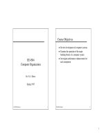
Figure
6
shows the
limiting resohtion
(minimum distance between
two
points and
maximum number of lines per unit length, seen as separate features) and the
depth
of
focus
as
a function
of
the objective’s numerical aperture
n
sina (where
n
is the refractive
index
of
the medium between the objective’s front lens, e.g.,
1
for
air, 1.25 for cedar oil,
and
a
is half the opening angle of the objective; thus,
n
sina is a quantitative measure
for the amount of light reaching the objective). The resolution limit is, in theory,
d=0.6
A/nsinar, where
A
is the wavelength used (Abb6 limit). For green light
(A
=
500
nrn) using an immersion oil between specimen and high-power objective (resulting
in
a numerical aperture
n
sina
=
1.25), we get
d=0.24
pm.
In
practice, however,
the
resolution limit
is
close
to
1
pm even if the illumination system as well as all the lenses
and apertures are optimally adjusted. Magnifications between
500
and 1000 times the
numerical aperture,
i.e.,
up
to
lOOOx,
are useful while higher magnifications yield no
additional information and therefore are called empty magnification. The depth of focus
is inversely proportional to the square of the numerical aperture and is extremely limited
at high magnifications (approx. 0.1 pm).
2.33.
Bright-field illumination
By far the majority of microstructural investigations by optical microscopy
are
carried
out with vertical illumination, usually called
bright $eZd,
and most optical micrographs
of metallic materials are taken this way. Regularly reflected light is used and no
additional manipulations of the light beam are necessary. Thus, high light intensities
are
obtained. The instrumentation is rather simple, and the use does not require great skill.
The contrast is a result of locally varying light intensity due to one of the pretreatments
of
the
specimen section discussed above. The human eye can differentiate between two
grey levels
if
the
contrast
K
is approximately
0.2,
Le.,
five grey levels between black and
white
are
easily distinguishable. Photomultipliers and television cameras are more
sensitive, and more than a hundred grey levels can be registered. If higher contrast is
needed, one of the special techniques described in the next four sections (sometimes
improperly called “optical etching”) can be useful.
2.3.3.
Oblique
illumination, dark field and stop contrast
If
the
direction
of
the incident light is changed from vertical to oblique, the contrast
can
be
reversed with
a
gain
in
contrast which, for suitable specimen surfaces,
is
often
striking. This can be achieved by simply moving the condenser aperture slightly off the
optical
axis,
which produces a shadow-like contrast. While such
oblique illumination
is
only applicable for low magnifications (long-working-distance objectives), a very useful
alternative
is
dark-$eld illurnination:
The
light from the light source does not pass
through the objective but is reflected to the surface by a ring-shaped mirror or lens
References: p.
1016.
956
H.
E.
her
Ch.
10,
$2
0
0.5
1
#O
1.5
Numerical aperture
Fig.
6.
Theoretical resolution (resolved lines
per
mm
and distance between
two
distinguishable points) and
depth
of
focus as
a
function of
the
objective’s numerical aperture (theoretical for green light).
around the objective
so
that only stray (diffusely reflected) light reaches the objective.
Rough surfaces, fissures, pores, grain boundaries and other surface irregularities are
revealed, appearing bright on a dark background. This technique also lends itself for
checking the quality of polish since scratches clearly show
as
bright lines.
Opaque-stop
microscopy produces images similar to dark field. Instead of changing the illumination,
a ring stop is placed between the light source and the condenser lens.
By
moving the
stop, different areas may be illuminated. Tilt angles with respect to flat portions of the
specimen surface have been measured,
for
example during studying tilt and twist
boundaries
(BIGGS
[1970]).
This
is possible to a high degree
of
accuracy (depending on
magnification,
of
the order of
1’
to
60’
of
arc). For qualitative inspection, opaque-stop
microscopy provides a sensitive
type
of
dark-field contrast at no loss in resolution.
2.3.4.
Polarized-light
microscopy
Plane-polarized light (produced by placing a polarizer in front of the condenser lens)
vibrates in one plane only. When reflected from
an
optically isotropic surface, the direct-
ion
of
polarization does
not
change and will be transmitted by an analyzer placed behind
the eyepiece and set parallel
to
the polarizer.
If
the analyzer is rotated, the transmitted
light intensity is reduced and ideally drops to zero at crossed position of polarizer and
analyzer.
If
the plane-polarized beam is reflected by an optically anisotropic surface it is
sub-divided into two components vibrating at right angles to each other. The intensities
of
the components vary as a function of crystallographic orientation and its relation to
the plane
of
polarization. Therefore, the amount of light transmitted by the analyzer is a
Ch.
10,
$2
Surface
microscopy
957
function of the orientation of a crystal which causes changes in brightness
(degree
of
extinction)
when the specimen stage is rotated or, for a polycrystalline material, for the
various crystals when viewed with crossed polarizers. Furthermore, some optically
anisotropic substances (e.g., nonmetallic inclusions such as cuprous oxide) show
distinctly different tints in white polarized light due to an optical effect called
rejection
pleochroism,
owing
to
a variation of reflectivity with wavelength or degree of extinction.
The tint and its change when rotating the analyzer or the stage are characteristic for such
materials.
Polarized light is particularly useful in metallography for differentiating between
optically isotropic and anisotropic components of the structure and for revealing the grain
structure and twins in anisotropic metals and alloys, such as Zn,
Mg,
Ti and V. Though
it is difficult to achieve
a
polished surface which is wholly strain-free, some metals
which
are
hard
or
impossible
to
etch can
be
effectively examined
(IRANI
and
CAHN
[1971]). Even the cubic crystals can become optically active if etch pits or grooves are
produced by etching (for references see
PHILLIPS
[1971])
or
by coating with an aniso-
tropic film e.g., by anodizing
or
by other epitaxially grown
films.
Comprehensive
reviews on the use of polarized reflected light as
an
aid in metallography (and mineral-
ogy)
are
available (CONN and BRADSHAW [1952],
HARTSHORNE
and STUART [1952],
Mom
[1952], PHILLIPS [1971],
GALOPIN
and HENRY [1972], MODIN and MODIN [1973],
MCCRONE
etai.
[1978],
SCHUMANN
[1990],
TELLE
and
PETZOW
[1992], among others).
The quantitative use of polarized light has been restricted mainly to transmitted light in
the fields of petrography and biology, though various measurements are possible in
reflection
on
metals as well.
A
special application is the imaging
of
magnetic domains
in metal crystals making use
of
the Kerr effect, reviewed by BOWMAN and BOOTH
[1971]. The contrast which results
from
a rotation
of
polarization direction by only
I' to
20'
of
arc can
be
improved by interference layers (see
5
2.2.5).
23.5.
Phase contrast and interference contrast
Before some of the modern sample preparation techniques (e.g., interference-layer
deposition
or
reproducible electrolytic etching) were fully developed, optical techniques
transforming phase-angle
or
height differences into grey
or
colour contrast gained some
interest
in
metallography (JEGLITSCH and MITSCHE [1967], BEYER [1974], MODIN and
MODIN [1973], VANDER VOORT [1985b],
SCKUMANN
[1990],
TELLE
and PETZOW [1992]
or
HOLIK [1993]). Though they
are
developed more than
30
years ago, they are now
available with some higher-priced metal microscopes, and have been described in detail
in numerous publications (e.g., OETTEL [1959], JEGLITSCH and MITSCHE [1967] and
BEYER
[
19741) their applications in studying metallic microstructures have remained few.
Phase contrast
(used extensively for transmitted-light studies in biology, see, for
example, YAMAMOTO and TAIRA
[
19831) transforms the invisibly small phase-angle shift
caused by a small difference in height
(or
in optical properties) of an object and its
surrounding into an amplitude (light-intensity) difference visible
to
the human eye.
This
is effected by retarding (positive phase contrast)
or
accelerating (negative phase contrast)
a portion of the directly reflected wave by half a wavelength by inserting a phase
platelet. Interference
of
this
modified reflected wave
from
the phase object with the
References:
p,
1016.