electric machine Chapter 5 Synchronous Machines
Bạn đang xem bản rút gọn của tài liệu. Xem và tải ngay bản đầy đủ của tài liệu tại đây (805.79 KB, 22 trang )
Chapter 5 Synchronous Machines
Main features of synchronous machines:
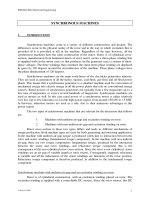
A synchronous machine is an ac machine whose speed under steady-state conditions is
proportional to the frequency of the current in its armature.
The rotor, along with the magnetic field created by the dc field current on the rotor,
rotates at the same speed as, or in synchronism with, the rotating magnetic field produced
by the armature currents, and a steady torque results.
Figure 4.12 Schematic views of three-phase generators: (a) two-pole, (b) four-pole, and
(c) Y connection of the windings.
§5.1 Introduction to Polyphase Synchronous Machines
Synchronous machines:
Armature winding: on the stator, alternating current.
Field winding: on the rotor, dc power supplied by the excitation system.
Cylindrical rotor: for two- and four-pole turbine generators.
Salient-pole rotor: for multipolar, slow-speed, hydroelectric generators and for most
synchronous motors.
Acting as a voltage source:
Frequency determined by the speed of its mechanical drive (or prime mover).
The amplitude of the generated voltage is proportional to the frequency and the field
current.
tNk
tNk
mepphw
mpphwa
ω
ωλ
cos
2
poles
cos
Φ=
⎟
⎟
⎠
⎞
⎜
⎜
⎝
⎛
⎟
⎠
⎞
⎜
⎝
⎛
Φ=
(4.45)
1
mme
2
poles
ωω
⎟
⎠
⎞
⎜
⎝
⎛
= (4.46)
tNkt
dt
d
Nk
dt
d
e
mepphwmeme
p
phw
a
a
ωωω
λ
sincos Φ−
Φ
== (4.47)
tNke
mepphwmea
ω
ω
sin
Φ
−
= (4.48)
pphwmepphwmemax
2
Φ
=
Φ
= NkfNkE
π
ω
(4.49)
pphwmepphwmerms
2
2
2
Φ=Φ= NkfNkfE
π
π
(4.50)
Synchronous generators can be readily operated in parallel: interconnected power
systems.
When a synchronous generator is connected to a large interconnected system containing
many other synchronous generators, the voltage and frequency at its armature terminals
are substantially fixed by the system.
It is often useful, when studying the behavior of an individual generator or group of
generators, to represent the remainder of the system as a constant-frequency,
constant-voltage source, commonly referred to as an infinite bus.
Analysis of a synchronous machine connected to an infinite bus.
Torque equation:
RFfR
2
sin
2
poles
2
δ
π
FT Φ
⎟
⎠
⎞
⎜
⎝
⎛
−= (5.1)
where
= resultant air-gap flux per pole
R
Φ
f
F = mmf of the dc field winding
RF
δ
= electric phase angle between magnetic axes of
R
Φ
and
f
F
The minus sign indicates that the electromechanical torque acts in the direction to
bring the interacting fields into alignment.
In a generator, the prime-mover torque acts in the direction of rotation of the rotor,
and the electromechanical torque opposes rotation. The rotor mmf wave leads the
resultant air-gap flux.
In a motor, the electromechanical torque is in the direction of rotation, in opposition
to the retarding torque of the mechanical load on the shaft.
Torque-angle curve: Fig. 5.1.
Figure 5.1 Torque-angle characteristics.
2
An increase in prime-mover torque will result in a corresponding increase in the
torque angle.
: pull-out torque at . Any further increase in prime-mover
torque cannot be balanced by a corresponding increase in synchronous
electromechanical torque, with the result that synchronism will no longer be
maintained and the rotor will speed up. loss of synchronism, pulling out of step.
max
TT =
o
90
RF
=
δ
⇒
§5.2 Synchronous-Machine Inductances; Equivalent Circuits
Figure 5.2 Schematic diagram of a two-pole,
three-phase cylindrical-rotor synchronous machine.
§5.2.1 Rotor Self-Inductance
§5.2.2 Stator-to-Rotor Mutual Inductances
§5.2.3 Stator Inductances; Synchronous Inductance
§5.2.4 Equivalent Circuit
Equivalent circuit for the synchronous machine:
Single-phase, line-to-neutral equivalent circuits for a three-phase machine operating under
balanced, three-phase conditions.
s
L = effective inductance seen by phase a under steady-state, balanced three-phase
machine operating conditions.
ses
LX
ω
= : synchronous reactance
a
R = armature winding resistance
af
e = voltage induced by the field winding flux (generated voltage, internal voltage)
a
I = armature current
a
v = terminal voltage
Motor reference direction:
faasaaa
ˆˆˆˆ
EIjXIRV ++= (5.23)
Generator reference direction:
faasaaa
ˆˆˆˆ
EIjXIRV +−−= (5.24)
3
Figure 5.3 Synchronous-machine equivalent circuits:
(a) motor reference direction and (b) generator reference direction.
ϕ
XXX
+
=
als
(5.25)
al
X = armature leakage reactance
ϕ
X = magnetizing reactance of the armature winding
R
ˆ
E = air-gap voltage or the voltage behind leakage reactance
Figure 5.4 Synchronous-machine equivalent circuit showing air-gap and
leakage components of synchronous reactance and air-gap voltage.
4
§5.4 Steady-State Power-Angle Characteristics
The maximum power a synchronous machine can deliver is determined by the maximum
torque that can be applied without loss of synchronism with the external system to which it is
connected.
Both the external system and the machine itself can be represented as an impedance in
series with a voltage source.
Figure 5.11 (a) Impedance interconnecting two voltages; (b) phasor diagram.
5
φ
cos
22
IEP
=
(5.34)
Z
EE
I
21
ˆˆ
ˆ
−
= (5.35)
δ
j
eEE
11
ˆ
= (5.36)
22
ˆ
EE = (5.37)
Z
j
eZXjRZ
φ
=+= (5.38)
()
ZZ
Z
jj
j
j
j
e
Z
E
e
Z
E
eZ
EeE
IeI
φφδ
φ
δ
φ
−−
−=
−
==
2121
ˆ
(5.39)
() (
ZZ
Z
E
Z
E
I
φφδφ
−−−= coscoscos
21
)
(5.40)
()
2
2
221
2
cos
Z
RE
Z
EE
P
Z
−−=
φδ
(5.41)
()
2
2
221
2
sin
Z
RE
Z
EE
P
Z
−+=
αδ
(5.42)
where
⎟
⎠
⎞
⎜
⎝
⎛
=−=
−
X
R
ZZ
1
tan90
φα
o
(5.43)
()
2
2
121
1
sin
Z
RE
Z
EE
P
Z
−−=
φδ
(5.44)
Frequently,
0and, ≈≈<<
Z
XZZR
α
,
δ
sin
21
21
X
EE
PP ==
(5.45)
Equation (5.45) is commonly referred to as the power-angle characteristic for a
synchronous machine.
The angle
δ
is known as the power angle.
Note that and are the line-to-neutral voltages.
1
E
2
E
For three-phase systems, a factor “3” shall be placed in front of the equation.
The maximum power transfer is
X
EE
PP
21
max,2max,1
== (5.46)
occurring when
.
o
90±=
δ
If 0>
δ
, leads and power flows from source to .
1
ˆ
E
2
ˆ
E
1
ˆ
E
2
ˆ
E
When 0
<
δ
, lags and power flows from source to .
1
ˆ
E
2
ˆ
E
2
ˆ
E
1
ˆ
E
Consider Fig. 5.12 in which a synchronous machine with generated voltage
and synchronous
is connected to a system whose Thevenin equivalent is a
voltage source
in series with a reactive impedance . The power-angle
characteristic can be written
af
ˆ
E
s
X
EQ
ˆ
V
EQ
jX
δ
sin
EQs
EQfa
XX
VE
P
+
= (5.47)
6
Figure 5.12 Equivalent-circuit representation of
a synchronous machine connected to an external system.
Note that ,
21
EEP ∝
1−
∝
X
P
,
21max
EEP
∝
, and .
1
max
−
∝ XP
In general, stability considerations dictate that a synchronous machine achieve
steady-state operation for a power angle considerably less than
.
o
90
7
Figure 5.14 Equivalent circuits and phasor diagrams for Example 5.7.
8
9
10
§5.3 Open- and Short-Circuit Characteristics
§5.3.1 Open-Circuit Saturation Characteristic and No-Load Rotational
Losses
Figure 5.5 Open-circuit characteristic of a synchronous machine.
§5.3.2 Short-Circuit Characteristic and Load Loss
11
Figure 5.6 Typical form of an open-circuit core-loss curve.
(
)
saafa
jXRIE +=
ˆˆ
(5.26)
Figure 5.7 Open- and short-circuit characteristics of a synchronous machine.
Figure 5.8 Phasor diagram for short-circuit conditions.
(
)
laaaR
jXRIE +=
ˆˆ
(5.27)
aca
aga
us
I
V
X
,
,
,
= (5.28)
a
rateda
s
I
V
X
′
=
,
(5.29)
12
Figure 5.9 Open- and short-circuit characteristics showing
equivalent magnetization line for saturated operating conditions.
fO
fO
′′
′
=SCR (5.30)
AFSC
AFNL
SCR = (5.31)
13
Figure 5.10 Typical form of short-circuit load loss and stray load-loss curves.
t
T
R
R
t
T
+
+
=
5.234
5.234
(5.32)
()
2
eff,
ntaturecurrecircuitarmshort
loss loadcircuit short
−
−
=
a
R (5.33)
14
§5.5 Steady-State Operating Characteristics
Figure 5.15 Characteristic form of synchronous-generator compounding curves.
15
Figure 5.16 Capability curves of an 0.85 power factor, 0.80 short-circuit ratio,
hydrogen-cooled turbine generator. Base MVA is rated MVA at 0.5 psig hydrogen.
aa
IVQP =+=
22
powerApparent (5.48)
Figure 5.17 Construction used for the derivation of a synchronous generator capability curve.
asa
IjXVQjP
ˆˆ
+=− (5.49)
asafa
IjXVE
ˆˆˆ
+= (5.50)
22
2
2
⎟
⎟
⎠
⎞
⎜
⎜
⎝
⎛
=
⎟
⎟
⎠
⎞
⎜
⎜
⎝
⎛
++
s
faa
s
a
X
EV
X
V
QP
(5.51)
Figure 5.18 Typical form of synchronous-generator V curves.
16
Figure 5.19 Losses in a three-phase, 45-kVA, Y-connected,
220-V, 60-Hz, six-pole synchronous machine.
17
§5.6 Effects of Salient Poles; Introduction to Direct-And
Quadrature-Axis Theory
§5.6.1 Flux and MMF Waves
18
Figure 5.20 Direct-axis air-gap fluxes in a salient-pole synchronous machine.
(
)
33,3
3cos2
φω
+= tVE
ea
(5.52)
(
)
(
)
(
)
3333,3
3cos21203cos2
φωφω
+=+−= tVtVE
eeb
o
(5.53)
(
)
(
)
(
)
3333,3
3cos21203cos2
φωφω
+=+−= tVtVE
eec
o
(5.54)
Figure 5.21 Quadrature-axis air-gap fluxes in a salient-pole synchronous machine.
Figure 5.22 Phasor diagram of a salient-pole synchronous generator.
§5.3.2 Phasor Diagrams for Salient-Pole Machines
19
Figure 5.23 Phasor diagram for a synchronous generator showing
the relationship between the voltages and the currents.
dlad
XXX
ϕ
+
=
(5.55)
qlaq
XXX
ϕ
+
=
(5.56)
Figure 5.24 Relationships between component voltages in a phasor diagram.
b
a
ab
oa
ao
′
′
=
′
′
(5.57)
aqa
q
IXI
I
XI
ˆˆ
ˆ
ˆ
oa
ba
ab
ao ==
⎟
⎠
⎞
⎜
⎝
⎛
′′
=
′′
(5.58)
qqddaaafa
IjXIjXIRVE
ˆˆˆˆˆ
+++= (5.59)
20
Figure 5.25 Generator phasor diagram for Example 5.9.
21
22