Synchronous Machines
Bạn đang xem bản rút gọn của tài liệu. Xem và tải ngay bản đầy đủ của tài liệu tại đây (163.18 KB, 25 trang )
ENGNG 2024 Electrical Engineering
E Levi, 2000
1
SYNCHRONOUS MACHINES
1. INTRODUCTION
Synchronous machines come in a variety of different constructions and designs. The
differences occur in the physical outlay of the rotor and in the way in which excitation flux is
provided (if it is provided at all) in the machine. Regardless of the type however, all the
synchronous machines have the same construction of the stator. Stator is of cylindrical cross-
section, manufactured from laminated sheets of steel, and it carries a three-phase winding that
is supplied with (in the motor case) or that produces (in the generator case) a system of three-
phase voltages. The three windings that constitute the stator three-phase winding are displaced
in space by 120 degrees around the circumference of the machine. Three-phase voltages have
the phase displacement of 120 degrees.
Synchronous machines are the main work-horse of the electricity generation industry.
They are used as generators in all the hydro, nuclear, coal-fired, gas-fired and oil-fired power
plants. This means that a synchronous generator is a standard machine used for conversion of
mechanical energy into electric energy in all the power plants that rely on conventional energy
sources. Rated powers of synchronous generators are typically from a few megawatts up to a
few tens of megawatts, or even a several hundreds of megawatts. Synchronous machines are
used as motors as well. In this case rated power of a synchronous motor is either relatively
very low (up to few kilowatts) or is in the high power region, from around 150 kW to 15 MW.
In between, induction motors are used as a rule, due to their numerous advantages in this
power region.
The two types of synchronous machines that are relevant for the discussion that follows
are:
1. Machines with uniform air-gap and excitation winding on rotor.
2. Machines with non-uniform air-gap and excitation winding on rotor.
Rotor cross-section in these two types differs and leads to different mechanisms of
torque production. Both machine types are used for both generating and motoring application.
In the machine with uniform air-gap torque is produced solely due to interaction between the
rotor and stator windings (fundamental torque component). In the machine with non-uniform
air-gap, there are two torque components: fundamental torque, produced by the interaction
between the stator and rotor windings, and reluctance torque component that is the
consequence of the non-cylindrical rotor cross-section. Since the rotor is not cylindrical, stator
windings see an air-gap of variable length as rotor rotates. Consequently, magnetic reluctance
is variable and all the inductances of the stator windings are functions of the rotor position.
Reluctance torque component is therefore produced, in addition to the fundamental torque
component.
Synchronous machine with uniform air-gap and an excitation winding on rotor:
Rotor is of cylindrical construction, with an excitation winding placed on rotor. The
excitation winding is supplied with a controllable DC current. Since the rotor rotates, this DC
ENGNG 2024 Electrical Engineering
E Levi, 2000
2
current has to be supplied somehow from the stationary outside world. In the past, slip rings
and brushes were used to connect a stationary DC source to the rotating rotor winding.
Nowadays, so-called brushless excitation systems (or just brushless exciters) are used (these
are beyond the scope of interest here). Synchronous machines with uniform air-gap and
excitation winding on rotor are often termed turbo-machines. They are used both for motoring
application and for generation in coal-, oil-, and gas-fired plants and nuclear plants. Typical
number of magnetic pole pairs is one or two, so that the so-called synchronous speed of
rotation is 3000 rpm or 1500 rpm for 50 Hz stator frequency. Synchronous speed is defined as
nfP fP
ss
==60 2//
ω π
(1)
and this is the so-called mechanical synchronous speed of rotation (that is, actual speed of
rotation). Symbol P stands for the number of magnetic pole pairs (each pole pair consists of
two magnetic poles, one north and one south).
Rotor of a turbo-machine carries, apart from the excitation winding, a short-circuited
multi-phase winding similar to the squirrel-cage winding of an induction motor. The existence
of this winding is crucial for motoring applications since, without it, the machine would not be
capable of starting when connected to a three-phase supply on stator side. It is important
however to emphasise that this winding has no impact on steady-state operation, since no
currents exist in the short-circuited rotor winding (often called damper winding) in steady-
state. The damper winding is important in generation as well, since it has an important role
during transients. Once again, however, it has no impact on steady-state operation and is
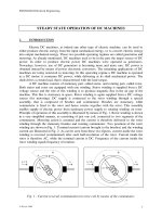
therefore omitted from the schematic representation of a synchronous turbo-machine in Fig. 1,
where only excitation winding is shown on rotor. Stator three phase winding is shown in Fig. 1
with three concentric turns.
It is important to stress once more that an electromagnetic torque in a synchronous
machine with uniform air-gap is produced purely due to the interaction between the stator
currents and the rotor flux (that stems from the DC current in the rotor winding). The torque
consist therefore entirely of the fundamental torque component, very much the same as the
case is with other uniform air-gap machines (DC machines, induction machines). According to
the condition of average torque existence, zero frequency in rotor means that the stator
frequency must equal the frequency of rotation. Rotor flux, produced by rotor DC current, is
stationary with respect to rotor. However, as rotor rotates at the frequency of stator supply,
rotor flux seen from the stator rotates at the same, synchronous, speed as does the stator
rotating field created by the system of stator three-phase currents. Hence all the fields in a
synchronous machine rotate at the same, synchronous speed. Moreover, rotor rotates at the
synchronous speed as well. Note that for the constant frequency of stator voltages there is a
single speed at which the machine can rotate. This means that, regardless of the loading, a
synchronous machine rotates at a constant speed. This is in huge contrast to some other types
of electric machines (DC machines, induction machines) where the speed of rotation is
dependent on the loading of the machine.
Synchronous machine with non-uniform air-gap and excitation winding on rotor:
As already noted, if the air-gap is not uniform, magnetic reluctance (resistance) seen by
windings will vary. In synchronous machines with non-uniform air-gap stator remains to be
cylindrical, but the rotor is not. Consequently, magnetic reluctance seen by stator windings will
vary as the rotor rotates. This gives rise to dependence of stator inductances on instantaneous
rotor position and leads to creation of the second torque component, not present in uniform
ENGNG 2024 Electrical Engineering
E Levi, 2000
3
air-gap machines (reluctance torque component). Since the machine contains an excitation
winding, then a fundamental torque component exists as well, so that the total torque is a sum
of the fundamental torque component and the reluctance torque component.
Rotor
b -c Stator
Air-gap
-a a
c -b Rotor
winding
Fig. 1 - Synchronous machine with uniform air-gap and excitation winding on rotor.
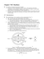
The structure of the machine is shown in Fig. 2. The rotor is of so-called salient-pole
structure and the machine is usually used for very low speed of rotation, so that the number of
poles is very high (say, 84 poles - that is, 42 pole pairs, is a rather common structure). The
machine of Fig. 2 is shown as being of 2-pole structure for simplicity. This type of synchronous
machines is often called hydro-machine or salient-pole synchronous machine, since these
machines are used in hydro-powered electric generation plants. The machine is used in
motoring application as well, for those cases where a low speed of rotation is required.
Rotor of a hydro-machine carries, apart from the excitation winding, a short-circuited
multi-phase winding similar to the squirrel-cage winding of an induction motor (this winding is
not shown in Fig. 2). This is very much the same as for a turbo-machine. This winding once
more has no impact on steady-state operation, since no currents exist in the short-circuited
rotor winding in steady-state (there is not any induced emf, since the rotor rotates at the same
speed as does the stator rotating field).
Rotor
b -c Stator
Air-gap
-a a
Rotor
c-bwinding
Fig. 2 - Cross-section of a salient pole synchronous machine with excitation winding.
ENGNG 2024 Electrical Engineering
E Levi, 2000
4
As already noted, synchronous machines are used as motors either for low power
applications or for very high power applications. In the low power range the advantage of
synchronous motors is their fixed synchronous speed of rotation that is always governed by the
applied frequency in stator winding. In other words, speed of rotation depends only on stator
frequency and it is load independent, in contrast to DC motors and induction motors. As far as
the high power region is concerned, the advantage of synchronous motors over the induction
motors is that they are capable of producing reactive power (while induction motors always
have to consume reactive power). The higher capital cost of a synchronous motor, when
compared to an induction motor of the same size, is thus offset by the capability of the machine
to satisfy its own reactive power needs and, if necessary, to delivery reactive power to the grid
(it is important to realise that reactive power is not for free; industrial customers are charged
for the consumed reactive power).
In what follows, only the synchronous machines with uniform air-gap will be
elaborated. The reason is that an analysis of synchronous machines with non-uniform air-gap is
more involved, due to the existence of the reluctance torque component.
The concept of the rotating fields is reviewed next. This is followed by an explanation
of the mechanism of the reactive power production in a synchronous machine. Motoring mode
of operation and the generating mode of operation are then discussed in two separate sections.
2. ROTATING FIELDS AND REACTIVE POWER BALANCE OF A
SYNCHRONOUS MACHINE
Consider the stator winding of a synchronous machine. Suppose that the machine
operates as a motor, supplied with a system of three phase currents
() ()
iI t iI t iI t
am b m c m
==−=−cos cos / cos /
ωωπ ωπ
23 43
(2)
These currents are delivered by the grid and can be regarded as being impressed into the three
windings, that are spatially displaced along the circumference of the stator by 120 degrees.
Current flow in each of the three phases causes an appropriate m.m.f., that acts along the
magnetic axis of the given phase. The situation is illustrated in Fig. 3, where individual phase
m.m.f.’s are given with (N is the number of turns per phase):
()
()
FNI t
FNI t
FNI t
am
bm
cm
=
=−
=−
cos
cos /
cos /
ω
ωπ
ωπ
23
43
(3)
a
c
b
F
a
F
b
F
c
b
c
a
Fig. 3 - Individual phase m.m.f.’s of a three-phase winding.
ENGNG 2024 Electrical Engineering
E Levi, 2000
5
One observes that in terms of spatial dependence, all the three individual phase magneto-
motive forces are stationary and they act along the defined magnetic axis of the winding. From
(3) one notices that each of the three m.m.f.’s is varying in time. The values of the three phase
m.m.f.’s in the given instant of time correspond to those met in any three phase system.
The resultant magneto-motive force that stems from the three phase system of currents
flowing through spatially displaced windings is the sum of the individual contributions of the
three phases. The summation is done in the cross-section of the machine, and it is necessary to
observe the spatial displacement between the three m.m.f.’s. One may regard the cross-section
of the machine as a Cartesian co-ordinate system in which phase a magnetic axis corresponds
to x-axis, while y-axis is perpendicular to it. For the purposes of calculation this co-ordinate
system may be treated as a complex plane, with x-axis corresponding to the real axis, and y-
axis corresponding to the imaginary axis. In terms of the complex plane, spatial displacement
of the m.m.f. by 120 degrees corresponds to the so-called ‘vector rotator’,
()
aj= exp /23
π
.
Hence the resultant magneto-motive force can be written as
()
()()
()
FFFF e e
FNI t t t
res a b c
jj
res m
=++ = =
=+−+−
aa a a
aa
2
2
3
2
4
3
2
23 43
π π
ωωπ ωπ
,
cos cos / cos /
(4)
The expression for the resultant magneto-motive force is most easily found if one recalls the
well-known correlation
()
cos . exp( ) exp( )
δδδ
=+−05 jj
. Hence
()() () ()
( )
()
()
FNIee ae ae ae ae
FNIeeaaeaaeaaeaae
aa
aa a a a aa
FNIe aaaae
res
jt jt jt jt jt jt
res m
jt jt jt jt jt jt
res m
jt jt
=+++ + + =
++ + + +
++ =
====
=++++
−−−− −−−
−− −
−
1
2
1
2
10
1
1
2
11
23 23
2
43
2
43
22 22
2
22 3 4
22
ω ω ωπ ωπ ωπ ωπ
ωω ω ω ω ω
ωω
/// /
**
**
=
()
()
() ()
()
aa
FNIe e
FNIe
res m
jt jt
res m
jt
2
1
2
30
3
2
+=
=+
=
−
ωω
ω
(5)
Symbol * in (5) stands for complex conjugate. The result obtained in (5) is an important one.
The equation
FNIe
res m
jt
=
3
2
ω
(6)
describes a circular trajectory in the complex plane. This means that the resulting magneto-
motive force, produced by three stationary, time-varying m.m.f.’s (often called pulsating
m.m.f.’s) is a time-independent and rotating magneto-motive force. Thus it follows that the
three-phase system creates a rotating field (called also Tesla’s field) in the machine. Figure 4
illustrates the rotating field in different instants of time. The speed at which the rotating field
travels equals the angular frequency of the stator three-phase supply.
ENGNG 2024 Electrical Engineering
E Levi, 2000
6
Im
ω
t=90
°
ω
t=135
°
F
res
ω
t=45
°
ω
t=0
°
Re (a)
1.5NI
m
Fig. 4 - Resultant field in the three-phase machine for sinusoidal supply conditions.
Since the rotor winding carries excitation current, a field is produced by this current.
This field is stationary with respect to rotor. Since the rotor rotates at synchronous speed,
then, looking in from stationary stator, this rotor field rotates at synchronous speed. This is
always the case in any multi-phase AC machine: regardless of whether the rotor rotates
synchronously or asynchronously, all the fields in the machine rotate at synchronous speed.
Since the resulting m.m.f. is responsible for the resulting flux density and ultimately
resulting flux, this means that apart from the rotating m.m.f., there is a rotating flux density
wave and a rotating flux in the machine as well. The term rotating field in general denotes any
of the three.
In other to show how a synchronous machine can produce reactive power, consider the
operation of a synchronous motor. The motor will always consume real power; however, it can
either generate or absorb reactive power. Let us further consider a couple of characteristic
situations. Let us assume at first that a synchronous motor operates under ideal no-load
conditions, so that all the losses in the motor can be neglected. This means that the input real
power and the output mechanical power are both zero. Such an ideal situation is useful in
explaining the reactive power production and consumption.
Suppose at first that the rotor current is zero. Therefore the rotor does not produce any
rotating field. Rotating field of the stator is generated due to current flow in stator and the
stator rotating field equals the total rotating field of the machine (total field is a vectorial sum
of the field generated by the stator currents and the rotor field; it is fixed since the supply
voltage is fixed, and does not depend on individual values of the rotor and stator fields). Since
rotor current is zero, there is not an induced emf in the stator winding due to rotor flux. Under
these conditions the machine behaves like a pure reactance and consumes reactive power. The
situation is illustrated in Fig. 5a, where total field and stator rotating field are shown for one
instant in time. If the reactance of a stator phase winding is X
s
, then the current in one phase is
I=V/X
s
, where V is the rms of the phase to neutral voltage. Hence the reactive power
consumedbythemachineisQ=3VI=3V
2
/X
s
.
Suppose next that rotor current is now increased to a certain value, say, such that the
emf in the stator winding equals one half of the applied phase to neutral voltage. The situation
is illustrated in Fig. 5b. The stator field is now just one half of the value for zero rotor current,
since one half of the total field is provided by rotor. The current in stator is I = (V - E) /X
s
,and
ENGNG 2024 Electrical Engineering
E Levi, 2000
7
since E is 0.5V, then I = 0.5V/X
s
. Consequently, reactive power consumed by the machine
becomesQ=3VI=1.5V
2
/X
s
. The consumed reactive power is just one half of what it was
originally.
Let the rotor current be now exactly such that the induced emf in stator due to rotor
flux equals applied voltage. This means that the total field exactly equals rotor field and, since
there is not any current in stator, stator field is zero (Fig. 5c). As the stator current is zero, the
machine now neither consumes nor delivers the reactive power.
Finally, let the rotor current be further increased, so that the induced emf becomes
1.5V. The corresponding rotor filed is now larger than the total field and consequently stator
field has to change the direction (Fig. 5d). This means that the stator current now flows from
the machine towards the grid, i.e. I = (V - E) /X
s
= -0.5V/X
s
. Hence the reactive power is now
equal to Q = - 1.5V
2
/X
s
, where negative sign indicates that the reactive power is delivered to
the grid rather than being absorbed.
In all the cases discussed so far stator current was purely reactive and the reactive
power was either taken from or delivered to the grid. If a synchronous machine absorbs
reactive power it is said that it operates in under-excited mode. If a synchronous machine
delivers reactive power to the grid, it is said that it operates in over-excited mode. These two
terms are exclusively related to the reactive power balance of the machine. One notes that for
all these cases the angle between the total rotating field and the rotor rotating field in the
machine is zero.
3. MOTORING MODE OF OPERATION
Suppose now that the synchronous motor drives a load torque. Hence it delivers
mechanical power at the shaft and consequently consumes real (active) power at stator winding
terminals. Let the rotor current be such that the machine is in over-excited mode (Fig. 5d).
What now happens is that an angular displacement occurs between the rotor field and total
field. This angle is called load angle and it is illustrated in Fig. 6, where motoring operation in
over-excited mode is depicted. This load angle will appear in the phasor diagram later on. As
will be shown, power delivered by a synchronous motor directly depends on the value of this
angle.
On the basis of considerations in the previous section, it is easy to derive an equivalent
per-phase representation of the synchronous motor. The applied stator phase to neutral voltage
(note that the value given is always line to line voltage and that stator winding of a
synchronous motor is always connected in star) can be represented with a corresponding
phasor. This voltage phasor corresponds to the total field in Fig. 6. Rotor current causes rotor
flux, that rotates at synchronous speed and therefore induces an emf in the stationary stator
winding. This emf corresponds to the rotor field in the Fig. 6. Hence, in phasor diagram, the
angle between the grid voltage and the induced emf will be equal to the load angle of Fig. 6.
Thus equivalent circuit contains an internal voltage source (induced emf) and the external
applied voltage. In between is the stator reactance of the machine, called synchronous
reactance. Stator winding resistance can usually be neglected and it is omitted from all the
further considerations. Furthermore, iron loss (that takes place in stator core) and mechanical
loss will be neglected as well, so that under these idealised conditions input active power
equals output mechanical power. Equivalent circuit of a synchronous motor with excitation
winding on rotor and uniform air-gap is shown in Fig. 7.
ENGNG 2024 Electrical Engineering
E Levi, 2000
8
F
total
F
s
(= F
res
)
ω
Phase a axis
a.
F
total
F
s
(= F
res
)
F
r
ω
Phase a axis
b.
F
total
F
r
ω
Phase a axis
c.
F
s
F
total
F
r
ω
Phase
a
axis
d.
Fig. 5 - Illustration of rotating fields in a synchronous motor (for ideal no-load conditions)
for four different values of the rotor current.
F
s
F
total
F
r
δ
ω
Phase
a
axis
Fig. 6 - Rotating fields in motoring operation in over-excited mode.
jX
s
I+
VE
Fig. 7 - Equivalent circuit of a synchronous motor.
ENGNG 2024 Electrical Engineering
E Levi, 2000
9
The following phasor equation follows directly from Fig. 7:
EjXI
s
=+
(7)
The phasor diagram, that this equation describes, is drawn in Fig. 8 for two cases: operation in
the under-excited mode when the power factor is lagging (since the machine consumes reactive
power) and operation in the overexcited mode when the power factor is leading (since the
machine consumes active power but simultaneously delivers reactive power to the grid).
jX
s
I
VjX
s
I
VE
δ
E
φδ
φ
II
lagging power factor leading power factor
Fig. 8 - Phasor diagram for motoring operation in under-excited and overexcited modes.
Phasor diagrams of Fig. 8 are used most frequently to determine the unknown load
angle and the induced emf on the basis of the known motor loading and stator terminal
conditions. They simultaneously represent the starting point in deriving the so-called load angle
characteristic of a synchronous motor. Consider the phasor diagram of Fig. 8 for overexcited
mode, that is for convenience re-drawn in Fig. 9. Due to the correlation that exists, one
immediately recognises that the angle BCA is equal to the power factor angle (angle between
current and voltage phasors). On the other hand, angles ODA and ABC are right angles. When
solving the phasor diagram of Fig. 9, it is much easier to use one of the two triangles (triangle
ODC or triangle OBC) and project the phasors on the sides of these two triangles, than to
directly solve the complex phasor equation (7).
In order to obtain the load angle characteristic of a synchronous motor one considers
the triangle OBC in Fig. 9. By projecting the phasors on sides OB and CB one has
C
B
φ
AjX
s
I
D
VE
φδ
I
O
Fig. 9 - Phasor diagram for derivation of load angle characteristic.
ENGNG 2024 Electrical Engineering
E Levi, 2000
10
XI E
XI E
s
s
+=
=
sin cos
cos sin
φ δ
φδ
(8)
When terminal voltage, stator current and the power factor are known, these two equations
enable simple calculation of the load angle and the induced emf. However, for the purpose of
deriving the load angle characteristic one expresses the active stator current component from
the second equation of (8) as
I
E
X
s
cos
sin
φ
δ
=
(9)
Next, it is necessary to recall that the phasor diagram represents one phase of the machine and
that the machine is three-phase. Hence the input active power and the reactive power (that is
either absorbed or delivered, as in Fig. 9) are given in terms of phase to neutral voltage and
phase current as
PVI QVI==33cos sin
φ φ
(10)
Load angle characteristic of a synchronous machine relates the active power with the load
angle, δ. Note that, since the stator resistance loss and the rotational losses are neglected, input
active power equals active power transferred from stator to rotor and it ultimately equals the
output mechanical power. Substitution of (9) into (10) yields
PVI V
E
X
VE
X
ss
== =33 3cos
sin
sin
φ
δ
δ
(11)
The correlation between real (or output) power and load angle is called load angle
characteristic of a synchronous motor. One observes from (11) that, for the given stator
voltage and rotor current (that is, emf) power depends only on the sine of the load angle. This
means that, higher the load is, higher the value of the load angle will be, and vice versa. In
other words, rotor field in Fig. 6 will lag the total field more and more as the loading of the
machine increases.
The maximum power that a synchronous motor can deliver is met when load angle
equals 90 degrees. Hence, for each rotor current setting (that is, for each value of the emf)
there is a maximum power that the motor can deliver. The maximum power is
P
VE
X
s
max
= 3
(12)
If the power required by the load increases above the maximum power, load angle would go
over 90 degrees and the so-called loss of synchronism would take place. Since increase of the
load angle above 90 degrees leads to decrease of the motor power (compared to maximum
power) rather than an increase, power demanded by the load cannot be met and the motor
becomes unstable (it looses synchronism, that is, the speed starts decreasing). The stable
operation of the motor is therefore possible only for load angle values between zero and 90
degrees.
Torque of the motor can be directly obtained from the load angle characteristic by
dividing the power with the mechanical synchronous angular speed of rotation:
T
P
V
E
XfP
P
f
VE
X
TP
f
VE
X
e
ss s
e
s
== =
=
ω
δ
ππ
δ
π
3
1
2
3
1
2
3
1
2
sin
sin
max
(13)