Merlin gerin circuit breaker application guide
Bạn đang xem bản rút gọn của tài liệu. Xem và tải ngay bản đầy đủ của tài liệu tại đây (2.23 MB, 212 trang )
Merlin Gerin
Circuit breaker
application guide
MM M M
M M M M
M M M M M
M
E
R
L
IN
G
E
R
IN
multi 9
C6
0N
C
63
4
0
0
V
a
6
0
0
0
2
4
2
3
4
2
4
10
kA
IE
C
9
47
.2
O - OFF
O - OFF
O - OFF
O - OFF
6
8
1
3
5
7
M
E
R
L
I
N
G
E
R
I
N
m
ulti 9
C60N
C
25
2
3
0
V
a
6
0
0
0
2
4
1
7
8
O - OFF
10 kA
IEC
947.
2
M
E
R
L
IN
G
E
R
IN
multi 9
C
60N
C
63
4
0
0
V
a
6
0
0
0
2
4
2
3
4
2
4
10
kA
IE
C
9
47
.2
O - OFF
O - OFF
O - OFF
O - OFF
6
8
1
3
5
7
1
.5
2
3
4
5
6
8
10
xI
r
I
m
.6
3
.7
.8
.
85
.
9
.9
5
.
9
8
1
xI
n
I
r
S
T
R
2
2
S
E
9
0
1
0
5
%
I
r
a
l
a
r
m
Im
Ir
I
n
=
2
5
0
A
250N
P
9
3
0
8
3
OFF
M
E
R
L
I
N
G
E
R
I
N
c
o
m
p
a
c
t
N
S
2
5
0
N
U
i
7
5
0
V
.
U
i
m
p
8
k
V
.
2
2
0
/
2
4
0
3
8
0
/
4
1
5
4
4
0
5
0
0
6
6
0
/
6
9
0
2
5
0
8
5
3
6
3
5
3
0
8
5
0
c
a
t
A
I
E
C
9
4
7
-
2
U
T
E
V
D
E
B
S
C
E
I
U
N
E
N
E
M
A
U
e
(
V
)
I
c
u
(k
A
)
I
c
s
=
1
0
0
%
I
c
u
1
6
0
/
2
5
0
A
p
u
s
h
t
o
t
r
i
p
p
u
s
h
t
o
t
r
i
p
250N
P
9
3
0
8
3
1.5
2
3
4
5
6
8
1
0
x
Ir
I
m
.6
3
.7
.8
.
8
5
.9
.9
5
.9
8
1
xI
n
I
r
S
T
R
2
2
S
E
9
0
1
0
5
%
I
r
a
l
a
r
m
I
m
Ir
I
n
=
2
5
0
A
OFF
M
E
R
L
IN
G
E
R
I
N
c
o
m
p
a
c
t
N
S
2
5
0
N
U
i
7
5
0
V
.
U
i
m
p
8
k
V
.
2
2
0
/
2
4
0
3
8
0
/
4
1
5
4
4
0
5
0
0
6
6
0
/
6
9
0
2
5
0
8
5
3
6
3
5
3
0
8
5
0
c
a
t
A
I
E
C
9
4
7
-
2
U
T
E
V
D
E
B
S
C
E
I
U
N
E
N
E
M
A
U
e
(
V
)
Ic
u
(
k
A
)
I
c
s
=
1
0
0
%
I
c
u
1
6
0
/
2
5
0
A
p
u
s
h
t
o
t
r
i
p
p
u
s
h
t
o
t
r
i
p
M
E
R
L
IN
G
E
R
IN
m
u
l
t
i
9
ID
'clic
C
3
2
40
m
A
∆
n
0
,
0
3
0
A
2
3
0
V
a
2
0
5
6
4
2
0
5
6
4
I
D
'
c
l
i
c
b
i
4
0
A
B
S
E
N
6
1
0
0
9
a
3
0
0
0
3
N
1
L
1
3
L
2
I
.
O
N
M
E
R
L
I
N
G
E
R
I
N
m
u
l
t
i
9
N
G
1
2
5
L
I
n
=
1
2
5
A
2
2
0
/
2
4
0
V
3
8
0
/
4
1
5
V
4
4
0
V
5
0
0
V
U
e(V
)
5
0
2
5
1
5
6
I
E
C
9
4
7
.
2
1
8
8
0
6
Ic
u(kA
)
1.
5
2
3
4
5
6
8
1
0
x
Ir
I
m
.6
3
.
7
.
8
.8
5
.9
.95
.9
8
1
x
In
I
r
S
T
R
2
2
S
E
9
0
1
0
5
%
I
r
a
l
a
r
m
I
m
I
r
I
n
=
2
5
0
A
250N
P
9
3
0
8
3
OFF
M
E
R
L
I
N
G
E
R
I
N
c
o
m
p
a
c
t
N
S
2
5
0
N
U
i
7
5
0
V
.
U
i
m
p
8
k
V
.
2
2
0
/
2
4
0
3
8
0
/
4
1
5
4
4
0
5
0
0
6
6
0
/6
9
0
2
5
0
8
5
3
6
3
5
3
0
8
5
0
c
a
t
A
I
E
C
9
4
7
-
2
U
T
E
V
D
E
B
S
C
E
I
U
N
E
N
E
M
A
U
e
(
V
)
I
c
u
(
k
A
)
Ic
s
=
1
0
0
%
Ic
u
1
6
0
/
2
5
0
A
p
u
s
h
t
o
t
r
i
p
p
u
s
h
t
o
t
r
i
p
Ic
µP
>I
r
>I
m
t
e
s
t
fa
u
l
t
S
T
R
5
3
U
E
6
0
7
5
9
0
1
0
5
%
I
r
I
Im
Ir
Io
tr
tm
(
s
)
x
I
n
x
Ir
x
Io
x
In
o
n
I
2
t
o
f
f
(
s
)
a
t
1
.5
Ir
te
s
t
R
t
r
t
m
I
m
I
r
I
M
E
R
L
I
N
G
E
R
I
N
c
o
m
p
a
c
t
NS400 H
U
i
7
5
0
V
.
U
i
m
p
8
k
V
.
U
e
(
V
)
2
2
0
/
2
4
0
3
8
0
/
4
1
5
4
4
0
5
0
0
/
5
2
5
6
6
0
/
6
9
0
1
0
0
7
0
6
5
4
0
3
5
I
E
C
9
4
7
-
2
U
T
E
V
D
E
B
S
C
E
I
U
N
E
N
E
M
A
I
c
u
(
k
A
)
c
a
t
B
I
c
s
=
1
0
0
%
Ic
u
Ic
w
6
k
A
/
0
,
2
5
s
I
n
=
4
0
0
A
.
8
1
.
6
3
.
5
.
9
.
9
3
.
9
5
.
9
8
.
8
8
.
8
5
.
8
1
4
5
6
8
3
2
1
.
5
1
0
4
6
8
1
0
3
2
1
.
5
1
2
.
3
.
3
.
2
.
1
.
2
.
1
0
0
1
2
0
2
4
0
6
0
3
0
1
5
2
4
0
.
9
.
9
3
.
9
5
.
9
8
.
8
8
.
8
5
.
8
1
p
u
s
h
t
o
t
r
i
p
p
u
s
h
t
o
t
r
ip
40
0
250N
P
9
3
0
8
3
1
.5
2
3
4
5
6
8
1
0
xI
r
I
m
.6
3
.7
.
8
.8
5
.9
.
95
.9
8
1
x
In
I
r
S
T
R
2
2
S
E
9
0
1
0
5
%
I
r
a
l
a
r
m
I
m
I
r
I
n
=
2
5
0
A
OFF
M
E
R
L
IN
G
E
R
IN
c
o
m
p
a
c
t
N
S
2
5
0
N
U
i
7
5
0
V
.
U
i
m
p
8
k
V
.
2
2
0
/
2
4
0
3
8
0
/4
1
5
4
4
0
5
0
0
6
6
0
/
6
9
0
2
5
0
8
5
3
6
3
5
3
0
8
5
0
c
a
t
A
I
E
C
9
4
7
-
2
U
T
E
V
D
E
B
S
C
E
I
U
N
E
N
E
M
A
U
e
(
V
)
I
c
u
(
k
A
)
Ic
s
=
1
0
0
%
Ic
u
1
6
0
/
2
5
0
A
p
u
s
h
t
o
t
r
i
p
p
u
s
h
t
o
t
r
i
p
R
e
s
e
t
res
et
A
p
Ig
I
∆n
I
s
d
I
i
I
r
Microlo
gi
c
7
0
I
c
s
=
1
0
0
%
I
c
u
2
2
0
/
4
4
0
5
2
5
6
9
0
1
0
0
1
0
0
8
5
I
c
w
8
5
k
A
/
1
s
N
X
3
2
H
2
c
a
t
.
B
IE
C
9
4
7
-
2
U
T
E
V
D
E
B
S
C
E
I
U
N
E
A
S
N
E
M
A
E
N
6
0
9
4
7
-
2
5
0
/
6
0
H
z
U
e
I
c
u
(
V
)
(
k
A
)
0
1
2
5
3
p
u
s
h
O
F
F
p
u
s
h
O
N
O
O
F
F
d
i
s
c
h
a
r
g
e
d
1
Contents
Description
Circuit breakers and system design
The requirements for electrical power distribution
Safety and availability of energy
Structure of LV electrical power distribution
Functions and technologies of protection devices
Standard BS EN 60947-2
Current limitation
Cascading
Discrimination
Earth leakage protection discrimination
Range of circuit breakers
Discrimination rules
LV discrimination study
Enhanced discrimination and cascading
Supplementary requirements
Transformer information
Cable fault reduction
400Hz operation
DC information
Residual current device selection
Circuit breaker markings
LV switch disconnectors
Technical data
Cascading tables
Discrimination tables
Type 2 co-ordinationtables for motor protection
Co-ordination with Telemecanique busbar
Section
1
2
3
Page
3
55
77
2
1000 kVA
1000 A
M
M
100 A400 A
100 A 160 A
75 kW
16 A
20 kV/400 V
1000 kVA
1600 A
1000 kVA
19 kA
45 kA
60 kA
23 kA
70 kA
main
switchboard
building utilities
lighting, heating, etc.
distribution
board
sub-distribution
switchboard
power distribution
switchboard -
industrial/commercial
non-priority
feeders
priority feeders
distribution
distribution
enclosure
distribution
workshop 1
3
Section 1
System requirements
Circuit breakers and system design
Safety and availability of energy
Structure of LV electrical power distribution
Functions and technologies of protection devices
Standard BS EN 60947-2
Current limitation
Cascading
Discrimination
Discrimination rules
Earth leakage protection discrimination
Coordination of protection devices
Range of circuit breakers
LV discrimination study
Enhanced discrimination and cascading
Page
5
6
7
10
15
19
21
25
26
28
30
43
46
4
Glossary
EDW:
SCPD:
IEC:
BS:
CT:
CU:
MSB:
BBT:
MV:
Isc:
Isc(D1):
Usc:
MCCB:
BC:
Icu(*):
IcuD1(*)
Ue:
Ui:
Uimp:
In:
Ith:
Ithe:
Iu:
Icm:
Icu:
Ics:
Icw:
Ir:
1.05 x Ir:
1.30 x Ir:
Ii:
Isd:
ElectroDynamic Withstand
Short circuit protection device
International Electrotechnical Commission
British Standard
Current transformers
control Unit
Main Switchboard
Busbar Trunking
Medium Voltage (1kV to 36kV)
Short-circuit current
Short-circuit current at the point D1 is installed
Short-circuit voltage
Moulded case circuit-breaker
Breaking Capacity
Ultimate Breaking Capacity
Ultimate Breaking Capacity of D1
Rated operational voltage
Rated insulation voltage
Rated impulse withstand voltage
Rated operational current
Conventional free air thermal current
Conventional enclosed thermal current
Rated uninterrupted current
Rated short-circuit making capacity
Rated ultimate short-circuit breaking capacity
Rated service breaking capacity
Rated short time withstand current
Adjustable overload setting current
Conventional non-tripping current
Conventional tripping current
Instantaneous tripping setting current
Short time tripping setting current
5
The design of LV installations leads to basic protection devices
being fitted for three types of faults:
c overloads
c short-circuits
c insulation faults.
Operation of these protection devices must allow for:
c the statutory aspects, particularly relating to safety of people,
c technical and economic requirements.
The chosen switchgear must:
c withstand and eliminate faults at optimised cost with respect to the necessary
performance,
c limit the effect of a fault to the smallest part possible of the installation in order to
ensure continuity of supply.
Achievement of these objectives requires coordination of protection device
performance, necessary for:
c managing safety and increasing durability of the installation by limiting stresses,
c managing availability by eliminating the fault by means of the circuit-breaker
immediately upstream
The circuit-breaker coordination means are:
c cascading
c discrimination.
If the insulation fault is specifically dealt with by earth fault protection devices,
discrimination of the residual current devices (RCDs) must also be guaranteed.
Safety and availability of energy
are the operator s prime
requirements.
Coordination of protection devices
ensures these needs are met at
optimised cost.
Safety and availability of energy
The requirements of electrical power distribution
6
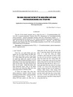
The various levels of an LV electrical installation
Each of the three levels of the installation has specific availability and safety needs.
Structure of LV electrical power
distribution
The requirements of electrical power distribution
Simplified diagram of a standard installation covering most of the cases observed in practice.
1000 kVA
1000 A
M
M
100 A400 A
100 A 160 A
75 kW
16 A
20 kV/400 V
1000 kVA
1600 A
1000 kVA
19 kA
45 kA
60 kA
23 kA
70 kA
main
switchboard
building utilities
lighting, heating, etc.
distribution
board
sub-distribution
switchboard
power distribution
switchboard -
industrial/commercial
non-priority
feeders
priority feeders
distribution
distribution
enclosure
distribution
workshop 1
Level A
Level B
Level C
7
Circuit-breaker functions
This connection device is able to close and break a circuit regardless of current up to
its breaking capacity.
The functions to be performed are:
c close the circuit,
c conduct current,
c open the circuit and break the current,
c guarantee isolation.
The requirements concerning installation, cost optimisation, management of
availability and safety generate technological choices concerning the circuit-breaker.
Level A: the Main Switchboard (MSB)
This unit is the key to the entire electrical power distribution: availability of supply is
essential in this part of the installation.
c Short-circuit currents are high due to:
v the proximity of the LV sources,
v amply sized busbars for conveying high currents.
cc
cc
c This is the area of the power circuit-breakers
Functions and technologies of the
protection devices
Own current compensation
diagram
Protection devices and their
coordination must be suited to
the specific features of the
installation.
c At the main switchboard, the need
for energy availability is greatest,
c At the sub-distribution
switchboards, limitation of stresses
in event of a fault is important,
c At final distribution, user safety is
essential.
1/3
2/3
i
i
A
i
cc
cc
c Main data of these circuit-breakers:
v of industrial type, meeting standard BSEN 60947-2,
v with a high breaking capacity lcu from 40 to 150 kA,
v with a nominal rating of 1000 to more than 5000 A,
v category B:
- with a high lcw from 40 kA to 100 kA — 1 s
- with a high electrodynamic withstand (EDW),
v with a stored energy operating mechanism allowing source coupling.
Continuity of supply is ensured by total discrimination:
v upstream with the protection fuses of the HV/LV transformer (*),
v downstream with all the feeders (time discrimination).
(*) The value of HV/LV discrimination lies above all in the fact that resumption of operation has
fewer constraints in LV (accessibility, padlocking). This offers considerable advantages for
continuity of supply.
These circuit-breakers are designed for high current
electrical distribution:
v they are normally installed in the MSBs to protect
high current incomers and feeders;
v they must remain closed in event of short-circuits so
as to let the downstream circuit-breaker eliminate the
faults. Their operation is normally time-delayed.
ElectroDynamic Withstand (EDW) and high thermal
withstand characterised by a short time withstand
current lcw are essential.
EDW is designed to be as great as possible by an own
current compensation effect.
8
Level B: the subdistribution boards
These boards belong to the intermediate part of the installation:
c distribution is via conductors (BBT or cables) with optimised sizing,
c sources are still relatively close: short-circuit currents can reach 100 kA,
c the need for continuity of supply is still very great.
Protection devices must consequently limit stresses and be perfectly coordinated
with upstream and downstream LV distribution.
This is the area of the moulded case circuit-breakers
These circuit-breakers must open and break the current as quickly as possible. The
main need is to avoid as far as possible stresses at cable and connection level and
even at load level. For this purpose, repulsion at contact level must be encouraged
in order to eliminate the fault even as the current is rising.
Fm
i
i
Fm
The possible diagrams
are:
c with a single repulsion
loop,
c with double repulsion
c with an extractor, a
magnetic core pushing or
pulling the moving
contact.
Example of a repulsion diagram Fm = magnetic force
The repulsion effects can be enhanced by implementation of magnetic circuits:
c with effects proportional to the current square (U-shaped attracting or expulsion
circuit),
c with effects proportional to the current slope (di/dt) and thus particularly effective
for high currents (lsc).
Main data of the moulded case circuit-breakers:
c of industrial type, meeting standard BSEN 60947-2,
c with a high breaking capacity (36 to 150 kA),
c with a nominal rating from 100 A to 1600 A,
c category B for high rating circuit-breakers (> 630 A),
c category A for lower rating circuit-breakers (< 630 A),
c with fast closing and opening and with three operating positions (ON/OFF/
Tripped).
Continuity of supply is ensured by discrimination:
c partial, possibly, to supply non-priority feeders,
c total for downstream distribution requiring high energy availability.
The requirements of electrical power distribution
9
Level C: Final distribution
The protection devices are placed directly upstream of the loads: discrimination with
the higher level protection devices must be provided.
A weak short-circuit current (a few kA) characterises this level.
c This is the area of the Miniature Circuit-breaker
i
i
Fm
i
These circuit-breakers are designed to protect final
loads. The purpose is to limit stresses on cables,
connections and loads.
The technologies for the miniature circuit-breakers,
mainly used at this installation level, prevent such
stresses from occurring.
In miniature circuit-breakers, limitation partly depends
on the magnetic actuator. Once the mechanism has
been released, it will strike the moving contact making
it move at a high speed very early on. Arc voltage thus
develops very quickly at a very early stage. For small
rating circuit-breakers, specific pole impedance
contributes to limitation.
The miniature circuit-breaker is ideal for domestic use
and for the protection of auxiliaries; it then conforms to
standard BSEN 60898.
On the other hand, if it is designed for industrial use, it
must meet standard BSEN 60947-2.
Main data of these circuit-breakers:
cc
cc
c a breaking capacity to match needs (i.e. Below 10 kA on average),
cc
cc
c a nominal rating of 1.5 to 125 A according to the loads to be supplied,
cc
cc
c normally intended for domestic applications: conform to standard BSEN 60898.
The protection devices installed must provide:
cc
cc
c current limitation,
cc
cc
c operating convenience,
cc
cc
c absolute safety,
as these devices are handled by non-specialist users.
10
-Changes in dependability needs and technologies have led to a marked increase in
standard requirements for industrial circuit-breakers. Conformity with standard IEC
947-2, renamed IEC 60947-2 in 1997 and BSEN60 947-2 can be considered as an
all-risk insurance for use of circuit-breakers. This standard has been approved by
all countries.
The principles
Standard BSEN 60947-2 is part of a series of standards defining the specifications
for LV electrical switchgear:
c the general rules BSEN 60947-1, that group the definitions, specifications and
tests common to all LV industrial switchgear,
c the product standards BSEN 60947-2 to 7, that deal with specifications and tests
specific to the product concerned.
Standard BSEN 60947-2 applies to circuit-breakers and their associated trip units.
Circuit-breaker operating data depend on the trip units or relays that control their
opening in specific conditions.
This standard defines the main data of industrial circuit-breakers:
c their classification: utilisation category, suitability for isolation, etc.
c the electrical setting data,
c the information useful for operation,
c the design measures,
c coordination of protection devices.
The standard also draws up series of conformity tests to be undergone by the circuit-
breakers. These tests, which are very complete, are very close to real operating
conditions. Conformity of these tests with standard BSEN 60947-2 is verified by
accredited laboratories.
Table of main data
Voltage Ue rated operational voltage
data Ui rated insulation voltage
Uimp rated impulse withstand voltage
Current In rated operational current
data Ith conventional free air thermal current
Ithe conventional enclosed thermal current
Iu rated uninterrupted current
Short-circuit Icm rated short-circuit making capacity
data Icu rated ultimate short-circuit breaking capacity
Ics rated service breaking capacity
Icw rated short time withstand current
Trip unit Ir adjustable overload setting current
data 1.05 x Ir conventional non-tripping current
1.30 x Ir conventional tripping current
Ii instantaneous tripping setting current
Isd short time tripping setting current
Circuit-breaker category
Category BSEN 60947-2 defines two circuit-breaker categories:
c category A circuit-breakers, for which no tripping delay is provided. This is normally
the case of moulded case circuit-breakers.
These circuit-breakers can provide current discrimination.
c category B circuit-breakers, for which, in order to provide time discrimination,
tripping can be delayed (up to 1 s) for all short-circuits of value less than the current
lcw.
This is normally the case of power or moulded case circuit-breakers with high
ratings. For circuit-breakers installed in the MSBs, it is important to have an lcw
equal to lcu in order to naturally provide discrimination up to full ultimate breaking
capacity lcu.
Standard BSEN 60947.2 specifies
the main data of Industrial Circuit-
Breakers:
c the utilisation category,
c the setting data,
c the design measures,
c etc.
It draws up a series of very
complete tests representative of
circuit-breaker real operating
conditions. In appendix A, it
recognises and defines
Coordination of Protection Devices
— Discrimination and Cascading.
Conformity of a circuit-breaker
with standard BSEN 60947-2 is a
must for industrial BSEN
switchgear.
The requirements of electrical power distribution
Standard BSEN 60947-2
11
Reminders of standard-related electrical data
The setting data are given by the tripping curves.
These curves contain some areas limited by the following currents (defined in
appendix K of standard BSEN 60947-2).
I
t
Io
Icu
Ir
Ii
Isd
t
d
t
sd
c Rated operational current (ln)
ln (in A rms) = maximum uninterrupted current withstand at a given ambient
temperature without abnormal temperature rise.
E.g. 125 A at 40 °C
c Adjustable overload setting current (lr)
lr (in A rms) is a function of ln. lr characterises overload protection. For operation in
overload, the conventional non-tripping currents lnd and tripping currents ld are:
vv
vv
v lnd = 1.05 lr,
vv
vv
v ld = 1.30 lr.
ld is given for a conventional tripping time.
For a current greater than ld, tripping by thermal effect will take place according to an
inverse time curve. lr is known as Long Time Protection (LTP).
c Short time tripping setting current (lsd)
lsd (in kA rms) is a function of lr. lsd characterises short-circuit protection. The circuit-
breaker opens according to the short time tripping curve:
vv
vv
v either with a time delay tsd,
vv
vv
v or with constant l
2
t,
vv
vv
v or instantaneously (similar to instantaneous protection).
lsd is known as Short Time Protection or lm.
c Instantaneous tripping setting current (li)
li (in kA) is given as a function of ln. It characterises the instantaneous short-circuit
protection for all circuit-breaker categories. For high overcurrents (short-circuits)
greater than the li threshold, the circuit-breaker must immediately break the fault
current.
This protection device can be disabled according to the technology and type of
circuit-breaker (particularly B category circuit-breakers).
12
Rated short time withstand
current (ts = 1 s)
Relationship betwenn Icu and
permissible peak current
asymmetrical
peak I
t t
Icu
Id
Id
Icw
ts = 1 s
Table for calculation of asymmetrical short-circuits (BSEN 60947.2 para. 4.3.5.3.)
c Rated short-circuit making capacity(*) (lcm)
lcm (peak kA) is the maximum value of the asymmetrical short-circuit current that the
circuit-breaker can make and break. For a circuit-breaker, the stress to be managed
is greatest on closing on a short-circuit.
c Rated ultimate breaking capacity(*) (lcu)
lcu (kA rms) is the maximum short-circuit current value that the circuit-breaker can
break. It is verified according to a sequence of standardised tests. After this
sequence, the circuit-breaker must not be dangerous. This characteristic is defined
for a specific voltage rating Ue.
c Rated service breaking capacity(*) (lcs)
lcs (kA rms) is given by the manufacturer and is expressed as a % of lcu. This
performance is very important as it gives the ability of a circuit-breaker to provide
totally normal operation once it has broken this short-circuit current three times. The
higher lcs, the more effective the circuit-breaker.
c Rated short time withstand current(*) (lcw)
Defined for B category circuit-breakers
lcw (kA rms) is the maximum short-circuit current that the circuit-breaker can
withstand for a short period of time (0.05 to 1 s) without its properties being affected.
This performance is verified during the standardised test sequence.
(*) These data are defined for a specific voltage rating Ue.
lsc: symmetrical assumed short-circuit asymmetry factor
kA (root mean square value) k
4,5 i I i 6 1,5
6 < I i 10 1,7
10 < I i 20 2,0
20 < I i 50 2,1
50 < I 2,2
The requirements of electrical power distribution
13
t
I
B
I
cu
D1
D2 D1
I
I
cu
D2
D1
D2
overlapping
area
Circuit-breaker coordination
The term coordination concerns the behaviour of two devices placed in series in
electrical power distribution in the presence of a short-circuit.
c Cascading or back-up protection
This consists of installing an upstream circuit-breaker D1 to help a downstream
circuit-breaker D2 to break short-circuit currents greater than its ultimate breaking
capacity lcuD2. This value is marked lcuD2+D1.
BSEN 60947-2 recognises cascading between two circuit-breakers. For critical
points, where tripping curves overlap, cascading must be verified by tests.
c Discrimination
This consists of providing coordination between the operating characteristics of
circuit-breakers placed in series so that should a downstream fault occur, only the
circuit-breaker placed immediately upstream of the fault will trip.
BSEN 60947-2 defines a current value ls known as the discrimination limit such that:
vv
vv
v if the fault current is less than this value ls, only the downstream circuit-breaker D2
trips,
vv
vv
v if the fault current is greater than this value ls, both circuit-breakers D1 and D2 trip.
Just as for cascading, discrimination must be verified by tests for critical points.
Discrimination and cascading can only be guaranteed by the manufacturer who will
record his tests in tables.
E 45015b
t
I
B
I
cu
D2+D1
D2 D1
I
I
cu
D2
D1
D2
Cascading Discrimination
c Glossary:
vv
vv
v lsc(D1): Short-circuit current at the point where D1 is installed,
vv
vv
v lcuD1: Ultimate breaking capacity of D1.
14
Main switchboard Subdistribution switchboard Final distribution switchboard
Level A Level B Level C
Switchboard data
nominal I 1000 to 6300 A 100 to 1000 A 1 to 100 A
Isc 50 kA to 150 kA 20 kA to 100 kA 3 kA to 10 kA
Thermal withstand
*** * *
lcw/EDW
Continuity
*** *** **
of supply
Circuit-breaker High current power Moulded case Miniature
type circuit-breaker circuit-breaker circuit-breaker
or moulded case circuit-breaker
Standard IEC 60947-2 ccc (1)
Trip unit
thermal magnetic v (2) c
electronic cc
product data
standard ln 800 to 6300 A 100 to 630 A 1 to 125 A
Icn 50 kA to 150 kA 25 kA to 150 kA 3 kA to 25 kA
Utilisation category B A A
Limiting capacity
*
(3)
*** ***
cc
cc
c recommended or compulsory
v possible
***
important
**
normal
*
not very important
(1) for domestic use as per BSEN 60898
(2) possible up to 250 A
(3) Sizing of the switchboard at level A means that this characteristic is not very important for standard applications.
Summarising table
The requirements of electrical power distribution
15
t
I
t
Em
t1
t2
U
L
A
ts
Id
asymmetrical
Isc
Principles
The assumed fault current lsc is the short-circuit current lsc that would flow, if there
were no limitation, at the point of the installation where the circuit-breaker is placed.
Since the fault current is eliminated in less than one half-period, only the first peak
current (asymmetrical peak l) need be considered. This is a function of the
installation fault cos ϕ.
Limitation is a technique that
allows the circuit-breaker to
considerably reduce short-circuit
currents.
The advantages of limitation are
numerous:
c attenuation of the harmful effects
of short-circuits:
- electromagnetic
- thermal
- mechanical
c base of the cascading technique.
Reduction of this peak l to limited l
L
characterises circuit-breaker limitation.
Limitation consists of creating a back-electromotive force opposing the growth of the
short-circuit current.
The three decisive criteria guaranteeing the effectiveness of this limitation are:
c intervention time, i.e. the time ts when the back-electromotive force (bemf)
appears,
c the rate at which bemf increases,
c the value of bemf.
The back-electromotive force is the arc voltage Ua due to the resistance of the arc
developing between the contacts on separation. Its speed of development depends
on the contact separation speed.
* As shown in the figure above, as from the time ts when the contacts separate, the
back less than the assumed fault current flow through when a short-circuit occurs.
Limitation
16
A
2
I
2
cc
t
Assumed
energy
100%
Limited
energy
< 1%
t
tcc
100%
10%
Â
assumed transient
peak Isc
limited
peak Isc
assumed steady
peak Isc
Isc
Advantages
c Application to electrical power distribution
Limitation considerably reduces the harmful effects of short-circuits on the
installation.
harmful effects limitation effects
of short-circuits
c electromagnetic Reduction of magnetic field, thus
v less risk of disturbing neighbouring
measurement instruments.
c mechanical Peak current limited, thus:
v reduced electromagnetic forces,
v less risk of deformation or breakage at
electrical contact level.
c thermal Limited thermal stress (reduction of amplitude
and duration of current flow), thus:
v temperature rise of conductors less marked,
v increased lifetime of busbar trunking.
Consequently, limitation contributes to the durability of electrical installations.
Circuit breaker limitation capacity
The circuit breaker limitation capacity defines the way it reduces the let through
current under short-circuit conditions.
The thermal stress of the limited current is the area (shaded) defined by the curve of
the square of the limited current l
2
sc (t).
If there is no limitation, this stress would be the area, far larger, that would be
defined by the curve of the square of the assumed current.
For an assumed short-circuit current lsc, limitation of this current to 10% results in
less than 1% of assumed thermal stress.
The cable temperature rise is directly proportional to the thermal stress (1).
Current and thermal stress limitation
E 45010
The implementation techniques
17
isolation and
short-circuit
protection
control
overload
protection
or thermal
protection
internal motor
or specific
protections
Motor feeder
cc
cc
c Applications to motors Functions
type 1 type 2
BSEN 60947-4-1 BSEN 60947-4-1
No risk for the operator. No damage or malfunctioning is allowed.
Elements other than contactors Isolation must be maintained after an
and the relay must not be damaged. incident and the motor feeder must be able
Isolation must be maintained after to operate after a short-circuit. The risk of
an incident. contactor contact welding is accepted if
contacts can be easily separated. Before
Before restarting, the motor restarting, a quick inspection is sufficient.
feeder must be repaired. Reduced maintenance and rapid
resumption of operation.
The following functions must be performed on a motor
feeder:
v isolation
v control
v overload protection (specific)
v short-circuit protection
v additional protection
A motor feeder can be made up of 1, 2, 3 or 4 different
items of switchgear.
Should a number of devices be associated —most
common case — the various functions performed by the
switchgear must be coordinated.
Coordination of motor feeder components
Thanks to limitation, the harmful effects of short-circuits
on a motor feeder are greatly reduced. Proper
limitation of circuit-breakers ensures easy access to a
type 2 coordination as per BSEN 60947-4-1, without
oversizing of components. This type of coordination
guarantees users optimum use of their motor feeders.
18
Current limitation curve
Thermal stress limitation curve
Limitation curves
A circuit-breaker s limiting capacity is expressed by limitation curves that give:
c the limited peak current as a function of the rms current of the assumed short-
circuit current.
For example: on a 160 A feeder where the assumed lsc is 90 kA rms, the non-limited
peak lsc is 200 kA (asymmetry factor of 2.2) and the limited lsc is 26 kA peak.
c the limited thermal stress (in A
2
s) as a function of the rms current of the
assumed short-circuit current.
For example: on the previous feeder, the thermal stress moves from more than 100
10
6
A
2
s to 6 10
6
A
2
s.
The implementation techniques
kA
90 kA
200
26
limited peak Isc
assumed rms Isc
peak
kA rms
A s
2
90
limited
thermal
stress
assumed
rms Isc
kA rms
19
Cascading provides circuit-breakers placed downstream of a limiting circuit-breaker
with an enhanced breaking capacity. The limiting circuit-breaker helps the circuit-
breaker placed downstream by limiting high short-circuit currents. Cascading makes
it possible to use a circuit-breaker with a breaking capacity lower than the short-
circuit current calculated at its installation point.
Area of application
Cascading:
c concerns all devices installed downstream of this circuit-breaker,
c can be extended to several consecutive devices, even if they are used in different
switchboards.
The installation standards (BS 7671 or IEC 364) stipulate that the upstream device
must have an ultimate breaking capacity lcu greater than or equal to the assumed
short-circuit current at the installation point.
For downstream circuit-breakers, the ultimate breaking capacity lcu to be considered
is the ultimate breaking capacity enhanced by coordination.
Principles
As soon as the two circuit-breakers trip (as from point lB), an arc voltage UAD1 on
separation of the contacts of D1 is added to voltage UAD2 and helps, by additional
limitation, circuit-breaker D2 to open.
Cascading is used to:
c make savings,
c simplify choice of protection
devices, by using circuit-breakers
with standard performance.
t (s)
I
B
I
cu
(D2 + D1)
D2 D1
I
I
cu
(D2)
D1
D2
I
t1
Icc
UAD2
IB
t1'
t2
UAD1
UAD2
UAD1
t (ms)
Cascading
20
D1 helps D2 to break the current
limitation of D2 enhanced by D1
limitation of D2
limitation of D1
IcuD2/enhanced
IcuD2
Icc (D)
I
1
I
D1
D2
The association D1 + D2 allows an increase in performance of D2 as shown in
figure 2:
c limitation curve D2,
c enhanced limitation curve of D2 by D1,
c lcu D2 enhanced by D1.
In actual fact, in compliance with the recommendations of BSEN 60947-2,
manufacturers give directly and guarantee lcu enhanced by the association of D1 +
D2.
Advantages
Cascading allows benefit to be derived from all the advantages of limitation. Thus,
the effects of short-circuit currents are reduced, i.e.:
c electromagnetic effects,
c electrodynamic effects,
c thermal effects.
Installation of a single limiting circuit-breaker results in considerable simplifications
and savings for the entire downstream installation:
c simplification of choice of devices by the cascading tables,
c savings on downstream devices. Limitation enables circuit-breakers with standard
performance to be used.
The implementation techniques
21
D1
D2
0
Is
D2
Ir
D1 and D2
trip
I fault
D2 only
trips
I fault
Discrimination of protection
devices is a key factor in
continuity of supply.
Discrimination is:
c partial,
c or total,
according to the characteristics
of the association of protection
devices.
The discrimination techniques
implemented are:
c current
c time
c logic.
Discrimination can be optimised
by use of current limiting
downstream circuit-breakers.
General information
Principle
Reminder (see paragraph 1.4. "standard BSEN 60947-2").
Discrimination consists of providing coordination between the operating
characteristics of circuit-breakers placed in series such that should a downstream
fault occur, only the circuit-breaker placed immediately upstream of the fault will trip.
A discrimination current ls is defined such that:
lfault > ls: both circuit-breakers trip,
lfault < ls: only D2 eliminates the fault.
cc
cc
c Discrimination quality
The value ls must be compared with assumed lsc(D2) at point D2 of the installation.
v total discrimination: ls > lsc(D2); discrimination is qualified as total, i.e. whatever
the value of the fault current, D2 only will eliminate it.
v partial discrimination: ls < lsc(D2); discrimination is qualified as partial, i.e. up to ls,
only D2 eliminates the fault. Beyond ls, both D1 and D2 open.
cc
cc
c Manufacturer s data
In actual fact, manufacturers give discrimination quality intrinsically, i.e.:
v total discrimination, if ls is equal to lcuD1 (the association will never be able to see
a fault current greater than this value),
v partial discrimination, limited to ls. This value ls can nevertheless be greater than
lsc(D2). Seen by the user, discrimination is then total.
cc
cc
c Glossary
v lsc(D1): Short-circuit current at the point where D1 is installed,
v lcuD1: Ultimate breaking capacity of D1.
Discrimination
22
The discrimination limit ls is:
- ls = lsd2 if the thresholds lsd1 and lsd2 are too close or merge,
- ls = lsd1 if the thresholds lsd1 and lsd2 are sufficiently far apart.
As a rule, current discrimination is achieved when:
- lr1 / lr2 < 2
- lsd1 / lsd2 > 2
The discrimination limit is
- ls = lsd1.
Discrimination quality
Discrimination is total if ls > lsc(D2), i.e. lsd1 > lsc(D2).
This normally implies:
v a relatively low level lsc(D2),
v a large difference between the ratings of circuit-breakers D1 and D2.
Current discrimination is normally used in final distribution.
cc
cc
c Time discrimination
This is the extension of current discrimination and is obtained by staging over time of
the tripping curves. This technique consists of giving a time delay of t to the Short
Time (ST) tripping of D1.
Discrimination techniques
c Current discrimination
This technique is directly linked to the staging of the Long Time (LT) tripping curves
of two serial-connected circuit-breakers.
The thresholds (lr1, lsd1) of D1 and (lr2, lsd2) comply with the staging rules of
current discrimination.
The discrimination limit ls of the association is at least equal to li1, the instantaneous
threshold of D1.
D1
D2
Isd 2 Isd 1
Ir2 Ir1
t
D2 D1
I
Ir1
D1
D2
Isd 2 Isd 2
Ir2
Isd 1
∆t
t
D2 D1
Id
23
Ic
ILd
Id
Id
non-limiting
short-circuit
limiter
Isc (D2)
Discrimination quality
There are two possible applications:
c on final and/or intermediate feeders.
A category circuit-breakers can be used with time-delayed tripping of the
upstream circuit-breaker. This allows extension of current discrimination up to the
instantaneous threshold li1 of the upstream circuit-breaker: ls > li1.
If lsc(D2) is not too high — case of a final feeder - total discrimination can be
obtained.
c on the incomers and feeders of the MSB
At this level, as continuity of supply takes priority, the installation characteristics
allow use of B category circuit-breakers designed for time-delayed tripping. These
circuit-breakers have a high thermal withstand (lcw
> 50% lcn for t = 1s): ls > lcw1.
Even for high lsc(D2), time discrimination normally provides total
discrimination: lcw1 > lsc(D2).
NB: Use of B category circuit-breakers means that the installation must withstand
high electrodynamic and thermal stresses.
Consequently, these circuit-breakers have a high instantaneous threshold li that can
be adjusted and disabled in order to protect the busbars if necessary.
In fact, when referring to the figure, a fault current ld will be seen by D1:
vv
vv
v equal to ld for a non-limiting circuit-breaker,
vv
vv
v equal to lLd
< ld for a limiting circuit-breaker.
The limit of current and time discrimination ls of the association D1 + D2 is thus
pushed back to a value that increases when the downstream circuit-breaker is rapid
and limiting.
Discrimination quality
Use of a limiting circuit-breaker is extremely effective for achievement of total
discrimination when threshold settings (current discrimination) and/or the
instantaneous tripping threshold (time discrimination) of the upstream circuit-
breaker D1 are too low with respect to the fault current ld in D2 — lsc(D2).
c enhancement of current and time discrimination
vv
vv
v limiting downstream circuit-breakers
Use of a limiting downstream circuit-breaker enables the discrimination limit to be
increased.
24
D1
D2
D3
pilot wire
interlocking
order
interlocking
order
The implementation techniques
This type of discrimination can be achieved with circuit-breakers equipped with
specially designed electronic trip units (Compact, Masterpact): only the Short Time
Protection (STP) and Ground Fault Protection (GFP) functions of the controlled
devices are managed by Logic Discrimination. In particular, the Instantaneous
Protection function — inherent protection function — is not concerned.
Settings of controlled circuit-breakers
c time delay: there are no rules, but staging (if any)of the time delays of time
discrimination must be applied
(tD1
> tD2 > tD3)
c thresholds: there are no threshold rules to be applied, but natural staging of the
protection device ratings must be complied with (lcrD1 > lcrD2 > lcrD3).
NB: This technique ensures discrimination even with circuit-breakers of similar
ratings.
Principles
Activation of the Logic Discrimination function is via transmission of information on
the pilot wire:
c ZSI input:
v low level (no downstream faults): the Protection function is on standby with a
reduced time delay (
< 0.1 s).
v high level (presence of downstream faults): the relevant Protection function moves
to the time delay status set on the device.
c ZSI output:
v low level: the trip unit detects no faults and sends no orders.
v high level: the trip unit detects a fault and sends an order.
Operation
A pilot wire connects in cascading form the protection devices of an installation (see
figure showing logic discrimination). When a fault occurs, each circuit-breaker
upstream of the fault (detecting a fault) sends an order (high level output) and moves
the upstream circuit-breaker to its natural time delay (high level input). The circuit-
breaker placed just above the fault does not receive any orders (low level input) and
thus trips almost instantaneously.
Discrimination quality
Recommended and extensively used in the USA, this technique enables:
v easy achievement as standard of discrimination on 3 levels or more,
v elimination of important stresses on the installation, relating to time-delayed
tripping of the protection device, in event of a fault directly on the upstream
busbars. All the protection devices are thus virtually instantaneous.
v easy achievement of downstream discrimination with non-controlled circuit-
breakers.
Logic discrimination
cc
cc
c Logic discrimination or "Logic Discrimination Zone (ZSI)"