Tài liệu THERMAL-HYDRAULIC IN NUCLEAR REACTOR pptx
Bạn đang xem bản rút gọn của tài liệu. Xem và tải ngay bản đầy đủ của tài liệu tại đây (1.35 MB, 259 trang )
THERMAL-HYDRAULIC IN
NUCLEAR REACTOR
GS. Trần Đại Phúc
THERMAL-HYDRAULIC IN
NUCLEAR REACTOR
Summary
1.Introduction
2.Energy from fission
3.Fission yield
4.Decay heat
5.Spatial distribution of heat sources
6.Coolant flow & heat transfer in fuel rod assembly
7.Enthalpy distribution in heated channel
8.Temperature distribution in channel in single phase
9.Heat conduction in fuel assembly
10.Axial temperature distribution in fuel rod
11.Void fraction in fuel rod channel
12.Heat transfer to coolant
THERMAL-HYDRAULIC IN
NUCLEAR REACTOR
I. Introduction
I. Introduction
An important aspect of nuclear reactor core analysis
An important aspect of nuclear reactor core analysis
involves the determination of the optimal coolant flow
involves the determination of the optimal coolant flow
distribution and pressure drop across the reactor core. On
distribution and pressure drop across the reactor core. On
the one hand, higher coolant flow rates will lead to better
the one hand, higher coolant flow rates will lead to better
heat transfer coefficients and higher Critical Heat Flux
heat transfer coefficients and higher Critical Heat Flux
(CHF) limits. On the other hand, higher flows rates will also
(CHF) limits. On the other hand, higher flows rates will also
in large pressure drops across the reactor core, hence
in large pressure drops across the reactor core, hence
larger required pumping powers and larger dynamic loads
larger required pumping powers and larger dynamic loads
on the core components. Thus, the role of the
on the core components. Thus, the role of the
hydrodynamic and thermal-hydraulic analysis is to find
hydrodynamic and thermal-hydraulic analysis is to find
proper operating conditions that assure both safe and
proper operating conditions that assure both safe and
economical operation of the nuclear power plant.
economical operation of the nuclear power plant.
THERMAL-HYDRAULIC IN
NUCLEAR REACTOR
This chapter presents methods to determine the distribution
This chapter presents methods to determine the distribution
of heat sources and temperatures in various components of
of heat sources and temperatures in various components of
nuclear reactor. In safety analyses of nuclear power plants
nuclear reactor. In safety analyses of nuclear power plants
the amount of heat generated in the reactor core must be
the amount of heat generated in the reactor core must be
known in order to be able to calculate the temperature
known in order to be able to calculate the temperature
distributions and thus, to determine the safety margins. Such
distributions and thus, to determine the safety margins. Such
analyses have to be performed for all imaginable conditions,
analyses have to be performed for all imaginable conditions,
including operation conditions, reactor startup and shutdown,
including operation conditions, reactor startup and shutdown,
as well as for removal of the decay heat after reactor
as well as for removal of the decay heat after reactor
shutdown. The first section presents the methods to predict
shutdown. The first section presents the methods to predict
the heat sources in nuclear reactors at various conditions. The
the heat sources in nuclear reactors at various conditions. The
following sections discuss the prediction of such parameters
following sections discuss the prediction of such parameters
as coolant enthalpy, fuel element temperature, void fraction,
as coolant enthalpy, fuel element temperature, void fraction,
pressure drop and the occurrence of the Critical Heat Flux
pressure drop and the occurrence of the Critical Heat Flux
(CHF) in nuclear fuel assemblies
(CHF) in nuclear fuel assemblies
THERMAL-HYDRAULIC IN
NUCLEAR REACTOR
I.1. Safety Functions & Requirements
I.1. Safety Functions & Requirements
The safety functions guaranteed by the thermal-hydraulic
The safety functions guaranteed by the thermal-hydraulic
design are following:
design are following:
Evacuation via coolant fluid the heat generated by the
Evacuation via coolant fluid the heat generated by the
nuclear fuel;
nuclear fuel;
Containment of radioactive products (actinides and fission
Containment of radioactive products (actinides and fission
products) inside the containment barrier.
products) inside the containment barrier.
Control of the reactivity of the reactor core: no effect on the
Control of the reactivity of the reactor core: no effect on the
thermal-hydraulic design.
thermal-hydraulic design.
Evacuation of the heat generated by the nuclear fuel: The
Evacuation of the heat generated by the nuclear fuel: The
aim of thermal-hydraulic design is to guarantee the
aim of thermal-hydraulic design is to guarantee the
evacuation of the heat generated in the reactor core by the
evacuation of the heat generated in the reactor core by the
energy transfer between the fuel
energy transfer between the fuel
THERMAL-HYDRAULIC IN
NUCLEAR REACTOR
Rods to the coolant fluid in normal operation and incidental
Rods to the coolant fluid in normal operation and incidental
conditions.
conditions.
The thermal-hydraulic design is not under specific design
The thermal-hydraulic design is not under specific design
requirements.
requirements.
However, the assured safety functions requires the
However, the assured safety functions requires the
application of a Quality Assurance programme on which the
application of a Quality Assurance programme on which the
main aim is to document and to control all associated
main aim is to document and to control all associated
activities.
activities.
Preliminary tests: The basic hypothesis on scenarios
Preliminary tests: The basic hypothesis on scenarios
adopted in the safety analyses must be control during the
adopted in the safety analyses must be control during the
first physic tests of the reactor core. Some of those tests,
first physic tests of the reactor core. Some of those tests,
for example the measurements of the primary coolant rate
for example the measurements of the primary coolant rate
or the drop time of the control clusters, are performed
or the drop time of the control clusters, are performed
regularly. Other tests are performed in totality only on the
regularly. Other tests are performed in totality only on the
head of the train serial.
head of the train serial.
For the following units, only the necessary tests performed
For the following units, only the necessary tests performed
to guarantee that thermal-hydraulic characteristics of the
to guarantee that thermal-hydraulic characteristics of the
reactor core are identical to the ones of the head train
reactor core are identical to the ones of the head train
serial.
serial.
THERMAL-HYDRAULIC IN
NUCLEAR REACTOR
The primary coolant rate and the drop time of the control rod clusters
The primary coolant rate and the drop time of the control rod clusters
must be measured regularly.
must be measured regularly.
The main aim of the thermal-hydraulic design is principally to
The main aim of the thermal-hydraulic design is principally to
guarantee the heat transfer and the repartition of the heat production
guarantee the heat transfer and the repartition of the heat production
in the reactor core, such as the evacuation of the primary heat or of
in the reactor core, such as the evacuation of the primary heat or of
the safety injection system (belong to each case) assures the respect
the safety injection system (belong to each case) assures the respect
of safety criteria.
of safety criteria.
I.2. Basis of thermal-hydraulic core analysis
I.2. Basis of thermal-hydraulic core analysis
The energy released in the reactor core by fission of enriched uranium
The energy released in the reactor core by fission of enriched uranium
U235 and Plutonium 238 appears as kinetic energy of fission reaction
U235 and Plutonium 238 appears as kinetic energy of fission reaction
products and finally as heat generated in the nuclear fuel elements.
products and finally as heat generated in the nuclear fuel elements.
This heat must be removed from the fuel and reactor and used via
This heat must be removed from the fuel and reactor and used via
auxiliary systems to convert steam-energy to produce electrical
auxiliary systems to convert steam-energy to produce electrical
power.
power.
THERMAL-HYDRAULIC IN
NUCLEAR REACTOR
I.3. Constraints of the thermal-hydraulic core design
I.3. Constraints of the thermal-hydraulic core design
The main aims of the core design are subject to several
The main aims of the core design are subject to several
important constraints.
important constraints.
The first important constraint is that the core temperatures
The first important constraint is that the core temperatures
remain below the melting points of materials used in the
remain below the melting points of materials used in the
reactor core. This is particular important for the nuclear
reactor core. This is particular important for the nuclear
fuel and the nuclear fuel rods cladding.
fuel and the nuclear fuel rods cladding.
There are also limits on heat transfer are between the fuel
There are also limits on heat transfer are between the fuel
elements and coolant, since if this heat transfer rate
elements and coolant, since if this heat transfer rate
becomes too large, critical heat flux may be approached
becomes too large, critical heat flux may be approached
leading to boiling transition. This, in turn, will result in a
leading to boiling transition. This, in turn, will result in a
rapid increase of the clad temperature of the fuel rod.
rapid increase of the clad temperature of the fuel rod.
THERMAL-HYDRAULIC IN
NUCLEAR REACTOR
The coolant pressure drop across the core must be kept low to
The coolant pressure drop across the core must be kept low to
minimize pumping requirements as well as hydraulic loads
minimize pumping requirements as well as hydraulic loads
(vibrations) to core components.
(vibrations) to core components.
Above mentioned constraints must be analyzed over the core live,
Above mentioned constraints must be analyzed over the core live,
for all the reactor core components, since as the power
for all the reactor core components, since as the power
distribution in the reactor changes due to fuel burn-up or core
distribution in the reactor changes due to fuel burn-up or core
management, the temperature distribution will similarly change.
management, the temperature distribution will similarly change.
Furthermore, since the cross sections governing the neutron
Furthermore, since the cross sections governing the neutron
physics of the reactor core are strongly temperature and density
physics of the reactor core are strongly temperature and density
dependent, there will be a strong coupling between thermal-
dependent, there will be a strong coupling between thermal-
hydraulic and neutron behaviour of the reactor core.
hydraulic and neutron behaviour of the reactor core.
II. Energy from nuclear fission
II. Energy from nuclear fission
Consider a mono-energetic neutron beam in which
Consider a mono-energetic neutron beam in which
n
n
is the
is the
neutron density (number of neutrons per m3). If
neutron density (number of neutrons per m3). If
v
v
is neutron
is neutron
speed then S
speed then S
nv
nv
is the number of neutron falling on 1 m2 of target
is the number of neutron falling on 1 m2 of target
material per second
material per second
.
.
THERMAL-HYDRAULIC IN
NUCLEAR REACTOR
Since s is the effective area per single nucleus, for a given
Since s is the effective area per single nucleus, for a given
reaction and neutron energy, then S is the effective area of
reaction and neutron energy, then S is the effective area of
all the nuclei per m3 of target. Hence the product S
all the nuclei per m3 of target. Hence the product S
nv
nv
gives
gives
the number of interactions of nuclei and neutrons per m3 of
the number of interactions of nuclei and neutrons per m3 of
target material per second.
target material per second.
In particular, the fission rate is found as: Σ
In particular, the fission rate is found as: Σ
f
f
nv
nv
=
=
Σ
Σ
f
f
Ф
Ф
,
,
where
where
Σ
Σ
f
f
=
=
nv
nv
is the neutron flux (to be discussed later) and
is the neutron flux (to be discussed later) and
Σ
Σ
f
f
=
=
Nσ
Nσ
f
f
, N being the number of fissile nuclei/m3 and
, N being the number of fissile nuclei/m3 and
σ
σ
f
f
m2/nucleus the fission cross section. In a reactor the
m2/nucleus the fission cross section. In a reactor the
neutrons are not mono-energetic and cover a wide range of
neutrons are not mono-energetic and cover a wide range of
energies, with different flux and corresponding cross
energies, with different flux and corresponding cross
section.
section.
In thermal reactor with volume V there will occur
In thermal reactor with volume V there will occur
V Σ
V Σ
f
f
Ф
Ф
fissions, where Σ
fissions, where Σ
f
f
and
and
Ф
Ф
are the average values of the
are the average values of the
macroscopic fissions cross section and the neutron flux,
macroscopic fissions cross section and the neutron flux,
respectively.
respectively.
THERMAL-HYDRAULIC IN
NUCLEAR REACTOR
To evaluate the reactor power it is necessary to know the
To evaluate the reactor power it is necessary to know the
average amount of energy which is released in a single
average amount of energy which is released in a single
fission. The table below shows typical values for uranium-
fission. The table below shows typical values for uranium-
235.
235.
Table II.1: Distribution of energy per fission of U-235.
Table II.1: Distribution of energy per fission of U-235.
10
10
-12
-12
J = 1 MeV
J = 1 MeV
Kinetic energy of fission products
Kinetic energy of fission products
26.9
26.9
168
168
Instantaneous gamma-ray energy
Instantaneous gamma-ray energy
1.1
1.1
7
7
Kinetic energy of fission neutrons
Kinetic energy of fission neutrons
0.8
0.8
5
5
Beta particles from fission products
Beta particles from fission products
1.1
1.1
7
7
Gamma rays from fission products
Gamma rays from fission products
1.0
1.0
6
6
Neutrinos
Neutrinos
1.6
1.6
10
10
Total fission energy
Total fission energy
32
32
200
200
THERMAL-HYDRAULIC IN
NUCLEAR REACTOR
As can be seen, the total fission energy is equal to 32 pJ. It
As can be seen, the total fission energy is equal to 32 pJ. It
means that it is required ~3.1 10
means that it is required ~3.1 10
10
10
fissions per second to
fissions per second to
generate 1 W of the thermal power. Thus, the thermal
generate 1 W of the thermal power. Thus, the thermal
power of a reactor can be evaluated as:
power of a reactor can be evaluated as:
P (W) = VΣfФ / 3.1x10
P (W) = VΣfФ / 3.1x10
10
10
(W)
(W)
Thus, the thermal power of a nuclear reactor is
Thus, the thermal power of a nuclear reactor is
proportional to the number of fissile nuclei, N, and the
proportional to the number of fissile nuclei, N, and the
neutron flux f . Both these parameters vary in a nuclear
neutron flux f . Both these parameters vary in a nuclear
reactor and their correct computation is necessary to be
reactor and their correct computation is necessary to be
able to accurately calculate the reactor power.
able to accurately calculate the reactor power.
Power density (which is the total power divided by the
Power density (which is the total power divided by the
volume) in nuclear reactors is much higher than in
volume) in nuclear reactors is much higher than in
conventional power plants. Its typical value for PWRs is 75
conventional power plants. Its typical value for PWRs is 75
MW/m3, whereas for a fast breeder reactor cooled with
MW/m3, whereas for a fast breeder reactor cooled with
sodium it can be as high as 530 MW/m3.
sodium it can be as high as 530 MW/m3.
THERMAL-HYDRAULIC IN
NUCLEAR REACTOR
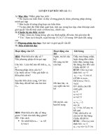
III. Fission yield
III. Fission yield
Fissions of uranium-235 nucleus can end up with 80
Fissions of uranium-235 nucleus can end up with 80
different primary fission products. The range of mass
different primary fission products. The range of mass
numbers of products is from 72 (isotope of zinc) to 161
numbers of products is from 72 (isotope of zinc) to 161
(possibly an isotope of terbium). The yields of the products
(possibly an isotope of terbium). The yields of the products
of thermal fission of uranium-233, uranium-235,
of thermal fission of uranium-233, uranium-235,
plutonium-239 and a mixture of uranium and plutonium are
plutonium-239 and a mixture of uranium and plutonium are
shown in following figure III.1.
shown in following figure III.1.
THERMAL-HYDRAULIC IN
NUCLEAR REACTOR
Figure III.1: Fission yield as a function of mass number of
Figure III.1: Fission yield as a function of mass number of
the fission product.
the fission product.
As can be seen in all cases there are two groups of fission
As can be seen in all cases there are two groups of fission
products: a “light” group with mass number between 80
products: a “light” group with mass number between 80
and 110 and a “heavy” group with mass numbers between
and 110 and a “heavy” group with mass numbers between
125 and 155.
125 and 155.
THERMAL-HYDRAULIC IN
NUCLEAR REACTOR
Figure III.2: Illustration of t
Figure III.2: Illustration of t
he 6 formula:
he 6 formula:
THERMAL-HYDRAULIC IN
NUCLEAR REACTOR
IV. Decay heat
IV. Decay heat
A large portion of the radioactive fission products emit
A large portion of the radioactive fission products emit
gamma rays, in addition to beta particles. The amount and
gamma rays, in addition to beta particles. The amount and
activity of individual fission products and the total fission
activity of individual fission products and the total fission
product inventory in the reactor fuel during operation and
product inventory in the reactor fuel during operation and
after shut-down are important for several reasons: namely
after shut-down are important for several reasons: namely
to evaluate the radiation hazard, and to determine the
to evaluate the radiation hazard, and to determine the
decrease of the fission product radioactivity in the spent
decrease of the fission product radioactivity in the spent
fuel elements after removal from the reactor. This
fuel elements after removal from the reactor. This
information is required to evaluate the length of the cooling
information is required to evaluate the length of the cooling
period before the fuel can be reprocessed.
period before the fuel can be reprocessed.
Right after the insertion of a large negative reactivity to the
Right after the insertion of a large negative reactivity to the
reactor core (for example, due to an injection of control
reactor core (for example, due to an injection of control
rods), the neutron flux rapidly decreases according to the
rods), the neutron flux rapidly decreases according to the
following equation,
following equation,
THERMAL-HYDRAULIC IN
NUCLEAR REACTOR
Φ(t) = Ф
Φ(t) = Ф
0
0
{(β / β – ρ) e
{(β / β – ρ) e
(λρ / β – ρ)t
(λρ / β – ρ)t
- (ρ / β – ρ))e
- (ρ / β – ρ))e
(β – ρ / l)t
(β – ρ / l)t
}
}
(IV.1)
(IV.1)
Here f (
Here f (
t
t
) is the neutron flux at time t after reactor shut-
) is the neutron flux at time t after reactor shut-
down, 0 f is the neutron flux during reactor operation at full
down, 0 f is the neutron flux during reactor operation at full
power, r is the step change of reactivity,
power, r is the step change of reactivity,
β
β
is the fraction of
is the fraction of
delayed neutrons, l is the prompt neutron lifetime and l is
delayed neutrons, l is the prompt neutron lifetime and l is
the mean decay constant of precursors of delayed neutrons.
the mean decay constant of precursors of delayed neutrons.
For LWR with uranium-235 as the fissile material, typical
For LWR with uranium-235 as the fissile material, typical
values are as follows: l = 0.08 s-1,
values are as follows: l = 0.08 s-1,
β
β
= 0.0065 and l = 10-
= 0.0065 and l = 10-
3s.
3s.
Assuming the negative step-change of reactivity r = -0.09,
Assuming the negative step-change of reactivity r = -0.09,
the relative neutron flux change is given as:
the relative neutron flux change is given as:
Ф(t) / Ф0 = 0.067 e
Ф(t) / Ф0 = 0.067 e
-0.075t
-0.075t
+ 0.933 e
+ 0.933 e
-96.5t
-96.5t
(IV-2
(IV-2
)
)
THERMAL-HYDRAULIC IN
NUCLEAR REACTOR
The second term in Eq. (4-3) is negligible already after t =
The second term in Eq. (4-3) is negligible already after t =
0.01s and only the first term has to be taken into account in
0.01s and only the first term has to be taken into account in
calculations. As can be seen, the neutron flux (and thus the
calculations. As can be seen, the neutron flux (and thus the
generated power) immediately jumps to ~6.7% of its initial
generated power) immediately jumps to ~6.7% of its initial
value and then it is reduced e-fold during period of time
value and then it is reduced e-fold during period of time
T
T
=
=
1/0.075 = 13.3 s.
1/0.075 = 13.3 s.
After a reactor is shut down and the neutron flux falls to
After a reactor is shut down and the neutron flux falls to
such a small value that it may be neglected, substantial
such a small value that it may be neglected, substantial
amounts of heat continue to be generated due to the beta
amounts of heat continue to be generated due to the beta
particles and the gamma rays emitted by the fission
particles and the gamma rays emitted by the fission
products. FIGURE 4-2 shows the fission product decay heat
products. FIGURE 4-2 shows the fission product decay heat
versus the time after shut down. The curve, which covers a
versus the time after shut down. The curve, which covers a
time range from 1 to 106 years after shut down, refers to a
time range from 1 to 106 years after shut down, refers to a
hypothetical pressurized water cooled reactor that has
hypothetical pressurized water cooled reactor that has
operated at a constant power for a period of time during
operated at a constant power for a period of time during
which the fuel (with initial enrichment 4.5%) has reached
which the fuel (with initial enrichment 4.5%) has reached
50 GWd/tU burn-up and is then shut down instantaneously.
50 GWd/tU burn-up and is then shut down instantaneously.
Contributions from various species which are present in the
Contributions from various species which are present in the
spent fuel are indicated.
spent fuel are indicated.
THERMAL-HYDRAULIC IN
NUCLEAR REACTOR
Figure IV.1: Fission product decay heat power (W/metric ton
Figure IV.1: Fission product decay heat power (W/metric ton
of HM) versus time after shutdown
of HM) versus time after shutdown
.
.
THERMAL-HYDRAULIC IN
NUCLEAR REACTOR
Figure IV.2: Relative decay power versus relative time after
Figure IV.2: Relative decay power versus relative time after
reactor shutdown for various operation periods from 1 month
reactor shutdown for various operation periods from 1 month
to 12 months.
to 12 months.
THERMAL-HYDRAULIC IN
NUCLEAR REACTOR
The power density change due to beta and gamma radiation
The power density change due to beta and gamma radiation
can be calculated from the fllowing approximate equation
can be calculated from the fllowing approximate equation
[IV-1],
[IV-1],
q” / q”
q” / q”
0
0
= 0.065 { t - t
= 0.065 { t - t
op
op
)
)
-0.2
-0.2
- t
- t
-0.2
-0.2
} (IV.3)
} (IV.3)
Here q”0 is the power density in the reactor at steady state
Here q”0 is the power density in the reactor at steady state
operation before shut down,
operation before shut down,
q
q
” is the decay power density,
” is the decay power density,
t
t
is the time after reactor shut down [s] and
is the time after reactor shut down [s] and
top
top
is the time
is the time
of reactor operation before shut down [s]. Equation (IV-3)
of reactor operation before shut down [s]. Equation (IV-3)
is applicable regardless of whether the fuel containing the
is applicable regardless of whether the fuel containing the
fission products remains in the reactor core or it is removed
fission products remains in the reactor core or it is removed
from it. However, the equation accuracy and applicability is
from it. However, the equation accuracy and applicability is
limited and can be used for cooling periods from
limited and can be used for cooling periods from
approximately 10 s to less than 100 days.
approximately 10 s to less than 100 days.
THERMAL-HYDRAULIC IN
NUCLEAR REACTOR
Equation (IV.3) can be transformed to:
Equation (IV.3) can be transformed to:
q”’ / q”
q”’ / q”
0
0
= 0.065 / t
= 0.065 / t
op
op
0.2
0.2
{ 1 / (t – t
{ 1 / (t – t
op
op
/ t
/ t
op
op
)
)
0.2
0.2
- 1 / (t / t
- 1 / (t / t
op
op
)
)
0.2
0.2
} (IV.4)
} (IV.4)
Here = (t – tʘ
Here = (t – tʘ
op
op
) / t
) / t
op
op
is the relative time after reactor
is the relative time after reactor
shut down. Equation (IV.4) is shown in FIGURE IV.2 for the
shut down. Equation (IV.4) is shown in FIGURE IV.2 for the
reactor operation time
reactor operation time
top
top
from 1 month to 1 year.
from 1 month to 1 year.
V. Spatial distribution of the heat sources
V. Spatial distribution of the heat sources
The energy released in nuclear fission reaction is
The energy released in nuclear fission reaction is
distributed among a variety of reaction products
distributed among a variety of reaction products
characterized by different range and time delays. Once
characterized by different range and time delays. Once
performing the thermal design of a reactor core, the energy
performing the thermal design of a reactor core, the energy
deposition distributed over the coolant and structural
deposition distributed over the coolant and structural
materials is frequently reassigned to the fuel in order to
materials is frequently reassigned to the fuel in order to
simplify the thermal analysis of the core. The volumetric
simplify the thermal analysis of the core. The volumetric
fission heat source in the core can be found in general case
fission heat source in the core can be found in general case
as:
as:
THERMAL-HYDRAULIC IN
NUCLEAR REACTOR
q”’ (r) = Σ
q”’ (r) = Σ
i
i
w
w
f
f
(i)
(i)
Ni (r) ƒ
Ni (r) ƒ
0
0
∞
∞
dEσ
dEσ
f
f
(
(
i)
i)
(E)Ф (r,E) (V.1)
(E)Ф (r,E) (V.1)
Here (
Here (
i
i
)
)
f w
f w
is the recoverable energy released per fission
is the recoverable energy released per fission
event of i-th fissile material, (r)
event of i-th fissile material, (r)
i N
i N
is the number density of
is the number density of
i-th fissile material at location r and (
i-th fissile material at location r and (
E
E
)
)
i
i
f
f
s is its microscopic fission cross section for neutrons with
s is its microscopic fission cross section for neutrons with
energy E. Since the neutron flux and the number density of
energy E. Since the neutron flux and the number density of
the fuel vary across the reactor core, there will be a
the fuel vary across the reactor core, there will be a
corresponding variation in the fission heat source.
corresponding variation in the fission heat source.
The simplest model of fission heat distribution would
The simplest model of fission heat distribution would
correspond to a bare,
correspond to a bare,
homogeneous core. One should recall here the one-group
homogeneous core. One should recall here the one-group
flux distribution for such geometry given as:
flux distribution for such geometry given as:
THERMAL-HYDRAULIC IN
NUCLEAR REACTOR
Ф(r, z) = Ф
Ф(r, z) = Ф
0
0
J
J
0
0
{2.405r / R}cos{πz / H} (V.2)
{2.405r / R}cos{πz / H} (V.2)
Here 0 is the flux at the center of the core and
Here 0 is the flux at the center of the core and
R
R
and
and
H
H
are
are
effective (extrapolated) core dimensions that include
effective (extrapolated) core dimensions that include
extrapolation lengths as well as an adjustment to account
extrapolation lengths as well as an adjustment to account
for a reflected core.
for a reflected core.
Having a fuel rod located at r = rf distance from the
Having a fuel rod located at r = rf distance from the
centerline of the core, the
centerline of the core, the
volumetric fission heat source becomes a function of the
volumetric fission heat source becomes a function of the
axial coordinate, z, only:
axial coordinate, z, only:
q”’(z) = wfΣfФ
q”’(z) = wfΣfФ
0
0
J
J
0
0
{2.405rf / R}cos{πz / H} (V.3)
{2.405rf / R}cos{πz / H} (V.3)
There are numerous factors that perturb the power
There are numerous factors that perturb the power
distribution of the reactor core, and the above equation will
distribution of the reactor core, and the above equation will
not be valid. For example fuel is usually not loaded with
not be valid. For example fuel is usually not loaded with
uniform enrichment. At the beginning of core life, higher
uniform enrichment. At the beginning of core life, higher
enrichment fuel is loaded toward the edge of the core in
enrichment fuel is loaded toward the edge of the core in
order to flatten the power distribution. Other factors
order to flatten the power distribution. Other factors
include the influence of the control rods and variation of the
include the influence of the control rods and variation of the
coolant density.
coolant density.
THERMAL-HYDRAULIC IN
NUCLEAR REACTOR
All these power perturbations will cause a corresponding
All these power perturbations will cause a corresponding
variation of temperature distribution in the core. A usual
variation of temperature distribution in the core. A usual
technique to take care of these variations is to estimate the
technique to take care of these variations is to estimate the
local working conditions (power level, coolant flow, etc)
local working conditions (power level, coolant flow, etc)
which are the closest to the thermal limitations. Such part
which are the closest to the thermal limitations. Such part
of the core is called hot channel and the working conditions
of the core is called hot channel and the working conditions
are related with so-called hot channel factors.
are related with so-called hot channel factors.
One common approach to define hot channel is to choose
One common approach to define hot channel is to choose
the channel where the core heat flux and the coolant
the channel where the core heat flux and the coolant
enthalpy rise is a maximum. Working conditions in the hot
enthalpy rise is a maximum. Working conditions in the hot
channel are defined by several ratios of local conditions to
channel are defined by several ratios of local conditions to
core-averaged conditions.
core-averaged conditions.
These ratios, termed the hot
These ratios, termed the hot
channel factors or power peaking factors will be considered
channel factors or power peaking factors will be considered
in more detail in coming Chapters. However, it can be
in more detail in coming Chapters. However, it can be
mentioned already
mentioned already
here that the basic initial plant
here that the basic initial plant
thermal design relay on these factors.
thermal design relay on these factors.