Nghiên cứu ứng xử của kết cấu chống trong đường hầm tiết diện hình chữ nhật cong chịu tải trọng động đất
Bạn đang xem bản rút gọn của tài liệu. Xem và tải ngay bản đầy đủ của tài liệu tại đây (6.66 MB, 125 trang )
MINISTRY OF EDUCATION AND TRAINING
HANOI UNIVERSITY OF MINING AND GEOLOGY
PHAM VAN VI
BEHAVIOR OF SUB-RECTANGULAR TUNNELS UNDER SEISMIC LOADING
PhD THESIS
HANOI, May 2022
BỘ GIÁO DỤC VÀ ĐÀO TẠO
TRƯỜNG ĐẠI HỌC MỎ - ĐỊA CHẤT
PHẠM VĂN VĨ
NGHIÊN CỨU ỨNG XỬ CỦA KẾT CẤU CHỐNG TRONG ĐƯỜNG HẦM
TIẾT DIỆN HÌNH CHỮ NHẬT CONG CHỊU TẢI TRỌNG ĐỘNG ĐẤT
LUẬN ÁN TIẾN SĨ KỸ THUẬT
HÀ NỘI - 05/2022
MINISTRY OF EDUCATION AND TRAINING
HA NOI UNIVERSITY OF MINING AND GEOLOGY
PHAM VAN VI
BEHAVIOR OF SUB-RECTANGULAR TUNNELS UNDER SEISMIC LOADING
Major: Underground construction engineering
Code: 9580204
PhD THESIS
SUPERVISORS:
1. Asso. Prof., Dr. Do Ngoc Anh
2. Prof., Dr. Dias Daniel
HA NOI, May 2022
BỘ GIÁO DỤC VÀ ĐÀO TẠO
TRƯỜNG ĐẠI HỌC MỎ - ĐỊA CHẤT
PHẠM VĂN VĨ
NGHIÊN CỨU ỨNG XỬ CỦA KẾT CẤU CHỐNG TRONG ĐƯỜNG HẦM TIẾT
DIỆN HÌNH CHỮ NHẬT CONG CHỊU TẢI TRỌNG ĐỘNG ĐẤT
Ngành đào tạo: Kỹ thuật Xây dựng Cơng trình ngầm
Mã số ngành: 9580204
LUẬN ÁN TIẾN SĨ KỸ THUẬT
NGƯỜI HƯỚNG DẪN KHOA HỌC:
1. PGS.TS Đỗ Ngọc Anh
2. GS.TS Dias Daniel
HÀ NỘI - 05/2022
i
ACKNOWLEDGEMENTS
The work described within this thesis was conducted at the Underground and
Mining Construction Department, Faculty of Civil Engineering, Hanoi University of
Mining and Geology, Vietnam.
First of all, I am particularly grateful to my supervisors, Associate Professor,
Dr. Do Ngoc Anh, and Professor Daniel Dias. They have enthusiastically supported
and directed me to provide invaluable advices in the process of preparing this thesis
and research articles. I would like to thank Associate Professor, Dr. Do Ngoc Anh for
his regular support from the very beginning to the completion of this thesis. He
pushed me to reach my full potential. His professional guidance and willingness to
work on an ongoing basis were key elements in completing this study. I would like
to thank Professor Daniel Dias for his invaluable guidance, supervision,
encouragement, and support throughout this research process. I would like to record
my sincere appreciation for their help and I will never forget my three years of Ph.D.
studies under their guidance, my respected teachers.
Second, I also want to thank the teachers and staff of the Underground and
Mining Construction Department, Faculty of Construction, Postgraduate training
Office, Hanoi University of Mining and Geology, who helped me in the process of
implementing this thesis.
Third, I would like to thank the Vingroup JSC and supported by the Master, PhD
Scholarship Programme of Vingroup Innovation Foundation (VINIF), Institute of Big
Data, code VINIF.2021.TS.167 for financial support. This is an honor and a great
motivation that helped me to make this research more focused.
Finally, I am deeply grateful to my family for their support, patience, and love.
This study would not have been started, would not have been possible, and would
never have been completed without the support of my wife, Vu Thi Hue, and my two
children, Khanh An and Minh Tri. Nothing would have happened without their
support and I devoted them to this thesis.
ii
LỜI CẢM ƠN
Luận án này được thực hiện tại Bộ mơn Xây dựng cơng trình ngầm và Mỏ, Khoa
Xây dựng, Trường Đại học Mỏ - Địa chất
Đầu tiên, tác giả xin đặc biệt cảm ơn tới tổ hướng dẫn, PGS.TS Đỗ Ngọc Anh
và GS Daniel Dias. Các Thầy luôn định hướng, khuyến khích, thúc đẩy NCS và có
những lời khun quý báu, chân thành giúp cho tác giả trong quá trình thực hiện luận
án cũng như viết các bài báo khoa học.
Thứ hai, tác giả muốn cảm ơn tới các Thầy cơ Bộ mơn Xây dựng cơng trình
ngầm và mỏ, Khoa Xây dựng, Phòng Đào tạo Sau đại học Trường Đại học Mỏ - Địa
chất đã luôn giúp đỡ, tạo điều kiện cho tác giả trong quá trình thực hiện luận án này.
Thứ ba, tác giả muốn cảm ơn tới Tập đồn Vingroup và sự hỗ trợ của Chương
trình học bổng thạc sĩ, tiến sĩ trong nước của Quỹ Đổi mới sáng tạo Vingroup
(VINIF), Viện Nghiên cứu Dữ liệu lớn, mã số VINIF.2021.TS.167 đã tài trợ. Đây là
một vinh dự và là động lực lớn giúp tác giả tập trung hơn trong nghiên cứu khoa học.
Cuối cùng, tác giả vô cùng biết ơn tới gia đình đã ln bên cạnh với sự kiên
nhẫn. Luận án này sẽ không được bắt đầu, được thực hiện và hồn thành nếu khơng
có sự hỗ trợ của gia đình.
iii
GUARANTEE
I hereby declare that this is my own research work. The data and results
presented in this thesis are honest and have never been published in any other
works.
PhD candidate
Pham Van Vi
iv
LỜI CAM ĐOAN
Tơi xin cam đoan đây là cơng trình nghiên cứu của riêng tôi. Các kết quả và dữ
liệu trong luận án là trung thực và chưa từng được cơng bố trong bất kỳ cơng trình
nào.
Nghiên cứu sinh
Phạm Văn Vĩ
v
SUMMARY
The principal purpose of this Ph.D. thesis is to study the behavior of subrectangular tunnels under seismic conditions by using a finite difference method
(FDM) and then a new quasi-static loading scheme, applied to the Hyperstatic
Reaction Method (HRM), was developed.
Firstly, a literature review on the tunnel lining design under seismic condition
was conducted. Secondly, 2D numerical models of circular and sub-rectangular
tunnels subjected to quasi-static loading were developed. The difference in behavior
of these two tunnel types under seismic loading was highlighted. In the final part of
the manuscript, a new quasi-static loading scheme applied in sub-rectangular tunnels
using the HRM method was proposed based on the quasi-static loading principle. Its
reliability is demonstrated based on validations conducted by using finite difference
caculations considering different situations.
Keywords: Sub-rectangular tunnel; Hyperstatic Reaction Method; Numerical
model; Quasi-static.
vi
TĨM TẮT
Mục tiêu chính của luận án là sử dụng phương pháp số sai phân hữu hạn (FDM)
để nghiên cứu ứng xử của đường hầm tiết diện hình chữ nhật cong chịu tải trọng động
đất và phát triển một sơ đồ tải trọng tĩnh tương đương mới áp dụng trong phương
pháp lực kháng đàn hồi (HRM).
Trên cơ sở kết quả nghiên cứu tổng quan chỉ ra khoảng trống nghiên cứu đối
với kết cấu đường hầm tiết diện chữ nhật cong chịu tải trọng động đất, luận án đã
phát triển mô hình số 2D cho đường hầm tiết diện hình chữ nhật cong chịu tải trọng
tĩnh tương đương trên cơ sở mơ hình của đường hầm tiết diện hình trịn được kiểm
chứng bằng cách so sánh với phương pháp giải tích. Ứng xử khác nhau của kết cấu
chống trong hai loại tiết diện đường hầm khi chịu tải trọng động đất đã được chỉ ra.
Dựa vào kết quả phân tích trên mơ hình số FDM, luận án đã đề xuất được một sơ đồ
tải trọng tĩnh tương đương mới tác dụng lên kết cấu chống đường hầm tiết diện hình
chữ nhật cong chịu tải trọng động đất trong phương pháp HRM. Độ tin cậy của sơ đồ
tải trọng tĩnh tương đương mới đã được kiểm chứng trên cơ sở so sánh với phương
pháp FDM khi xem xét một loạt điều kiện đầu vào khác nhau.
Từ khóa: Đường hầm tiết diện chữ nhật cong; Phương pháp lực kháng đàn hồi;
Mơ hình số; Tĩnh tương đương.
vii
CONTENTS
ACKNOWLEDGEMENTS ....................................................................................... i
SUMMARY ............................................................................................................... v
LIST OF NOMENCLATURE ................................................................................ ix
LIST OF FIGURES ................................................................................................xii
LIST OF TABLES .................................................................................................. xv
GENERAL INTRODUCTION ............................................................................. xvi
Background and Problematic ................................................................................xvi
Objectives ........................................................................................................... xvii
Scope of this study ............................................................................................. xviii
Original Features................................................................................................ xviii
Thesis outline ..................................................................................................... xviii
CHAPTER 1: LITERATURE REVIEW ON THE BEHAVIOUR OF
UNDERGROUND STRUCTURES UNDER SEISMIC LOADING ................... 1
1.1. Introduction .......................................................................................................1
1.2. Seismic response mechanisms .......................................................................... 3
1.3. Research methods ............................................................................................. 7
1.3.1. Analytical solutions ....................................................................................8
1.3.2. Physical tests ............................................................................................16
1.3.3. Numerical modeling ................................................................................. 20
1.4. Sub-rectangular tunnels .................................................................................25
1.5. Conclusions ..................................................................................................... 27
CHAPTER 2: NUMERICAL STUDY ON THE BEHAVIOR OF SUBRECTANGULAR TUNNEL UNDER SEISMIC LOADING ............................ 29
2.1. Numerical simulation of the circular tunnel under seismic loading ...............30
2.1.1. Reference case study- Shanghai metro tunnel..........................................30
2.1.2. Numerical model for the circular tunnel ..................................................31
2.1.3. Comparison of the numerical and analytical model for the circular tunnel
case study............................................................................................................ 34
2.2. Validation of circular tunnel under seismic loading .......................................37
viii
2.2.1. Effect of the peak horizontal seismic acceleration (aH) ...........................38
2.2.2. Effect of the soil Young’s modulus, Es ....................................................39
2.2.3. Effect of the lining thickness, t................................................................. 40
2.3. Numerical simulation of the sub-rectangular tunnel under seismic loading ..42
2.4. Parametric study of sub-rectangular tunnels in quasi-static conditions .........42
2.4.1. Effect of the peak horizontal seismic acceleration (aH) ...........................44
2.4.2. Effect of the soil’s Young’s modulus (Es)................................................46
2.4.3. Effect of the lining thickness (t) ............................................................... 47
2.5. Conclusion ...................................................................................................... 48
CHAPTER 3: A NEW QUASI-STATIC LOADING SCHEME FOR THE
HYPERSTATIC REACTION METHOD - CASE OF SUB-RECTANGULAR
TUNNELS UNDER SEISMIC CONDITION ...................................................... 51
3.1. Fundamental of HRM method applied to sub-rectangular tunnel under static
loading ................................................................................................................... 52
3.2. HRM method applied to sub-rectangular tunnel under seismic conditions ...57
3.3. Numerical implementation ............................................................................. 61
3.3.1. FDM numerical model ............................................................................. 61
3.3.2. Numerical procedure in HRM method .....................................................63
3.4. Validation of the HRM method ...................................................................... 69
3.4.1. Validation 1 ..............................................................................................70
3.4.2 Validation 2 ...............................................................................................71
3.4.3 Validation 3 ...............................................................................................72
3.4.4. Validation 4 ..............................................................................................73
3.4.5. Validation 5 ..............................................................................................74
3.4.6. Validation 6 ..............................................................................................75
3.4.7. Validation 7 ..............................................................................................76
3.5. Conclusions ..................................................................................................... 77
GENERAL CONCLUSIONS AND PERSPECTIVES ........................................ 79
PUBLISHED AND SUBMITTED MANUSCRIPTS........................................... 83
REFERENCES ........................................................................................................ 84
ix
LIST OF NOMENCLATURE
Abbreviations
2D
Two-dimensional
3D
Three-dimensional
DOT
Double-O-tube
FDM
Finite difference method
FEM
Finite element method
fs
Full slip
HRM
Hyperstatic Reaction Method
MF
Multi-circular face
ns
No-slip
PGA
Peak ground acceleration
PIV
Particle image velocimetry
SR
Sub-rectangular tunnel
TBM
Tunnel boring machine
Symbols
aH
Peak horizontal acceleration at the ground surface
a, b, β
Dimensionless factors
C
Tunnel lining compressibility ratio
c
Soil cohesion
D
Circular tunnel external diameter
E
Young’s modulus of the tunnel lining
Es
Young’s modulus of the ground
F
Tunnel lining flexibility ratio
G
Soil shear modulus
x
Gmax
Maximum ground shear modulus
h
Tunnel height
H
Tunnel depth
I
Inertia moment of tunnel lining per unit length of the tunnel
K
Soil bulk modulus
K0
Lateral earth pressure coefficient
K1
Full slip lining response coefficient
K2
No-slip lining response coefficient
K3
No-slip lining response coefficient
K4
No-slip lining response coefficient
Li
Element length
M
Incremental Bending moment
Mmax
Maximum incremental bending moment
Mmin
Minimum incremental bending moment
Mw
Moment magnitude
N
Incremental Normal forces
Nmax
Maximum incremental normal forces
Nmin
Minimum incremental normal forces
plim
Maximum reaction pressure
R
Tunnel radius
Ri
Radius of part i (i=1, 2 and 3 corresponding to the crown, shoulder
and sidewall) of the tunnel boundary
t
Tunnel lining thickness
u
Axial displacement
v
Transversal displacement
Vmax
Peak shear wave velocity
xi
Vs
The ground shear wave velocity
w
Tunnel width
∆zmin
Smallest dimension in the normal direction of zones
γ
Soil unit weight
γmax
Maximum shear strain
ηn,0
Soil initial stiffness
θ
Angle measured counter-clockwise from spring line on the right
λi
Transformation matrix
ν
Tunnel lining Poisson’s ratio
νs
Soil Poisson’s ratio
ρmax
Soil density
τ
Shear stresses applied at the far-field boundary
φ
Soil internal friction angle
𝜂
Soil initial spring stiffness
𝜂
Normal stiffness
𝜂
Tangential stiffness
𝜎
Vertical loads
𝜎
Horizontal loads
[K]
Stiffness matrix
[S]
Nodal displacement matrix
[F]
Nodal forces matrix
xii
LIST OF FIGURES
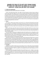
Figure 1.1. Summary of observed bored/mined tunnel damage due to ground shakings
[131]. ........................................................................................................................... 2
Figure 1.2. Typical failure modes of mountain tunnels reported during the 1999 ChiChi earthquake in Taiwan [160]. ................................................................................. 3
Figure 1.3. Ground response to seismic waves [159] ................................................. 4
Figure 1.4. Type of tunnel deformations during a seismic event [123] ...................... 5
Figure 1.5. Examples of the effects of seismically-induced ground failures on tunnels
[155]. ........................................................................................................................... 6
Figure 1.6. A circular tunnel (redrawn) [126] ............................................................. 9
Figure 1.7. Seismic shear loading and equivalent static loading (redrawn) [126] .... 10
Figure 1.8. Definition of terms used in racking analysis of a rectangular tunnel [159].
................................................................................................................................... 14
Figure 1.9. Racking coefficients for rectangular tunnels [59]. ................................. 16
Figure 1.10. Geometry and boundary conditions in the quasi-static model [135] .... 21
Figure 1.11 Geometry and boundary conditions in the quasi-static model [49] ....... 22
Figure 1.12. (a) 2D and (b) 3D numerical model in ABAQUS [150] ...................... 23
Figure 1.13. (a) Acceleration time history scaled at 0.35g (b) The corresponding
Fourier spectrum [12] ................................................................................................ 23
Figure 1.14. (a) Overlap cutter heads; (b) a copy cutter head [78] ........................... 25
Figure 1.15. A photo showing the testing setup after fabrication [72] ..................... 26
Figure 2.1. Sub-rectangular express tunnel in Shanghai [48], distances in millimeters
................................................................................................................................... 30
Figure 2.2. Circular tunnel with the same utilization space area, distances in
millimeters................................................................................................................. 31
Figure 2.3. The plane strain model under consideration ........................................... 32
Figure 2.4. Geometry and quasi-static loading conditions for the circular tunnel model
................................................................................................................................... 33
Figure 2.5. Deformed model and displacement contours in circular tunnel model for
no-slip condition........................................................................................................ 36
xiii
Figure 2.6. Deformed model and displacement contours in circular tunnel model for
full-slip condition ...................................................................................................... 36
Figure 2.7. Distribution of the incremental internal forces in the circular tunnel by
Flac3D and Wang solution. ....................................................................................... 37
Figure 2.8. Effect of aH on the extreme incremental internal forces of the circular
tunnel lining .............................................................................................................. 38
Figure 2.9. Effect of Es on the incremental internal forces of the circular tunnel lining
................................................................................................................................... 40
Figure 2.10. Effect of the lining thickness on the incremental internal forces in the
circular tunnel lining ................................................................................................. 41
Figure 2.11. Geometry and quasi-static loading conditions in the numerical model of
a sub-rectangular tunnel ............................................................................................ 42
Figure 2.12. Deformed model and displacement contours in Sub-rectangular tunnel
model for no-slip condition ....................................................................................... 43
Figure 2.13. Deformed model and displacement contours in Sub-rectangular tunnel
model for full-slip condition ..................................................................................... 43
Figure 2.14. Distribution of the incremental bending moments and normal forces in
the sub-rectangular tunnel ......................................................................................... 44
Figure 2.15. Effect of the aH value on the internal forces of circular and subrectangular tunnel linings .......................................................................................... 45
Figure 2.16. Effect of the Es value on the internal forces for the circular and subrectangular tunnel linings .......................................................................................... 46
Figure 2.17. Effect of the lining thickness on the incremental internal forces of the
circular and sub-rectangular tunnel linings ............................................................... 48
Figure 3.1. Calculation scheme of support structures with the HRM method under
static conditions. With σv: the vertical loads; σh: the horizontal loads; kn: normal
stiffness of springs; ks: shear stiffness of spring; EI and EA: bending and normal
stiffness of the support; X and Y are the global Cartesian coordinates [48] ............ 52
Figure 3.2. A finite element under the local Cartesian coordinates: i: initial node; i+1:
final node; θ: rotation; x and y: local Cartesian coordinates; ν: transversal
displacement; u: axial displacement; Li: element length [120]. ................................ 53
Figure 3.3. Nonlinear relationship between the reaction pressure p and the support normal
displacement δ: η0: initial spring stiffness; plim: maximum reaction pressure [121]. ............ 55
xiv
Figure 3.4. Transversal response in 2D plane strain conditions of the circular tunnel
(a) ovaling deformation; (b) corresponding seismic shear loading; (c) sub-ovaling
deformation; (d) corresponding seismic shear loading. ............................................ 58
Figure 3.5. Incremental bending moments and normal forces of sub-rectangular
tunnel obtained using FDM model............................................................................ 60
Figure 3.6. Equivalent static loading with the HRM method for sub-rectangular
tunnel. ........................................................................................................................ 60
Figure 3.7. Shapes of tunnel cases (unit: m) [48] ..................................................... 63
Figure 3.8. Calibration flowchart of the three parameters ........................................ 65
Figure 3.9. Obtained numerical results and fitting curves adopted for the parameters
β1, β2, β3 and β4 that created the parameter β. ........................................................... 67
Figure 3.10. Coefficients fitting curves for the formulas of the parameters a and b1,
b2, b3 and b4 that created the parameter b ............................................................... 68
Figure 3.11. Comparison of the incremental bending moments and normal forces
calculated by the developed HRM method and numerical FDM calculation ........... 69
Figure 3.12. Horizontal accelerations aH impact on extreme incremental internal
forces of the sub-rectangular tunnel lining ............................................................... 70
Figure 3.13. Effect of Es on the extreme incremental internal forces of the subrectangular tunnel lining ........................................................................................... 71
Figure 3.14. Effect of the lining thickness on the extreme incremental internal forces
of the sub-rectangular tunnel lining .......................................................................... 72
Figure 3.15. The cross-section dimensions influence on the extreme incremental
internal forces of the sub-rectangular tunnel lining .................................................. 73
Figure 3.16. Effect of the shape of cross-section on the extreme incremental internal
forces of the sub-rectangular tunnel lining ............................................................... 75
Figure 3.17. Effect of burial depth of tunnel on the extreme incremental internal
forces of the sub-rectangular tunnel lining ............................................................... 76
xv
LIST OF TABLES
Table 1.1. Ratios of ground motion at depth to motion at ground surface (after Power
et al. [130]) ............................................................................................................... 10
Table 1.2. Ratios of peak ground velocity to peak ground acceleration at surface in
rock and soil (adapted from Sadigh and Egan [134]) .............................................. 11
Table 1.3. Summary of researches on the tunnel subjected to seismic loading
classified by tunnel shapes and analyzing method.................................................... 24
Table 2.1. Input parameters for the reference case of seismic loading .................... 35
Table 3.1. Input parameters for the reference case for developing the HRM method
................................................................................................................................... 62
Table 3.2. Geometrical parameters of tunnel shape cases [48] ............................... 62
Table 3.3. Overview of the calibration process. ....................................................... 64
Table 3.4. Soil properties [70],[145] ........................................................................ 77
Table 3.5. Comparison of the results of the HRM method and FDM model ............ 77
xvi
GENERAL INTRODUCTION
Background and Problematic
Tunnels are an important component of the transportation and utility systems of
cities. They are being constructed at an increasing rate to facilitate the need for space
expansion in densely populated urban areas and mega-cities. Due to the interaction
of these structures with the surrounding soil and rock, underground structures are
more resistant to earthquakes than structures at the ground surface. Despite this, the
failure of underground structures was recorded for some earthquakes which occurred
around the world and damages reports were reported. Considering the substantial
scale and construction cost, and their critical role, this kind of infrastructures play in
modern society an important role. Even slight seismic loading impacts can lead to
short-time shutdowns and to substantial direct and indirect damages. Therefore, it is
very important to carefully consider the seismic loading effect on the design,
construction, operation, and risk assessment of tunnels.
The behavior of underground structures under seismic loading was often studied
by different methods, including analytical methods, empirical methods, and
numerical methods. It should be noted that most of the researches were conducted
considering circular or rectangular tunnels. There are many other types of tunnel
cross-sections, among them sub-rectangular tunnels were recently developed and are
the object of this thesis.
Advances in the development of user-friendly computer technology and the
limitations of analytical methods have led to an increase of the numerical methods
use for the design of tunnel linings. The numerical models could be finite element or
finite difference methods built by using in-house software or commercial software
packages. They allow to consider the complex interaction between the tunnel lining
and the surrounding ground and elements of the tunneling process.
Recently, the Hyperstatic Reaction Method (HRM), which is a finite element
method, was used to compute the internal forces developed in tunnel linings. This
xvii
method requires estimating the active loads of the soil mass applied directly on the
tunnel lining. The passive loads are induced by the soil reaction when the tunnel
lining moves toward the soil medium. The HRM method allows performing the
calculations in a very short time with a good accuracy. It is thus appropriate for
optimization design processes. The HRM method was successfully applied to design
circular, noncircular tunnels (e.g., U-shaped tunnel) under both static and seismic
loadings. Recently, it was also developed to estimate the behaviour of sub-rectangular
tunnels under static conditions.
This research aims to develop numerical methods used to calculate incremental
internal forces arising in sub-rectangular tunnel lining under seismic conditions. An
investigation of other parameters (tunnel lining, soil mass, etc.) influencing the tunnel
structure behavior subjected to seismic loadings is also proposed.
Objectives
The present thesis focuses on introducing a numerical analysis of subrectangular tunnels under seismic loading. Firstly, numerical models of subrectangular tunnels are developed based on numerical analyses of circular tunnels.
They are validated by comparison with well-known analytical solutions. Secondly,
the thesis focuses on developing the Hyperstatic Reaction Method (HRM) for subrectangular tunnels under seismic conditions. The main objectives of this thesis
include the following:
Highlighting the behavior of sub-rectangular tunnels subjected to seismic
loadings. A special attention is paid to the soil-lining interface conditions
Investigating the influence of parameters, like soil Young’s modulus,
maximum horizontal accelerations, and lining thickness on the subrectangular tunnel behavior under seismic loadings
Providing a new quasi-static loading scheme applied in the Hyperstatic
Reaction Method (HRM) for sub-rectangular tunnels under seismic loading
xviii
Scope of this study
Object of this study: Sub-rectangular tunnels supported by continuous lining.
The soil and tunnel lining material properties are assumed to be linearly
elastic.
Scope of this study: Calculate incremental internal forces arising in subrectangular tunnel lining under the seismic loading as well as investigation
of the parameters (tunnel lining, soil mass, etc.) influencing the behavior of
sub-rectangular tunnel structure subjected to seismic loadings.
Original Features
For the best of the author’s knowledge, the originality features of the present
work are:
Behavior of sub-rectangular tunnels subjected to seismic loadings.
Proposition of a new quasi-static loading scheme using the HRM method for
sub-rectangular tunnels under seismic loading.
Thesis outline
This thesis consists of 3 chapters. After introducing the issue to be considered,
Chapter 1 includes the review, analysis, and synthesis of scientific studies on
underground structures subjected to seismic loadings. The methods used to study the
internal forces appearing in the tunnel lining under seismic loading are presented.
Finally, sub-rectangular tunnels which were recently developed and studied are
introduced.
Chapter 2 focuses on introducing a numerical analysis of sub-rectangular tunnels
under seismic loadings. The numerical model of the sub-rectangular tunnel is based
on the numerical analyses of circular tunnels. They were validated by comparison
with well-known analytical solutions. This chapter aimed highlighting the differences
between the sub-rectangular tunnels behavior compared with circular ones, subjected
xix
to seismic loadings. A special attention is paid to the soil-lining interface, i.e., full
slip and no-slip conditions. The influence of parameters, like soil Young’s modulus,
maximum horizontal acceleration, and lining thickness of the sub-rectangular tunnels
under seismic loadings are also investigated. The results indicated a significant
difference in the sub-rectangular tunnel behavior in comparison with the circular
tunnel one when subjected to seismic loadings.
Chapter 3 aims providing a new quasi-static loading scheme applied in the HRM
method used for sub-rectangular tunnels under seismic conditions. New equations
allowing computations of the applied active loading as well as a varying spring
stiffness coefficient for representing the soil-tunnel lining interaction are introduced.
The proposed equations are calibrated and validated through a numerical analysis
considering a wide range of seismic magnitudes, soil properties, lining thicknesses,
tunnel dimensions, tunnel geometries and burial tunnel depths. The comparisons
show that the developed HRM method can be effectively used for the preliminary
seismic design of sub-rectangular tunnels.
1
CHAPTER 1
LITERATURE REVIEW ON THE BEHAVIOUR OF
UNDERGROUND STRUCTURES UNDER SEISMIC LOADING
1.1. Introduction
Tunnels are an important component of the transportation and utility systems in
urban and national systems. They were being constructed at an increasing rate to
facilitate the space expansion need in densely populated urban areas. Considering
their substantial scale and cost of construction, and their critical role, this kind of
infrastructures play an important role in modern societies. Even slight seismic loading
impacts can lead to short-time shutdowns and substantial direct and indirect damages.
Therefore, it is very important to carefully consider the effect of seismic loading on
the analysis, design, construction, operation, and risk assessment of tunnels.
As tunnels are interacting with the surrounding soil and/or rock environment,
they are more resistant to earthquakes than structures at the ground surface. The
destruction of underground constructions has recorded for many earthquakes taking
place around the world (e.g., Kobe, Japan 1995; Chi Chi, Taiwan 1999; Bolu, Turkey
Period 1999; Baladeh, Iran 2004; and more recently Sichuan, China in 2008). Reports
of damages [50],[158],[167] show that the effects interacting between the ground and
tunnels were not conducted a systematic investigation. In 1993, Wang highlighted the
notion of relative flexibility as a key parameter for understanding the seismic-induced
distortions of underground structures interacting with the surrounding ground.
Considering these incidents, it is clear that an improper designed underground
structures are susceptible to wave propagation effects [14],[15],[16],[74],[75],[111],
[166] (see Figure 1.1), Other detailed reviews of the seismic performance of tunnels
and
underground
structures
can
be
found
in
relevant
publications
[61],[69],[77],[94],[133],[168] (see Figure 1.2). These incidents were used as largescale 'standard cases', to understand the interplay between structure and ground, with
2
the ultimate goal of verifying the capabilities of design methods. Existing analysis
and validation of material models involved [81],[89] or interface conditions
[74],[90],[135] needed to capture the observed response. It was shown that there is
still a need to improve the quality of the design and computation of underground
structures in the areas that can suffer from earthquakes.
Figure 1.1. Summary of observed bored/mined tunnel damage due to ground
shakings [131].
Vietnam's territory is in a rather special position on the Earth's crust tectonic
map and it exists a complex, diverse, and high-risk network of earthquakes. There are
studies of earthquakes such as statistics, localization, forecasting, assessment of the
risk of earthquakes, and design [1],[2],[3],[4],[5],[6],[7],[8],[117],[118].