Advanced Computer Architecture - Lecture 8: Computer hardware design
Bạn đang xem bản rút gọn của tài liệu. Xem và tải ngay bản đầy đủ của tài liệu tại đây (1.39 MB, 43 trang )
CS 704
Advanced Computer Architecture
Lecture 8
Computer Hardware Design
(Multi Cycle Datapath and Control Design)
Prof. Dr. M. Ashraf Chughtai
Today’s Topics
Recap: Single cycle datapath and control
Example of Single Cycle Design
Multi Cycle Design - Datapath
Summary
MAC/VU-Advanced
Computer Architecture
Lecture 8 – Computer H/W Design (2)
2
Recap: Lecture 7
Basic building blocks of a computer:
CPU, Memory and I/O sub-systems and Buses
CPU sub-system: Datapath and control
Phases of instruction performing: Fetch and Execute
Datapath Designs: Uni-, 2- and 3-bus structures
Micro-operations of Fetch and execute phases:
- Fetch: MBR M[PC]; PC PC+4; IR MBR
- Exe: ID, operand read; exe; mem; WB
3-bus based single cycles data path – MIPS datapath
Control signals for single cycles data path – Add Instruction
MAC/VU-Advanced
Computer Architecture
Lecture 8 – Computer H/W Design (2)
3
A critical review of single cycle datapath and
control signals
Fetch Circuit
Instruction
Memory Address
nPC_sel
4
00
Adder
imm16
PC
Mux
Adder
PC Ext
MAC/VU-Advanced
Computer Architecture
Instruction<31:0>
Clk
address alignment at
the boundary of 4
Lecture 8 – Computer H/W Design (2)
4
A critical review of single cycle datapath and
control signals … Cont’d
5
Rt
busA
32
0
1
32
Zero
Rd
MemWr
Clk
Imm16
MemtoReg
0
32
Data In 32
ALUSrc
Rs
WrEn Adr
32
Mux
16
Extender
imm16
ALUctr
ALU
Rw Ra Rb
32 32bit
Registers
busB
32
Rt
<0:15>
5
Rs
Mux
32
Clk
5
Clk
<11:15>
1 Mux 0
RegWr
busW
Rt
<16:20>
RegDst
Rd
Instruction
Fetch Unit
<21:25>
nPC_sel
Instruction<31:0>
1
Data
Memory
ExtOp
MAC/VU-Advanced
Computer Architecture
Lecture 8 – Computer H/W Design (2)
5
Control Signals for Add rd,rs,rt
R[rd] R[rs] + R[rt]
RegWr = 1
5
16
Extender
imm16
32
1
Rs
Rd
Imm16
MemtoReg = 0
Zero MemWr = 0
0
32
Data In 32
Clk
WrEn Adr
32
Mux
busA
Rw Ra Rb
32
32 32bit
Registers
busB
0
32
Rt
Mux
32
Clk
5
ALUctr = Add
Rt
ALU
busW
5
Rs
<0:15>
1 Mux 0
Clk
<11:15>
Rt
<16:20>
Rd
Instruction
Fetch Unit
<21:25>
RegDst = 1
nPC_sel= +4
Instruction<31:0>
1
Data
Memory
ALUSrc = 0
MAC/VU-Advanced
Computer Architecture
ExtOp = x
Lecture 8 – Computer H/W Design (2)
6
Instruction Fetch Unit at the End of Add
PC <- PC + 4; This is the same for all instructions except: Branch and
Jump
Inst
Memory
Instruction<31:0>
Adr
nPC_sel
4
00
Adder
imm16
PC
Mux
Adder
MAC/VU-Advanced
Computer Architecture
Clk
Lecture 8 – Computer H/W Design (2)
7
The Single Cycle Datapath during Or Immediate
R[rt] <- R[rs] or ZeroExt[Imm16] 31
26
op
RegDst = 0
Rd
5
Rs
5
Rt
immediate
ALUctr = Or
MemtoReg = 0
Zero
16
Extender
imm16
32
1
0
32
Data In 32
ALUSrc = 1
MemWr = 0
Clk
ExtOp = 0
Lecture 8 – Computer H/W Design (2)
WrEn Adr
32
Mux
busA
Rw Ra Rb
32
32 32bit
Registers
busB
0
32
MAC/VU-Advanced
Computer Architecture
0
rt
Mux
32
Clk
rs
ALU
busW
16
Rt
1 Mux 0
RegWr = 1 5
21
1
Data
Memory
8
The Single Cycle Datapath during OR Immediate
Now let’s look at the control signals
setting for the OR immediate instruction.
The OR immediate instruction OR the
content of the register specified by the
Rs field to the Zero Extended Immediate
field and write the result to the register
specified in Rt.
This is how it works in the datapath. The
Rs field is fed to the Ra address port to
cause the contents of register Rs to be
placed on busA.
MAC/VU-Advanced
Computer Architecture
Lecture 8 – Computer H/W Design (2)
9
The Single Cycle Datapath during Or Immediate
T he other operand for the ALU will come
from the immediate field.
In order to do this, the controller need to set
ExtOp to 0 to instruct the extender to perform a
Zero Extend operation.
ALUSrc must set to 1 such that the MUX will
block off bus B from the register file and send
the zero extended version of the immediate
field to the ALU.
The ALUctr has to be set to OR so the ALU can
perform an OR operation.
MAC/VU-Advanced
Computer Architecture
Lecture 8 – Computer H/W Design (2)
10
The Single Cycle Datapath during Or Immediate
The rest of the control signals (MemWr,
MemtoReg, Branch, and Jump) are the same as the
Add and Subtract instructions.
One big difference is the RegDst signal. In this
case, the destination register is specified by
the instruction’s Rt field, NOT the Rd field
because we do not have a Rd field in the
instruction word
Consequently, RegDst must be set to 0 to place
Rt onto the Register File’s Rw address port.
Finally, in order to accomplish the register
write, RegWr must be set to 1.
MAC/VU-Advanced
Computer Architecture
Lecture 8 – Computer H/W Design (2)
11
The Single Cycle Datapath during Load
R[rt] <- Data Memory {R[rs] + SignExt[imm16]}
31
26
op
21
rs
ALUctr
= Add
Rt
busA
Rw Ra Rb
32
32 32bit
Registers
busB
0
32
Rt
Zero
32
Data In 32
ALUSrc = 1
MAC/VU-Advanced
Computer Architecture
ExtOp = 1
Rd
Imm16
MemtoReg = 1
MemWr = 0
0
Clk
Lecture 8 – Computer H/W Design (2)
Mux
16
Extender
imm16
1
Rs
32
Mux
32
Clk
5
Instruction
Fetch Unit
ALU
busW
5
Instruction<31:0>
<0:15>
RegWr = 1 5
Rs
immediate
<11:15>
1 Mux 0
Clk
rt
<16:20>
RegDst = 0
Rt
0
<21:25>
nPC_sel= +4
Rd
16
1
WrEn Adr
Data
Memory
32
12
The Single Cycle Datapath during Load
Let’s continue our lecture with the load
instruction. What does the load
instruction do?
It first adds the contents of the register
specified by the Rs field to the Sign
Extended version of the Immediate field to
form the memory address.
Then it uses this memory address to
access the memory and write the data
back to the register specified by the Rt
field of the instruction.
MAC/VU-Advanced
Computer Architecture
Lecture 8 – Computer H/W Design (2)
13
The Single Cycle Datapath during Load
Here is how the datapath works?
First the Rs field is fed to the Register File’s Ra
address port, to place the register onto bus A.
T hen the ExtOp signal is set to 1 so that the
immediate field is Sign Extended and we place
this value (output of Extender) onto the ALU
input by setting ALUsrc to 1.
The ALU then adds (ALUctr = add) the two
together to form the memory address which is
then placed onto the Data Memory’s address
port.
MAC/VU-Advanced
Computer Architecture
Lecture 8 – Computer H/W Design (2)
14
The Single Cycle Datapath during Load
In order to place the Data Memory’s output bus
onto the Register File’s input bus (busW), the
control needs to set MemtoReg to 1.
Similar to the OR immediate instruction, I showed
you earlier, the destination register here is
specified by the Rt field. Therefore RegDst must
be
set to 0.
Finally, RegWr must be set to 1 to completer the
register write operation.
Well, it should be obvious to you guys by now
that we need to set Branch and Jump to 0 to
make sure the Instruction Fetch Unit update the
Program Counter correctly.
MAC/VU-Advanced
Computer Architecture
Lecture 8 – Computer H/W Design (2)
15
The Single Cycle Datapath during Store
31
26
21
op
16
rs
0
rt
immediate
Data Memory {R[rs] + SignExt[imm16]} <- R[rt]
Instruction<31:0>
RegWr =
5
5
Rs
5
Rt
busA
32
0
1
MAC/VU-Advanced
Computer Architecture
ExtOp =
Rd
MemWr =
Clk
Lecture 8 – Computer H/W Design (2)
Imm16
MemtoReg =
0
32
Data In 32
ALUSrc =
Rs
WrEn Adr
32
Mux
16
Extender
imm16
32
Mux
32
Clk
Rw Ra Rb
32 32bit
Registers
busB
32
Zero
ALU
busW
Rt
ALUctr
=
<0:15>
1 Mux 0
Clk
<11:15>
Rt
<21:25>
RegDst =
Rd
Instruction
Fetch Unit
<16:20>
nPC_sel =
1
Data
Memory
16
The Single Cycle Datapath during Store
The store instruction performs the inverse function of
the load. Instead of loading data from memory, the
store instruction sends the contents of register
specified by Rt to data memory.
Similar to the load instruction, the store instruction
needs to read the contents of register Rs (points to Ra
port) and add it to the sign extended verion of the
immediate filed (Imm16, ExtOp = 1, ALUSrc = 1) to form the
data memory address (ALUctr = add).
However unlike the Load instruction where busB is
not used, the store instruction will use busB to send
the data to the Data memory.
MAC/VU-Advanced
Computer Architecture
ExtOp =
Lecture 8 – Computer H/W Design (2)
17
The Single Cycle Datapath during Store
Consequently, the Rt field of the instruction has to be
fed to the Rb port of the register file.
In order to write the Data Memory properly, the MemWr
signal has to be set to 1.
Notice that the store instruction does not update the
register file. Therefore, RegWr must be set to zero and
consequently control signals RegDst and MemtoReg
are don’t cares.
And once again we need to set the control signals
Branch and Jump to zero to ensure proper Program
Counter updating.
Well, by now, you are probably tied of these boring
stuff where Branch and Jump are zero so let’s look at
something different-- the branch instruction.
MAC/VU-Advanced
Computer Architecture
Lecture 8 – Computer H/W Design (2)
18
The Single Cycle Datapath during Store
31
26
21
op
rs
16
0
rt
immediate
Data Memory {R[rs] + SignExt[imm16]} <- R[rt]
5
Rt
Rt
Zero
16
Extender
imm16
32
1
MAC/VU-Advanced
Computer Architecture
ExtOp = 1
Rd
Clk
Lecture 8 – Computer H/W Design (2)
Imm16
MemtoReg = x
MemWr = 1
0
32
Data In 32
ALUSrc = 1
Rs
WrEn Adr
32
Mux
ALU
busA
Rw Ra Rb
32
32 32bit
Registers
busB
0
32
ALUct
r =
Add
<0:15>
Rs
Mux
32
Clk
5
Clk
<11:15>
1 Mux 0
RegWr = 0 5
busW
Rt
<16:20>
RegDst = x
Rd
Instruction
Fetch Unit
<21:25>
nPC_sel= +4
Instruction<31:0>
1
Data
Memory
19
The Single Cycle Datapath during Branch
31
26
21
op
16
rs
0
rt
immediate
if (R[rs] - R[rt] == 0) then Zero <- 1 ; else Zero <- 0
5
ALUctr =
Subtract
Rt
Zero
ALU
16
Extender
imm16
32
1
MAC/VU-Advanced
Computer Architecture
ExtOp = x
Rd
Clk
Lecture 8 – Computer H/W Design (2)
Imm16
MemtoReg = x
MemWr = 0
0
32
Data In 32
ALUSrc = 0
Rs
WrEn Adr
32
Mux
busA
Rw Ra Rb
32
32 32bit
Registers
busB
0
32
Rt
<0:15>
5
Rs
Mux
32
Clk
5
Clk
<11:15>
1 Mux 0
RegWr = 0
busW
Rt
<16:20>
RegDst = x
Rd
Instruction
Fetch Unit
<21:25>
nPC_sel= “Br”
Instruction<31:0>
1
Data
Memory
20
The Single Cycle Datapath during Branch
So how does the branch instruction work?
As far as the main datapath is concerned, it
needs to calculate the branch condition. That
is, it subtracts the register specified in the Rt
field from the register specified in the Rs field
and set the condition Zero accordingly.
In order to place the register values on busA
and busB, we need to feed the Rs and Rt fields
of the instruction to the Ra and Rb ports of the
register file and set ALUSrc to 0.
MAC/VU-Advanced
Computer Architecture
Lecture 8 – Computer H/W Design (2)
21
The Single Cycle Datapath during Branch
Then we have to instruction the ALU to perform the
subtract (ALUctr = sub) operation and set the Zero bit
accordingly.
The Zero bit is sent to the Instruction Fetch Unit. I will
show you the internal of the Instruction Fetch Unit in a
second.
But before we leave this slide, I want you to notice that
ExtOp, MemtoReg, and RegDst are don’t cares but
RegWr and MemWr have to be ZERO to prevent any
write to occur.
And finally, the controller needs to set the Branch
signal to 1 so the Instruction Fetch Unit knows what to do.
So now let’s take a look at the Instruction Fetch Unit.
MAC/VU-Advanced
Computer Architecture
Lecture 8 – Computer H/W Design (2)
22
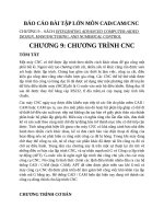
Instruction Fetch Unit at the End of Branch
31
26
op
21
16
rs
rt
0
immediate
Inst
Memory
Instruction<31:0>
Adr
nPC_sel
4
00
Adder
imm16
PC
Mux
Adder
MAC/VU-Advanced
Computer Architecture
if (Zero == 1) then
PC = PC + 4 +
SignExt[imm16]*4 ;
else PC = PC + 4
Clk
Lecture 8 – Computer H/W Design (2)
23
Instruction Fetch Unit at the End of Branch
Let’s consider the interesting case where the branch
condition Zero is true (Zero = 1).
Well, if Zero is not asserted, we will have our boring
case where PC + 4 is selected.
the
Anyway, with Branch = 1 and Zero = 1, the output of
second adder will be selected.
That is, we will add the sequential address, that is
output of the first adder, to the sign extended version
of
the immediate field, to form the branch target
address
(output of 2nd adder).
With the control signal Jump set to zero, this branch
target address will be written into the Program Counter
register (PC) at the end of the clock cycle.
MAC/VU-Advanced
Computer Architecture
Lecture 8 – Computer H/W Design (2)
24
Step 4: Given Datapath: RTL -> Control
Instruction<31:0>
Shtam Fun
<0:15>
<0:5>
Rd
<6:10>
Rs
<11:15>
Rt
<16:20>
<21:25>
Op
<26:31>
Instruction
Memory
address
Imm16
Control
nPC_sel RegWr
ExtOp ALUSrc
MemWr
ALUctr
RegDst
MemtoReg
Equal
DATA PATH
MAC/VU-Advanced
Computer Architecture
Lecture 8 – Computer H/W Design (2)
25