Wireless networks - Lecture 11: Fundamentals of cellular networks (Part 1)
Bạn đang xem bản rút gọn của tài liệu. Xem và tải ngay bản đầy đủ của tài liệu tại đây (152 KB, 22 trang )
Wireless Networks
Lecture 11
Fundamentals of Cellular Networks (Part I)
Dr. Ghalib A. Shah
1
Outlines
Review of last lecture
Cellular Concept
Frequency Reuse
Locating co-channel cells
Example
Summary of today’s lecture
2
Review of last lecture
Limitation of 3G
4G
►
►
►
►
►
►
Objectives
Issues
QoS
Security
Multimedia Service
Applications
Convergence of Cellular and WLAN
Billing Issue
Wireless Networks
3
Introduction
Early mobile system objective was to achieve a large
coverage using single high power antenna
Impossible to reuse the same frequencies in the same
coverage area.
For example, Bell mobile system in 1970 could support
maximum of 12 simultaneous calls over a thousand
square mile.
The Govt regulatory could not make spectrum
allocation proportion to the increasing demand
Became imperative to restructure the telephone system
to achieve high capacity with limited radio spectrum.
4
Cellular Concept
Cellular concept was a major breakthrough in solving
problem of spectrum congestion and user capacity
Offers high capacity without any major change in
technology
► Replacing high-power transmitter (large cell) with many lowpower transmitter (small cells) each providing service to small
► Each BS is allocated a portion of the channels.
► Nearby BS are assigned different group of channels
► So that all the available channels are distributed among the
nearby BS.
► May be reused as many times as necessary as long as the BS
using same channels are not in overlapping.
5
As the demand for service increases, the
number of BS can be increased with reduced
transmission power.
Thereby providing additional capacity with no
addition to spectrum.
This is the foundation of for all modern
wireless communication systems.
6
AMPS Architecture
7
Frequency Reuse
Relies on intelligent allocation and reuse of
channels.
A small geographical area with allocation of a
group of channels is called cell.
BS antennas are designed to achieve the
desired coverage within a cell avoiding cochannel interference.
The design process of selecting and allocating
channel groups for all the cellular BS is called
frequency reuse or frequency planning.
8
9
The hexagonal shape representing a cell is
conceptual and simplistic model of coverage.
The actual radio coverage is known as the
footprint and is determined from field
measurement, propagation prediction models
► However a regular shape is needed for systematic
system design and adaptation to future growth.
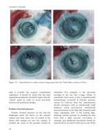
It might be natural to choose a circle to
represent coverage but adjacent circles cannot
be overlaid upon a map without leaving gaps or
creating overlapping.
10
Gaps
Overlapping
Case A
Case B
11
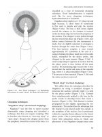
Three possible choices of shapes: square,
equilateral triangle and hexagon.
For a give distance between the center of a
polygon and its farthest perimeter points, the
hexagon has the largest area of the three
Thus by using hexagon geometry, the fewest
number of cells can cover a geographic region
and it closely approximates circle.
12
Capacity of System
When using hexagon to model coverage areas
► Center-excited Cell: BS depicted as being either in
the center of the cell
• Omni-directional antenna is used
► Edge-excited Cell: on three of the six cell vertices
• Sectored direction antenna is used
Consider a cellular system
► which has S duplex channels available for reuse.
► Each cell allocated group of k channels (k
disjoint) then
S =kN
13
Cluster: N cells, which collectively use the
complete set of available frequencies
If a cluster is replicated M times in the system,
the number of duplex channels C as a measure
of capacity is
C =MkN =MS
So capacity is directly proportional to the
replication factor in a fixed area.
Factor N is called cluster size and is typically
equal to 4, 7, 12.
14
If cluster size N is reduced while cell size is
kept constant
► more clusters are required
► More capacity is achieved
Large cluster size indicates that co-channel
cells are far from each other
Conversely, small cluster size means cochannel cells are located much closer together
The value of N is a function of how much
interference a mobile or BS can tolerate
15
Clusters are inversely proportion to N
► Capacity is directly proportional to Clusters
► Thus frequency reuse factor is given by 1/N.
In last fig, each hexagon has exactly six
equidistant neighbors and that the lines joining
the centers of any cell and its neighbors are
separated by multiple of 60 degrees.
► There are only certain cluster sizes and layouts
possible
16
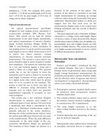
Locating co-channel neighbors
To connect hexagons without gaps,
► The geometry of hexagon is such that the number of
cells per cluster N can only have values
N =i2 +ij +j2
where i and j are non-negative integers.
To find out the nearest co-channel neighbors of
a particular cell, do the following
► Move I cells along any chain of hexagon
► Then turn 60 degree counter clockwise and move j
cells
17
Example: Locating co-channel cells
In this example N=19, i=3, j=2
18
Example
BW =33 MHz allocated to particular FDD
cellular system, where two 25 KHz simplex
channel to provide full-duplex for voice/data.
Compute the number of channels per cell if a
system uses
► Four-cell reuse
► Seven-cell reuse
► Twelve-cell reuse.
If 1 MHz is dedicated to control channels,
determine equitable distribution of control and
voice channels per cell for above three
systems?
19
Solution: Part I
TotalBW =33 MHz,
ChannelBW =25 KHz x 2 =50 KHz/duplex channel
S =33,000 / 50 =660 channels
For N =4
k =660 / 4 ≈165 channels
For N =7
k =660 / 7 ≈95 channels
For N =12
k =660 / 12 ≈55 channels
20
Solution: Part II
Sc =1000 / 50 =20 channels
Sv =S – Sc =660 – 20 =640 channels
For N=4,
5 control channels + 160 voice channel.
For N=7,
4 cells with 3 control + 92 voice channels
2 cells with 3 control + 90 voice channels
1 cell with 2 control +92 voice channels
In practice, 1 control/cell and 4x91 +3x92 voice channels
For N =12,
8 cells with 2 control + 53 voice channels
4 cells with 1 control + 54 voice channels
In practice, 1 control and 8x53 +4x54 voice channels
21
Summary
Cellular Concept
Frequency Reuse
Locating co-channel cells
Example
Next Lecture
► Handoff Strategies
► Interference and System Capacity
22