Wireless networks - Lecture 14: Fundamentals of cellular networks (Part 4)
Bạn đang xem bản rút gọn của tài liệu. Xem và tải ngay bản đầy đủ của tài liệu tại đây (961.65 KB, 27 trang )
Wireless Networks
Lecture 14
Fundamentals of Cellular Networks (Part IV)
Dr. Ghalib A. Shah
1
Outlines
Trunking and Grade of Service
► Measuring Traffic Intensity
► Trunked Systems
• Blocked Calls Cleared
• Blocked Calls Delayed
► Erlang Charts
Improving Coverage and Capacity
►
►
►
►
Cell Splitting
Sectoring
Repeaters for Range Extension
Microcell Zone Concept
2
Last lecture review
Interference and system capacity
► Co-channel interference and capacity
► Adjacent channel interference and capacity
Channel Planning for Wireless System
3
Trunking
► Allows a large number of users to share a small
number of channels
► Channel allocated per call basis from a pool of
available channels
► Relies on statistical behavior of users so that a fixed
number of channels (circuits) may accommodate a
large random user community
► Trunking theory is used to determine number of
channels for particular area (users)
► Tradeoff between the number of available channels
and likelihood of call blocking during peak calling
hours
4
Trunking Theory
► Developed by Erlang, Danish Mathematician, how a
large population can be accommodated by a limited
number of servers, in late 19th century
► Today, used to measure traffic intensity
► 1 Erlang represents the amount of traffic intensity
carried by a completely occupied channel
• i.e. one call-hour per hour or one call-minute per minute
• 0.5 Erlang: Radio channel occupied 30 minutes during 1
hour
5
Grade of Service
GOS is a benchmark used to define
performance of a particular trunked system
► Measure of the ability of a user to access trunked
system during the busiest hour.
• Busy hour is based on the demands in an hour during a
week, month or year.
• Typically occur during rush hours between 4 pm to 6 pm.
GOS is typically given as likelihood of call
blocking or delay experienced greater than
certain queue time
6
Traffic intensity
Traffic intensity is measured as call request rate multiplied by call holding
time
User traffic intensity of Au Erlang is
(1)
Au=λH
Where H is average call duration or holding time and λ is average number
of call requests.
For system of U users and unspecified channels, the total offered traffic
intensity A is
(2)
A = UAu
In a C channel trunked system, traffic equally distributed, traffic intensity
per channel Ac is
(3)
Ac= UAu/C
7
Note that traffic is not necessarily the carried traffic but
offered to the trunked system
If offered load increases the system capacity, the
carried traffic becomes limited
In Erlang, max possible carried traffic is the number of
channels C
AMPS is designed for a GOS of 2% blocking
► i.e. 2 out of 100 calls will be blocked due to channel occupancy
There are two types of commonly used trunked
systems
► Blocked Calls Cleared
► Blocked Calls Delayed
8
Block Calls Cleared
User is given immediate request if a channel is
available.
If no channel available, the requesting user is
blocked and free to try later
Assume call arrivals as Poisson Distribution
the Erlang B formula determines the probability
that call is blocked with no queuing, is a
measure of GOS for trunked system
9
Erlang B Trunking GOS
Capacity of an Erlang B System
Number of Channels
C
Capacity (Erlangs) For GOS
= 0.01
= 0.005
= 0.002
= 0.001
2
0.153
0.105
0.065
0.046
4
0.869
0.701
0.535
0.439
5
1.36
1.13
0.900
0.762
10
4.46
3.96
3.43
3.09
20
12.0
11.1
10.1
9.41
24
15.3
14.2
13.0
12.2
40
29.0
27.3
25.7
24.5
70
56.1
53.7
51.0
49.2
100
84.1
80.9
77.4
75.2
10
Erlang B
11
Block Calls Delayed
Queue is provided to hold blocked calls.
Call request may be delayed until a channel
becomes available
Its measure of GOS is defined as the
probability that a call is blocked after waiting
specific length of time in the queue
The likelihood of a call not having immediate
access is determined by Erlang C formula
12
Erlang C
13
if no channels are available immediately, the
call is delayed, probability that call is forced to
wait more than t seconds is
Average delay D in all calls in queued system
is
14
Trunking Efficiency
A measure of the number of users which can
be offered a particular GOS with particular
configuration of channels
The way channels are grouped can alter the
number of users handled
For example, From table
► 10 trunked channels at GOS of 0.01 can support
4.46 Erlang of traffic
► Whereas 2 groups of 5 channels can support
2x1.36=2.72 Erlangs of traffic, 60% lesser
15
Improving Coverage and Capacity
As demand increases, number of channels per
cell become insufficient
Cellular design techniques needed to provide
more channels per unit coverage area
Various techniques developed to expand the
capacity of system
► Cell splitting
► Sectoring
► Micro cell zone concept
16
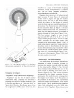
Cell Splitting
Achieve capacity improvement by decreasing R and
keeping D/R (cell reuse ratio) unchanged
Divide the congested cells into smaller cells
► Smaller cells are called micro cells
If radius of cell is cut to half, approximately four cells
would be required
► Increased number of cells would increase the number of
clusters, which in turn increase the capacity
Allows a system to grow by replacing larger cells with
smaller cells without upsetting the allocation scheme
17
18
For new cells to be smaller in size, tx power must be reduced. By
which factor?
If n =4 then the received powers equal to each other becomes
Power must be reduced by 12 dB in order to maintain S/I
requirements
19
Thus low speed and high speed users can
simultaneously handled
Channels in old cell must be broken down into
two groups corresponding to smaller and larger
cells
At beginning of cell splitting, fewer channels to
smaller power groups.
As demand grows, more channels will be
required and thus more micro cells
In the end, the whole system will be replaced
with micro cells
20
Sectoring
Keep cell radius unchanged and decrease D/R
Increases SIR so that cluster size may be
reduced
► SIR is improved using directional antennas
► Hence increasing frequency reuse without changing
transmission power
Cell is partitioned into 3 120o sectors or 6 60o
sectors as shown in Fig
21
22
23
Instead of interference from 6 cells, only 2
sectors interfere
thus S/I can be found to be 24.2 dB, where it is
17 dB in worst case presented before
This S/I improvements allow designers to
decrease cluster size N and hence enhances
capacity
Drawbacks
► Increased number of handoffs
24
Microcell Zone Concept
A cell is divided into zones with a single BS sharing the
same radio equipment
Zones are connected through coaxial cable, fiber optics
or microwave links to the BS
Superior to sectoring since antennas are placed at
outer edges of the cells and any channel may be
assigned to any zone by BS
As mobile travels from one zone to other, it retains
same channel, BS simply switches the channel to a
different zone.
Co-channel interference is minimized becuase
► Large BS is replaced by several low powered tx
► Improves S/I
25