Wireless networks - Lecture 43: IEEE 802.16 MAC/QoS
Bạn đang xem bản rút gọn của tài liệu. Xem và tải ngay bản đầy đủ của tài liệu tại đây (391.28 KB, 31 trang )
Wireless Networks
Lecture 43
IEEE 802.16 MAC/QoS
Dr. Ghalib A. Shah
1
Outlines
Reference Model
Burst profiles
Convergence sublayers
MAC PDU format
MAC PDU Transmission
Fragmentation / Packing
Request/Grant Scheme
Classes of Uplink service
Power management/Handoff
2
Outlines
WiMAX Basics
802.16 Evolution
Characteristics of 802.16
Why not 802.11 / 802.11 vs 802.16
Network Architecture
Phy Layer
► Multiple Access technique
► HARQ
► MIMO
MAC Layer
► QoS
► Power Management
► Handoff
3
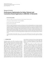
Reference Model
Scope of standard
MAC
Service Specific
Convergence Sublayer
(CS)
MAC SAP
MAC Common Part Sublayer
(MAC CPS)
Privacy Sublayer
PHY
PHY SAP
PHY Layer
(PHY)
Data/Control Plane
Management Entity
Service Specific
Convergence Sublayer
Management Entity
MAC Common Part Sublayer
Security Sublayer
Management Entity
PHY Layer
Management Plane
4
Network Management System
CS SAP
Adaptive Burst Profiles
Burst profile
►
Dynamically assigned according to link conditions
►
►
Modulation and FEC
Burst by burst, per subscriber station
Trade-off capacity vs. robustness in re al time
Roughly doubled capacity for the same cell area
Burst profile for downlink broadcast channel is well-known
5
ATM Convergence Sublayer
Support for:
► VP (Virtual Path) switched connections
► VC (Virtual Channel) switched connections
Support for end-to-end signaling of dynamically created
connections:
► SVCs
► soft PVCs
ATM header suppression
Full QoS support
6
Packet Convergence Sublayer
Initial support for Ethernet, IPv4, and IPv6
Payload header suppression
Full QoS support
Possible future support for:
► PPP
► MPLS
► etc.
7
Upon entering the network, the SS is assigned three management
connections in each direction. These three connections reflect the
three different QoS requirements used by different management
levels.
►
►
►
basic connection, which is used for the transfer of short, time-critical
MAC and radio link control (RLC) messages.
The primary management connection is used to transfer longer, more
delay-tolerant messages such as those used for authentication and
connection setup.
The secondary management connection is used for the transfer of
standards-based management messages such as DHCP, Trivial FTP,
and SNMP.
In addition to these management connections, SSs are allocated
transport connections for the contracted services.
Transport connections are unidirectional to facilitate different
uplink and downlink QoS and traffic parameters;
8
Definitions
S e rvic e Data Unit (S DU)
► Data units exchanged between adjacent layers
Pro to c o l Data Unit (PDU)
► Data units exchanged between peer entities
Co nne c tio n and Co nne c tio n ID
► a unidirectional mapping between MAC peers over the airlink
(uniquely identified by a CID)
S e rvic e Flo w and S e rvic e Flo w ID
► a unidirectional flow of MAC PDUs on a connection that
provides a particular QoS (Uniquely identified by a SFID)
9
MAC PDU format
msb
► the generic header
► bandwidth request header.
One or more MAC sub-headers may be part of the payload
The presence of sub-headers is indicated by a Type field in the
Generic MAC header field
Generic MAC Header
Payload (optional)
Isb
A MAC PDU consists of a fixed-length MAC header, a
variable-length payload, and an optional cyclic
redundancy check (CRC).
Two header formats, distinguished by the HT field, are
defined:
CRC (optional)
10
EKS (2)
LEN
msb (3)
LEN Isb (8)
CID msb (8)
CID Isb (8)
HCS (8)
Isb
Rsv (1)
Type (6)
Rsv (1)
CI (1)
HT = 0 (1) msb
EC (1)
Generic MAC Header
11
Three types of MAC subheader may be present.
► The grant management subheader
•
is used by an SS to convey bandwidth management needs to its
BS.
► The fragmentation sub-header
•
contains information that indicates the presence and orientation in
the payload of any fragments of SDUs.
► The packing sub-header
•
is used to indicate the packing of multiple SDUs into a single PDU.
The grant management and fragmentation sub-headers
may be inserted in MAC PDUs immediately following
the generic header if so indicated by the Type field.
The packing sub-header may be inserted before each
MAC SDU if so indicated by the Type field.
12
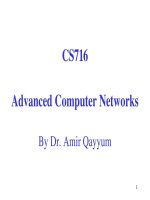
MAC PDU Transmission
MAC PDUs are transmitted in PHY bursts
A single PHY burst can contain multiple
Concate nate d MAC PDUs
The PHY burst can contain multiple FEC blocks
MAC PDUs may span FEC block boundaries
The TC layer between the MAC and the PHY
allows for capturing the start of the next MAC
PDU in case of erroneous FEC blocks
13
MAC PDU Transmission
SDU 1
MAC Message
MAC PDUs
Burst
P
PDU 1
PDU 2
FEC 1
MAC PDUs
PDU 3
FEC 2
P
Preamble
SDU 2
PDU 4
PDU 5
FEC 3
FEC block
14
Fragmentation
Partitioning a MAC SDU into fragments transported in
multiple MAC PDUs
Contents of the fragmentation sub-header:
► 2-bit Fragmentation Control (FC)
•
•
•
•
Un-fragmented
Last fragment
First fragment
Continuing fragment
► 3-bit Fragmentation Sequence Number (FSN)
•
Required to detect missing continuing fragments
15
Packing
The process of combining multiple MAC SDUs (or fragments
thereof) into a single MAC PDU
On connections with variable length MAC SDUs
On connections with fixed length MAC SDUs
Can, in certain situations, save up to 10% of system
bandwidth
16
Packing Fixed-Length SDUs
MAC Header
LEN = n*k+j
A MAC SDUs
fixed length
MAC SDU
length = n
fixed length
MAC SDU
length = n
fixed length
MAC SDU
length = n
fixed length
MAC SDU
length = n
17
Packing Variable-Length SDUs
variable length
MAC SDU
length = b
PSH
Length = c+2
variable length
MAC SDU
length = a
PSH
Length = b+2
PSH
Length = a+2
MAC Header
LEN = f
Type = 00001xb
A MAC SDUs
variable length
MAC SDU
length = c
2 Bytes Packing Sub-Header before each SDU
►
►
►
Length of SDU: 11 bits
fragmentation control (FS): 2 bits
fragmentation sequence number (FS): 3 bits
18
Downlink transmissions
Two kinds of bursts: TDM and TDMA
All bursts are identified by a DIUC
►
TDMA bursts have resync preamble
►
Downlink Interval Usage Code
allows for more flexible scheduling
Each burst may contain data for several terminals
SS must recognize the PDUs with known CIDs
DL-MAP message signals downlink usage
19
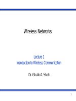
Burst profiles
C/(N+I) (dB)
Burst Profile Z
Overlap
Burst Profile Y
Each burst profile has
mandatory exit threshold and
minimum entry threshold
SS allowed to request a less
robust DIUC once above the
minimum entry level
SS must request fall back to
more robust DIUC once at
mandatory exit threshold
Requests to change DIUC done
with DBPC-REQ or RNG-REQ
messages
Overlap
Burst
Burst Profile
Profile
20
Transition to a more robust profile
SS
BS
DL data at DIUC n
RNG-REQ or DBPC-REQ
change to DIUC k
C/ (N+1)
Too Low
for
DIUC n
Yes
Continue
monitoring DL
data through
DIUC n
Send DL data
at DIUC k
DL data at DIUC k
No
RNG-RSP or DBPC-RSP
Monitor DL
data only
through
DIUC k
DL data at DIUC k
21
Request/Grant Scheme
Self Correcting
Bandwidth Requests are always per Connection
Grants are either per Connection (GPC) or per Subscriber Station
(GPSS)
22
GPSS vs. GPC
Bandwidth Grant per Subscriber Station (GPSS)
►
►
Base station grants bandwidth to the subscriber station
Subscriber station may re-distribute bandwidth among its connections,
maintaining QoS and service-level agreements
Bandwidth Grant per Connection (GPC)
►
►
Base station grants bandwidth to a connection
Higher overhead, but allows simpler subscriber station
23
Classes of Uplink Service
Unsolicited Grant Services (UGS)
Real-time Polling Services (rtPS)
Non-real-time Polling Services (nrtPS)
Best Effort (BE)
►
for best-effort traffic
24
[1]
QoS Category
Applications
QoS Specifications
UGS
Unsolicited Grant
Service
VoIP
Maximum Sustained Rate
Maximum Latency
Tolerance
Jitter Tolerance
rtPS
RealTime Polling
Service
Streaming
Audio or Video
Minimum Reserved Rate
Maximum Sustained Rate
Maximum Latency
Tolerance
Traffic Priority
ErtPS
Extended RealTime
Polling Service
Voice with
Activity
Detection
(VoIP)
Minimum Reserved Rate
Maximum Sustained Rate
Maximum Latency
Tolerance
Jitter Tolerance
Traffic Priority
nrtPS
Non RealTime Polling
Service
File Transfer
Protocol
(FTP)
Minimum Reserved Rate
Maximum Sustained Rate
Traffic Priority
BE
BestEffort Service
Data Transfer,
Web Browsing,
etc.
Maximum Sustained Rate
Traffic Priority
25