The Application of Programmable DSPs in Mobile ppt
Bạn đang xem bản rút gọn của tài liệu. Xem và tải ngay bản đầy đủ của tài liệu tại đây (4.98 MB, 409 trang )
1
Introduction
Edgar Auslander and Alan Gatherer
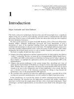
This book is about two technologies that have had, and will increasingly have, a significant
impact on the way we all live, learn and play: personal wireless communications and signal
processing. When it comes to both markets, history has shown that reality has often surprised
the most optimistic forecasters.
We draw on the experience of experts from MIT, Berkeley, UCLA, Worcester Polytechnic
Institute, INRIA, Authentec, Radioscape, Geovector and Texas Instruments, to give a
description of some of the important building blocks and implementation choices that
combine both technologies, in the past and in the future. We highlight different perspectives,
especially regarding implementation issues, in the processing of speech, audio, video, future
multimedia and location-based services as well as mobile commerce and security aspects.
The book is roughly divided into three sections:
† Chapters describing applications and their implementations on what might be described as
‘‘today’s’’ technology. By this, we mean the use of programmable Digital Signal Proces-
sors (DSPs) and ASICs in the manner in which they are being used for today’s designs. In
these chapters, we highlight the applications and the role of programmable DSPs in the
implementation.
† Chapters that present challenges to the current design flow, describing new ways of
achieving the desired degree of flexibility in a design by means other than programmable
DSPs. Whether these new approaches will unseat the programmable DSP from its perch
remains to be seen, as the commercial value of these approaches is less certain. But they
give a detailed overview of the directions researchers are taking to leap beyond the
performance curve of the programmable DSP approach.
† We conclude with a practical yet innovative application example, a possible flavor of the
exciting new personal communications services enabled by digital signal processing.
In this introduction, we overview the aspects of mobile communications that make it a
unique technology. We describe how the applications associated with mobile communica-
tions have evolved from the simple phone call into a slew of personal technologies. These
technologies, and their implementation, are described in more detail in the subsequent chap-
ters.
The Application of Programmable DSPs in Mobile Communications
Edited by Alan Gatherer and Edgar Auslander
Copyright q 2002 John Wiley & Sons Ltd
ISBNs: 0-471-48643-4 (Hardback); 0-470-84590-2 (Electronic)
1.1 It’s a Personal Matter
The social impacts and benefits of personal wireless communications are already visible.
When phones were not portable and used to only sit on a desk at home or at work, people
would call places: work or home; but when phones became portable and accessible anywhere,
people began to call people rather than places: today, when we call people we even often start
by asking ‘‘ Hello, where are you?’’ . The mobile phone has become a safety tool: ‘‘ I will bring
the phone with me in case I need to call for an emergency, if anxious family members want to
reach me, or if I am lost’’ . The mobile phone has become a social tool, enabling more flexible
personal life planning: ‘‘ I do not know where I will be at 2 p.m. and where you will be, but I
will call you on your mobile and we will sync’’ . A recent survey has shown that when people
forget their mobile phone at home, a vast majority is willing to go back home to get it, even
when it implies a 30-minute drive. The mobile phone has become a personal item you carry
with you like your wallet, your drivers’ license, your keys, or even wear, like a watch, a pen,
or glasses: it made it to the list of the few items that you carry with you. If you are a teenager,
a gaming device or an MP3 player also made their room in your pocket, and if you are a busy
executive a personal organizer is maybe more likely to have this privilege. Figure 1.1
illustrates the integration of new features trend; conversely, the wireless communication
technology will be pervasive in different end-equipments and create new markets for wireless
modules embedded in cars for example.
To some, the use of a mobile phone in public places is an annoyance. Peer pressure
‘‘ dictates’’ you have a mobile phone to be reachable ‘‘anywhere any time’’ ; not having a mobile
phone becomes anti-social in Scandinavian countries for example, where penetration is higher
than 70% of the whole population. Like for every disruptive technology widely used, a
new etiquette has to be understood and agreed upon, e.g. phones have to be turned off or put
The Application of Programmable DSPs in Mobile Communications2
Figure 1.1 Integration and exportation of functions to and from the mobile phone
in silent mode at concerts or in restaurants. Phones are now programmed with different ringing
profiles that are ‘‘ environment friendly’’ (e.g. meeting mode rings only once and makes the
phone vibrate). Inthe future, we might see phones that are environment aware, with sensors that
detect if the phone is in a bag and needs to ring louder forexample. In the past, Matra-AEG, now
Nokia Mobile Phones, introduced a GSM phone that had an infra-red sensor that served as a
proximity detector so as to put the phone automatically on or off hands-free mode. Ringing
profiles have also other nice applications: paired with CallerID, they enable users to have
different ringing tones for different callers (friends, family, business partners, unknown…).
1.2 The Super Phone?
To the vast majority, the mobile phone is the ultimate telecommunication tool, via voice or
short messages, soon to become multimedia messages or multimedia communications.
For some, it is a foregone conclusion that wireless terminals will continue their mutation
from fairly simple, voice-oriented devices to smarter and smarter systems capable of
increasingly more complex voice and data applications. The argument goes that wireless
phones will take on the capabilities of Personal Digital Assistants (PDAs) and PDAs will
subsume many of the voice communications capabilities of mobile phones. This line of
reasoning proclaims that the handsets of the future eventually will become some sort of
super-phone/handheld computer/PDA. But in the end, the marketplace is never nearly as
neat and tidy as one might imagine. Rather than an inexorable quest for a one-size-fits-all
super-phone, the fractious forces of the market, based as they are on completely illogical
human emotions, no doubt will lead handset manufacturers down a number of avenues in
support of 2.5G and 3G applications (2.5 and 3G refer to coming phone standard genera-
tions to be described later in this book). Many mobile handsets will be capable of converged
voice/data applications, but many will not. Instead, they will fulfill a perceived consumer
need or perform a certain specialized function very well. Rather than a homogenous market
of converged super-phones, the terminal devices for next generation applications will be as
diverse as they are today, if not more so. And they will be as diverse as the applications that
will make up the 2.5G and 3G marketplace. Mobile device OEMs must be prepared to meet
the challenge of a diverse and segmented market. Figure 1.2 illustrates how wireless phone
service started to be affordable to a few privileged business professionals and how it
diversified in time to become a consumer item. The high-end phone of today is the classic
phone of tomorrow as fashion and technology evolve and as people become used to inno-
vations brought to them.
We believe that the increasing need for function diversification will drive the program-
mable DSP into an even more integrated role within the mobile devices of tomorrow. Non-
programmable DSP architectures will have to take on many traits of the programmable DSP
in order to compete with it. The later chapters of this book highlight that the future of
programmable DSPs in mobile applications hinges on their ability to bring the right level
of flexibility, along with low power performance.
Over the last several years, the market for terminals first became polarized and then
stratified. The market first polarized at the high and low ends of the spectrum. As more
features and functions could be added to handsets, they were and this made up the high
end. But to attract new subscribers, wireless carriers still wanted low-end, low-cost yet robust
Introduction 3
mobile phones. In fact, for the service provider offering free handsets to each new subscriber,
the lower the cost of the handset, the better off the service provider would be.
In the last few years though, the market has shown that it will splinter and stratify with
several different layers or market segments between the poles. Some of the distinct segments
that are emerging can be defined as:
† Data-centric devices: evolving from the PDA, these advanced palmtop computers will be
integrated with cellular voice and retain or even expand upon their computing capabilities.
Data-centric devices can also be modem cards (no keyboard, no display!) that can be
plugged into laptops.
† Smart-phones: migrating from the cellular telephone segment of today’s market, smart-
phones will perform their voice communications functions quite effectively, but they also
will be equipped with larger display screens so they can begin to perform new applications
like e-mail access, Internet browsing and others.
† Fashion phones: these devices will use fashion techniques to appeal to several segments of
consumers. The businessperson, for example, will be attracted to a certain look and feel to
make a fashion statement. Younger consumers will have quite different tastes. Although
they will cross several demographic market segments, these types of phones will appeal to
buyers who are fashion-conscious and who will use fashion to make a statement about
their lifestyles.
† Classic mobile phones: for users who are looking for a workhorse mobile phone, the
classic handset will be small and easy-to-handle, and it will perform effectively the
most frequently used communications features.
The Application of Programmable DSPs in Mobile Communications4
Figure 1.2 Digital cellular phones segments dynamics
† Low-end phones: service providers will continue to offer free phones with service
contracts. These small, light and robust phones will remain a mainstay in the market
because they perform a very valuable function. They often come with a pre-paid calling
plan bundle. They attract first-time users. In the future, we might see such phones without
a keyboard or a display (to save cost): phone calls would be made via an operator sitting in
a call center or a voice dialing/recognition system, most likely in the network.
† Bluetooth-enabled phones: Bluetooth is a short range, low-cost, low power wireless tech-
nology operating in the 2.4 GHz unlicensed band. Bluetooth-enabled phones can be any of
the above categories, but the form factors may change dramatically as the phone will now
be distributed around your body.
The types of handsets that can be identified are illustrated in Figure 1.3 (concept phones
courtesy of Nokia). What is not known is what tomorrow may hold and the effects new
applications will have on the size, shape and function of future terminal devices.
One thing is for certain: new technologies will be developed that will alter the form factors
in use today. For example, a Bluetooth-enabled phone maybe a belt-attached controller/
gateway device linked to an ear piece that communicates audio information. A display
unit of some sort could be connected to the user’s eye glasses for communicating visual
data. And beyond these fairly new applications, medical sensors could be deployed to moni-
tor the person’s heartbeat or other vital functions.
A small box, comparable to a flat pager in size, will incorporate cellular and Bluetooth (or
another technology such as IEEE802.11B or IEEE802.15) functionalities combined, to
communicate with a collection of fashionable accessories; the accessories, of the size and
Introduction 5
Figure 1.3 New form factors
weight of a pen, or a flat screen for example, will form a personal area network of thin clients
communicating via Bluetooth with the small box, the Personal Mobile Gateway (Figure 1.4,
courtesy of IXI Mobile Inc.). That way the ‘‘ all-in-one’’ terminal, often too big to be a phone
and too small to be a PDA, will become a collection of smart yet thin, fashionable and low
cost devices. The concept would appeal to both mobile professionals and teenagers, the
primary target for the ever increasing replacement market.
1.3 New Services
We have discussed wireless devices, but what users really care about are the services those
devices will bring to them, and industry players care about how money will be made. Before
describing the new services that are likely to be offered thanks to personal mobile terminals, a
little history lesson will be useful and remind us to be humble, especially when it comes to
predicting the future! When the telephone was invented, it was originally to improve the
telegraph system. The fundamental idea of the electrical transmitting of sound was published
by Charles Bourseul first in 1854 in the magazine L’Illustration de Paris. Alexander Graham
Bell patented his telephone on the 14 February 1876, just 3 hours before Elisha Gray. Nobody
was interested in his invention first. When he asked the Western Telegraph Company in 1877
to buy his patent for $100,000, the response was ‘‘ What shall we do with a toy like that?’’ .
There was some doubt as to the use to which telephones might actually be put in practice.
Demonstrations often included speech, song and music, and it was not uncommon for the
musical demonstrations to be technically the most successful. ‘‘ The musical telephone’’ was a
major attraction at the International Electrical Exhibition in Paris in 1881, where the French
engineer Cle
´
ment Ader demonstrated stereophonic transmission by telephone direct from the
stages of the Paris Opera House and the Come
´
die Franc¸aise. It was believed to be the
major application of telephony. In 1890, a commercial company, Compagnie du Theatro-
phone (Figure 1.5), was established in Paris, distributing music by telephone from various
theatres to special coin-operated telephones installed in hotels, cafe
´
s, etc. and to domestic
subscribers. The service continued until 1932, when it was made obsolete by radio broad-
The Application of Programmable DSPs in Mobile Communications6
Figure 1.4 Personal Mobile Gateway
TM
(IXI Mobile Inc.)
casting. The phone has come a long way since then, and the first mass market application is
simply… talking with other people.
With the advent of the Internet and wireless data services, a new realm of possibilities are
already offered, that go far beyond ‘‘ just talking with other people’’ , as witnessed by the
recent success of NTT DoCoMo’s I-mode service in Japan. Service categories of the near
future will encompass personalized information delivery for news, location-dependant
services, travel, banking and personal hobbies; it will also include productivity-related
services such as Virtual Private Network (VPN) with the office or the family, personal
assistant, agendas, and address books; extended communication, including e-mail, postcard
transmission, and of course entertainment. Nokia has already introduced phones with games
such as ‘‘ the snake’’ , but the future will bring much more exciting games (on-line as well as
off-line, puzzles, gambling) and new forms of entertainment: music (ringtones, clips and
songs), TV (schedules, clips), chat groups, astrology, dating services and what is sometimes
called ’’ adult entertainment’’ . Figure 1.6 shows some of the service categories.
The successful deployment of the services will depend on ease of use, convenience,
pertinence, and clear affordable billing. The pertinence of the service will require persona-
lization; profiling technology can be used to match content to the needs of the users. Loca-
tion-based services will enable or facilitate such profiling. Of course localization will have to
be volunteered and ‘‘legally-correct’’ information. Most mobile location-based services today
use positioning based on Cell of Origin (COO), but the precision is often mediocre, linked to
cell size; in some cases, this is acceptable enough. Another method, known as Enhanced
Observed Time of Difference (EOTD) is used in some GSM networks. Time of arrival signals
from base stations are measured by the phone and what is called a Location-Measurement
Unit (LMU). In future UMTS systems, a similar technique will be used that is known as
Introduction 7
Figure 1.5 The Theatrophone
Observed Time Difference of Arrival (OTDOA). The location methods we just talked about
only use the network and LMUs as a means to get location information; the use of Global
Positioning System (GPS) gives better results, but the cost of a GPS receiver has to be added
to the phone. An illustration of an innovative way to exploit and present location-based
services is given in the last chapter of the book.
1.4 The Curse and Opportunity of Moore’s Law
Moore’s law predicted the rapid increase in transistor density on silicon chips. Along with this
increase in transistor density, came an increase in clock speed, chip size, and component
density on boards. All this has given the system designer an exponentially increasing amount
of processing power to play with in his or her quest for more and more sophisticated systems.
The design community has reacted to this explosion by making less and less efficient use of
the transistors offered to it. This has been true since we first moved from hand laid out
transistors to logic gates. The latter is less efficient in terms of silicon area and speed
optimization, but is much more efficient in terms of a more precious resource: human intel-
lect. From logic to RTL to microprocessors, the designer has moved to an increasingly high
level of abstraction in order to design more and more complex devices in reasonable time-
frames. Despite this, designers continue to lag behind process engineers in their ability to
consume the transistors being made available to them. This can be clearly seen in Figure 1.7
which plots the ability of a designer to use transistors against the availability of transistors
that can be used. This trend makes the use of programmable devices within mobile commu-
nications systems inevitable for the foreseeable future. The only question is, what will these
The Application of Programmable DSPs in Mobile Communications8
Figure 1.6 Service categories
programmable devices look like? Programmable DSPs are programmable devices that
include features that enable efficient implementation of systems within the special class of
signal processing problems. By focusing on signal processing DSP designers have put
programmable DSPs at the heart of many consumer devices, including mobile communica-
tion systems. Recently DSPs have been specialized to perform specifically in the domain of
signal processing for mobile communications (more details are given in Chapter 2). The
balance between specialization and flexibility is important for any DSP to succeed.
As DSPs are programmable, they are not ‘‘ just pieces of silicon,’’ they come with a
development environment. In the early 1980s, DSP was considered black magic, used by
gurus who wrote all applications in assembly language. Now, powerful development tools
including application boards, emulators, simulators, debuggers, optimizing High Level
Language (HLL) compilers, assemblers, linkers, block diagram environments, code genera-
tors, real-time operating systems (enabling easier multitasking, preemptive scheduling, high-
speed context switching, low interrupt latency, and fast, flexible intertask communication) as
well as many DSP-related books and application notes and innovative visual tools have made
DSP technology a tool for rapid design of increasingly complex systems.
In competition to DSPs, ‘‘ silicon compilers’’ have arisen. These compilers promise to take
high level descriptions of a system, and output a design ready for synthesis, usually with a
certain amount of user feedback along the way. Though such tools have shown some success
and are no doubt a useful tool in a designers arsenal, they do not provide a way to modify a
system once it has been fabricated. This is becoming an increasingly important requirement
because systems evolve quickly and are increasingly difficult to specify at design time. For
instance, a mobile handset may not be fully tested until it has been used in the field. The
increasing cost of mask sets for the fabrication of chips means any change that cannot be done
by reprogramming may cost millions of dollars and months of time. This is unacceptable in
today’s marketplace.
1.5 The Book
In this book we attempt to cover some of the important facets of mobile communications
design. We start of with five chapters covering various aspects of the design of the commu-
Introduction 9
Figure 1.7 The widening productivity gap
nications engine itself for 2G, 2.5G, and 3G phones. We then move onto the applications that
will exist on top of the communications engine, covering a wide range of applications from
video through biometric identification to security, for the next seven chapters. Then, after a
chapter on digital radio broadcast, we move onto the architecture section of the book, with
four chapters covering competitors, extensions and comparisons to programmable DSPs. The
final chapter gives a taste of the completely new applications that are waiting to be discovered
in the unique environment created when mobility meets signal processing.
We would like to thank all the contributing authors to this book for all the hard work that
went into producing the excellent chapters within. They are a great example of the expertise
and intelligence that is setting alight the field of mobile computing today.
The Application of Programmable DSPs in Mobile Communications10
2
The History of DSP Based
Architectures in Second
Generation Cellular Handsets
Alan Gatherer, Trudy Stetzler and Edgar Auslander
2.1 Introduction
Programmable Digital Signal Processors (DSPs) are pervasive in the second generation (2G)
wireless handset market for digital cellular telephony. This did not come about because
everyone agreed up front to use DSPs in handset architectures. Rather, it was a result of a
battle between competing designs in the market place. Indeed, the full extent of the use of
programmable DSPs today was probably not appreciated, even by those who were proposing
DSP use, when the 2G market began to take off.
In this chapter we present the argument from a pro-DSP perspective by looking at the
history of DSP use in digital telephony, examining the DSP based solution options for today’s
standards and looking at future trends in low power DSPs. We show that some very compel-
ling arguments in favor of the unsuitability of DSPs for 2G digital telephony turned out to be
spectacularly wrong and that, if history is to teach us anything, it is that DSP use increases as a
wireless communications standard matures. As power is the greatest potential roadblock to
increased DSP use, we summarize trends in power consumption and MIPS.
Of course, history is useless unless it tells us something about our future. Moreover, as the
DSP debate starts to rage for third generation (3G) mobile communication devices we would
like to postulate that the lessons of 2G will apply to this market also.
2.2 A History of Cellular Standards and Wireless Handset Architectures
2.2.1 1G and 2G Standards
The first commercial mobile telephone service in the US was established in 1946 in St. Louis,
Missouri. This pre-cellular system used a wide-area architecture with one transmitter cover-
ing 50 miles around a base station. The system was beset with severe capacity problems. In
The Application of Programmable DSPs in Mobile Communications
Edited by Alan Gatherer and Edgar Auslander
Copyright q 2002 John Wiley & Sons Ltd
ISBNs: 0-471-48643-4 (Hardback); 0-470-84590-2 (Electronic)
1976, Bell Mobile offered 12 channels for the entire metropolitan area of New York, serving
543 customers, with 3700 on a waiting list.
Although the concept of cellular telephony was developed by Bell Labs in 1947, it was not
until August 1981 that the first cellular mobile system began its operations in Sweden, using a
standard called Nordic Mobile Telephone system (NMT). NMT spread to Scandinavia, Spain
and Benelux. It was followed by Total Access Communication System (TACS) in Austria
(1984), Italy and the UK (1985), by C-450 in Germany (1985) and by Radiocom2000 in
France (1985). These European systems were incompatible with each other, while trans-
border roaming agreements existed between countries using the same standard (e.g.
Denmark, Finland, Norway and Sweden with NMT-450 or NMT-900 systems, and Belgium,
Luxembourg, and the Netherlands with NMT-450).
The US began cellular service in 1983 in Chicago with a single system called Advanced
Mobile Phone System (AMPS). The market situation for the US was more favorable than
Europe as a single standard provided economies of scale without incompatibility problems.
The European model became a disadvantage, pushing Europe to unify on a single digital pan-
European standard in the early 1980s and deployed in 1992. Later, this spread far beyond
Europe: Global System for Mobile telecommunications (GSM). According to the GSM
Association, more than a half billion GSM wireless phones are in use worldwide as of 11
May 2001; the standard accounts for more than 70% of all the digital wireless phones in use
worldwide and about 60% of the world’s GSM users are in Europe, but the single largest
group of GSM users is in China, which has more than 82 million users.
Ironically, while Europe went from a fragmented, multiple-standard situation to a unified
standard in the 1990s with seamless roaming structures in place (use of SIM cards), the US
went from a single standard to multiple incompatible standards (IS54/136, IS95, GSM1900)
with some inconvenient roaming schemes (use of credit cards). The IS136 operators have
recently announced (March 2001) that they will overlay their network with GSM.
All the standards that were deployed in the 1980s were analog Frequency Division Multi-
ple Access (FDMA) based, aimed at voice communication. As such, they belong to the first
generation (1G). The standards deployed in the 1990s were digital Time Division Multiple
Access (TDMA), FDMA, Frequency Division Duplex (FDD) or Code Division Multiple
Access (CDMA). These standards enabled data capabilities from 9.6 to 14.4 kb/s, and
were called 2G.
2.2.2 2.5G and 3G Standards
As demand for capabilities requiring higher data rates percolated in the mid-1990s, We
experienced the evolution of standards to 2.5G with higher data rates, enabled by multi-
slot data. High Speed Circuit Switched Data (HSCSD) is the first multi-slot data deployed.
HSCSD is circuit switched based and combines 2–8 time slots of one channel on the air
interface for each direction. The problem with circuit switched data is that circuits are
dedicated to a communication, thus ‘‘ reserved’’ to two customers for all the time of the
communication: this results in costly communication for the users and sub-optimal use of
capacity for the operators as users book circuits even if they do not use them. Another
drawback of the technology, is that a RAS connection is needed before each data connection,
and a bad communication can result in dropping the data communication all together, forcing
the user to redial the RAS connection and paying for all the wasted time for the poor
The Application of Programmable DSPs in Mobile Communications12
connection. Packet data enables these problems to be overcome, as packets of data belonging
to different users can be distributed during what would be idle times in a circuit switched
model; this enables billing to be based on data transferred rather than time, allowing better
user experience and an always-on-always-connected model; a little bit like the difference
between a RAS connection to Internet with a 14 kb/s modem and an always on connection
with DSL or cable. The first real successful deployment of wireless packet data has been
demonstrated with NTT DoCoMo’s I-mode service, which relies on PDC-P (PDC-Packet
data, where PDC stands for personal digital communications, the major Japanese digital
cellular 2G standard).
GSM packet data standard is known as General Packet Radio Service (GPRS). GPRS was
anticipated to be deployed in 2000 but will in practice be really used commercially in
4Q2001. In theory, data rates could be as high as 115 kb/s, but in practice, we will rather
experience up to 50 kb/s. Enhanced Data rate for Global Evolution (EDGE) can be imple-
mented over GPRS for even higher data rates, up to 384 kb/s, as a result of a change in the
modulation scheme used. Next, 3G, driven by data applications, supports multi-mode and
multi-band for Universal Mobile Telecommunication System (UMTS)/GSM as well as
CDMA2000/IS95. 3G was supposed to be a single ‘‘ converged standard’’ under the FPLMTS
initiative, soon re-named IMT2000 and the 3GPP initiative; but then came 3GPP2 as the
world could not agree on a single standard… after all, even though Esperanto was a good
concept, historical, political and economical reasons are such that very few people do speak
that language! The world of cellular will remain multi-mode, multi-band and complex. Figure
2.1 illustrates the path from 1G to 3G systems.
The 3G wireless systems will be deployed first in Japan in mid-2001 for capacity reasons
and later in the rest of the world mainly for wireless multimedia, and will deliver a speed up to
2 Mb/s for stationary or 384 kb/s for mobile applications. Many questions remain as far as
profitability and business models are concerned, so actual deployment might take longer than
anticipated.
The History of DSP Based Architectures in Second Generation Cellular Handsets 13
Figure 2.1 From 1G to 3G
The applications anticipated for 2.5G and 3G will require terminals to move from a closed
architecture to an open programmable platform (for details, read Chapter 7).
2.2.3 Architecture Evolution
As we mentioned in the introduction, there is a continuing debate over the role of DSPs in
wireless communications. To provide a historical basis for our arguments, in this section we
examine the case of GSM evolution. The assumption is, of course, that 3G products will
evolve in a similar manner to GSM, which is in itself debatable, but we believe that history
does have some good points to make with respect to 3G.
A common functional block diagram of a GSM system is given in Figure 2.2. We recog-
nize a classical digital communication model with signal compression, error correction,
encryption, modulation, and equalization [11]. In the early days of GSM it was assumed
that the low power requirement would mean that most of the phone would be implemented in
ASIC. In what follows we show that the power difference between DSP and ASIC was not
significant enough compared to other factors that were driving GSM phone evolution.
2.2.3.1 Mission Creep
The early GSM phones were mostly ASIC designs. However, attempts to design vocoders
with standard ASIC design techniques were not very successful and the voice coder was the
part of the architecture that most engineers agreed should be done on a DSP. Hence, in early
designs the DSP was included mainly to do the vocoding. The coder used in GSM phase 1
compressed the speech signal at 13 kb/s using the Regular Pulse Excited Linear Predictive
Coding with Long Term Prediction (RPE-LTP) technique as per GSM 06-10 specification. So
the DSP migrated from the vocoder engine to the central role as seen in Figure 2.2 over a
period of a few years. Why did this happen?
The Application of Programmable DSPs in Mobile Communications14
Figure 2.2 Functional block diagram of a GSM phone
One reason is that once a programmable device gets its ‘‘foot in the door’’ of an architecture
a certain amount of ‘‘ mission creep’’ starts to occur. The DSP takes on more functionality that
was previously done in ASIC. Why this happens is a debatable subject, but the authors
believe that several factors can be identified:
† DSPs harness process improvement more rapidly than ASIC. This is because the DSP
tends to be hand designed by a much larger team than one would normally find on one
ASIC block. This is a side effect of the amortization of the cost of DSP development over
several markets.
† DSP scale better with process improvement. This is because a programmable device, when
migrating to a higher clock rate, is capable of increased functionality. Many ASIC designs
on the other hand do not gain functionality with increased clock speed. An example might
be a hardware equalizer that is a straightforward ASIC filter implementation. If this device
is run faster, it is just an equalizer that runs too fast. Even if you wish to perform another
equalization task with the same device, you will probably have to redesign and add a
considerable amount of control logic to allow the device to time share between two
equalization operations. Indeed, in order to achieve future proof flexibility, ASIC
designers tend towards development of devices with a degree of programmability. This
increases the design effort considerably. Recently there has been a flurry of reconfigurable
architecture proposals (for instance, Chapter 17) that are trying to bridge the gap between
the efficiency of ASIC and the programmability of DSP, without the associated design
cost.
† DSPs are multitasking devices. A DSP is a general purpose device. As process technology
improves, two different functions that were performed on two DSPs, can now be
performed on a single DSP by merging the code. This is not possible with ASIC design.
The development of operating systems (OS) and real time OS (RTOS) for DSPs also have
reduced the development costs of multitasking considerably. After 1994, a single DSP was
powerful enough to do all the DSP baseband functions, making the argument for a DSP
only solution for the baseband even more compelling.
† DSPs are a lower risk solution. Programmable devices can react to changes in algorithms
and bug fixes much more rapidly, and with much lower development costs. DSPs also tend
to be used to develop platforms that support several handset designs, so that changes can
be applied to all handset designs at once. Testing of DSP solutions is also easier than ASIC
solutions.
2.2.3.2 The Need for Flexibility
Flexibility was also important in the evolving standard. GSM phase 2 saw the introduction of
Half Rate (HR) and Enhanced Full Rate (EFR). HR was supposed to achieve further compres-
sion at a rate of 5.6 kb/s for the same subjective quality, but at the expense of an increased
complexity and EFR had to provide better audio qualities and better tandeming performance,
also at the expense of higher complexity, using an enhanced Vector-Sum Excited Linear
Prediction (VSELP) algorithm. Along with these changes came changes in the implementa-
tion of the physical layer as better performance, cost, and power savings combinations were
found. As a result, each generation of phone had a slightly different physical layer from the
previous, and upgrades to ASIC based solutions became costly and difficult.
The History of DSP Based Architectures in Second Generation Cellular Handsets 15
A good example of this is the evolution of the adaptive equalizer in the GSM receiver, from
a simple Least Mean Squares (LMS) based linear equalizer through Recursive Least Squares
(RLS) adaptation to maximum likelihood sequence estimators. Indeed the performance of
adaptive equalizers and channel estimators is difficult to predict without field trials, as the
models used for the channel are only approximate. Implementation of equalization varies
from company to company and has changed over time within companies. This comment also
applies to other adaptive algorithms within the physical layer, such as timing recovery and
frequency estimation. None of these algorithms appear within the standards as they do not
affect the transmitted signal. Each company therefore developed their own techniques based
on what was available in the literature.
Because the DSPs were now being designed with low power wireless applications in mind,
the power savings to be had from ASIC implementation of the DSP functions were not
significant enough that system designers were willing to live with the lack of flexibility.
To improve system power consumption and board space, several DSPs such as the Motorola
56652 [1] and the Texas Instruments Digital Baseband Platform [2] integrate a RISC micro-
controller to handle the protocol and man–machine interface tasks to free the DSP for
communication algorithm tasks. The presently most popular partitioning of GSM is shown
in Figure 2.3. Apart from algorithmic changes, the DSP was seen as an attractive component
for a handset architecture for the following reasons:
† As GSM phones have evolved they have gradually moved beyond the simple phone function
and this has lead to an increase in the fraction of the DSP MIPs used by something other than
physical layer 1. This evolution is shown in Figure 2.4. With the advent of wireless data
applications and the increased bandwidth of 3G we expect this trend to accelerate.
† Flexibility is also required when the product life cycle decreases. It becomes more and
more difficult to manage the development of new and more complex devices in shorter and
shorter time periods, even if the cost of development is not an issue. In GSM the product
life cycle shortened from 2.5 years to 1 year thanks to the phone becoming a personal
fashion statement.
The Application of Programmable DSPs in Mobile Communications16
Figure 2.3 GSM function partitioning
† Different worldwide standards related to GSM and the need for product families addres-
sing different market segments called for a platform based architecture so that OEMs could
spin different products quickly. Development of a platform based system implies that the
platform is also flexible in order to implement several standards. This is hard to achieve
without some level of programmability.
† A DSP based baseband approach can cope better with different RF and mixed-signal
offerings which occur due to technology improvements and market changes (e.g. AGC
and AFC will change with different front ends).
† Spare DSP MIPS come for free and enable product differentiation (echo cancellation,
speech recognition, noise cancellation, better equalizers).
2.3 Trends in Low Power DSPs
DSPs continue to evolve and compete with each other for the lucrative wireless market.
Performance improvement can be achieved in several ways. Process improvement, instruc-
tion set enhancement and development of effective peripherals (such as DMA and serial
ports) are three important ways to improve the performance of the device. Of course devel-
opment of better software tools for development, debugging and simulation of DSP code
cannot be underestimated as an incentive to pick one DSP over another.
2.3.1 Process Improvement
The digital baseband section is critical to the success of wireless handsets and, as we saw in
Section 2.2, programmable DSPs are essential to providing a cost-effective, flexible upgrade
path for the variety of evolving standards. Architecture, design, and process enhancements
are producing new generations of processors that provide high performance while maintain-
ing the low power dissipation necessary for battery powered applications. Many communica-
tions algorithms are Multiply-Accumulate (MuAcc) intensive. Therefore, we evaluate DSP
power dissipation using mW/MMuAcc, where a MuAcc consists of fetching two operands
The History of DSP Based Architectures in Second Generation Cellular Handsets 17
Figure 2.4 Layer 1 and application MIPS with time
from memory, performing a MuAcc, and storing the result back in memory. A MMuAcc is 1
million MuAccs. As shown in Figure 2.5, DSP power dissipation is following a trend of
halving the power every 18 months [3]. As the industry shifts from 2G to 3G wireless we are
seeing the percentage of the physical layer MIPs that reside in the DSP going from essentially
100% in today’s technology for GSM to about 10% for WCDMA. However, the trend shown
in Figure 2.5 along with more efficient architectures and enhanced instructions sets implies
that the DSP of 3 years from now will be able to implement a full WCDMA physical layer
with about the same power consumption as today’s GSM phones.
Since these DSPs use static logic, the main power consumption is charging and discharging
load capacitors on the device when the device is clocked. This dynamic (or switching) power
dissipation is given by:
Power ¼
a
C £ V
swing
V
supply
£ f
where
a
is the number of times an internal node cycles each clock cycle, and V
swing
is
usually equal to V
supply
. The dynamic power for the whole chip is the sum of this power
over all the nodes in the circuit. Since this power is proportional to the voltage squared,
decreasing the supply voltage has the most significant impact on power. For example,
lowering the voltage from 3.3 to 1.8 V decreases the power dissipation by a factor of
3.4. However, if the technology is constant, then lowering the supply voltage also decreases
performance. Therefore, technology scaling (which decreases capacitance) and power
supply scaling are combined to improve performance while decreasing the total power
consumption of the DSP. In addition, parallelism can be used to increase the number of
The Application of Programmable DSPs in Mobile Communications18
Figure 2.5 Power dissipation trends in DSP
MuAcc operations that can be performed in a single cycle, further improving processor
efficiency as shown in Figure 2.6. This combination of techniques is used to enable the
current TMS320C55x to achieve 400 MMuAccs at 1.5 V and 0.25 mW/MMuAcc in 0.15
mm CMOS technology.
2.3.2 Instruction Set Enhancement
In what follows we use the TI TMS320C55x [4,5] as an example of an evolving DSP that is
optimized for wireless applications. However, the reader should note that because of the
growing importance of the wireless market (more than 400 million units projected for 2000
[6]), there are now several DSPs on the market that have been designed with wireless
applications in mind, for instance the Agere Systems (formally Lucent) 16000 series [7]
and the ADI21xx series. IBM has also announced a TMS320C54x clone. This level of effort
by several companies is a sign that the collective wisdom of the marketplace has chosen to bet
on a programmable DSP future for wireless technology. We should also note that though
designed for wireless applications, these DSPs are finding major markets in other low power
applications such as telephony modems, digital still camera, and solid-state audio players.
As was mentioned in Section 2.2, the power difference between DSP and ASIC solutions
was significantly reduced by designing the DSP for low power wireless applications. Several
power saving features are built into the TMS320C55x architecture and instruction set to
The History of DSP Based Architectures in Second Generation Cellular Handsets 19
Figure 2.6 C5000 power vs. MMuAccs
reduce the code size and processor cycles required. The core uses a modified Harvard
architecture that incorporates five data memory buses (three read, two write), one program
memory bus, and six address buses. This architecture leads to high memory bandwidth and
enables multiple operand operations, resulting in fewer cycles to complete the same function.
The TMS320C55x also contains two MuAcc units, each capable of a 17-bit £ 17-bit multi-
plication in a single cycle. The central 40-bit Arithmetic/Logic Unit (ALU) can be split to
perform dual 16-bit operations, and it is supplemented with an additional 16-bit ALU. Use of
the ALU instructions is under instruction set control, providing the ability to optimize parallel
activity and power management.
Another strategy used by DSP designers is to add instructions that, though fairly
generic in themselves, allow efficient implementation of algorithms important to wireless
applications. For instance in the TMS320C55x, one of the ALU inputs can be taken from
a 40-bit barrel shifter, allowing the processor to perform numerical scaling, bit extraction,
extended arithmetic, and overflow prevention. The shifter and exponent detector enable
single-cycle normalization of values and exponential encoding to support floating-point
arithmetic for voice coding. A compare-select-store unit contains an accelerator that, for
channel decoding, reduces the Viterbi ‘‘ butterfly update’’ to three cycles. This unit gener-
ally provides acceleration for any convolutional code based on a single shift register,
which accounts for all the codes commonly in use in wireless applications today. Using
this hardware accelerator, it is possible to decode one frame of a GSM voice channel
(189 values) with coding rate 1/2 and constraint length 5 in approximately 6800 cycles,
including traceback. The TMS320C55x also contains core level multimedia-specific
extensions, which facilitate the demands of the multimedia market for real-time, low-
power processing of streaming video and audio. There are also three hardware accelera-
tors for motion estimation, Discrete Cosine Transform (DCT), Inverse Discrete Cosine
Transform (IDCT) and 1/2-pixel interpolation to improve the efficiency of video applica-
tions. In addition, it contains four additional data registers that can be used with the 16-bit
ALU for simple arithmetic and logical operations typical of control code, avoiding the
use of higher power units.
The TMS320C55x instruction set also contains several dedicated instructions including
single and block repeat, block memory move, conditional instructions, Euclidean distance
calculation, Finite Impulse Response (FIR) and LMS filtering operations. The trend towards
more specialized instructions will continue increasing as the cost of supporting these instruc-
tions goes down. Other instruction enhancements for bit manipulation, which is traditionally
done much more efficiently in ASIC, will occur in the near future.
Another trend in DSP evolution is towards VLIW processors to support a compiler based,
programmer friendly environment. Examples of this include TI’s TMS320C6x [8], ADI’s
TigerSHARC [9] and Agere Systems and Motorola’s Star*Core [10]. These VLIW proces-
sors use Explicitly Parallel Instruction Computing (EPIC) with predication and speculation to
aid the compilers. The processors are also statically scheduled, multiple-issue implementa-
tions to exploit the instruction level parallelism inherent in many DSP applications. Though
the application of this to physical layer processing in the handset is not apparent so far, these
devices allow very efficient compilation of higher level code so reducing the need for DSP
specific assembly level coding of algorithms. As explained in Chapter 7, the trend of wireless
towards an open, applications driven system will make this kind of DSP much more compel-
ling as a multimedia processor in the handset.
The Application of Programmable DSPs in Mobile Communications20
2.3.3 Power Management
Power management is very important in a low power DSP and several new advanced power
management methods are implemented in the TMS320C55x. First, the TMS320C55x moni-
tors all the peripherals, memory arrays, and individual CPU units and automatically powers
down any units not in use. Memory accesses are reduced through the use of a 32-bit program
bus and instruction cache with burst fill to minimize off-chip accesses. In addition, the user
can configure the TMS320C55x processor for 64 combinations enabling or disabling six key
functional domains: CPU, instruction cache, peripherals, DMA, clock generator, and External
Memory Interface (EMIF). This enables customization of the power consumption for a
specific application. The TMS320C55x also supports variable length instructions, from 8
bits to 48 bits, to allow optimization of code density and power consumption. The instruction
buffer automatically unpacks the instructions to make the most efficient use of each clock
cycle. The reduction in DSP core memory bus activity decreases the power consumption
while longer instructions can carry out more functions per clock cycle. A flexible digital PLL
based clock generator and multiplier allows the user to optimize the frequency and power for
their application. In general these techniques allow a DSP that is not designed for a specific
function to optimize its power usage for that function bringing its power level closer to that of
a dedicated ASIC design.
References
[1] />[2] />[3] Gelabert, P. and Stetzler, T., Industry’s Lowest Power General Purpose DSP, Embedded Processor Forum, 3–4
May 1999.
[4] TMS320C55x Technical Overview, Texas Instruments, Literature Number SPRU393, February 2000.
[5] TMS320C55x Functional Overview, Texas Instruments, Literature Number SPRU312, June 2000.
[6] Dataquest, Mobile Communications Semiconductor Applications Markets, 1997–2002, 12 April 1999, WSAM-
WW-MT-9901.
[7] />[8] />[9] />[10] />[11] Auslander, E. and Couvrat, M., Take the LEAD in GSM, in ’Applications of Digital Signal Processing’,
Proceedings of DSP94 UK, 1994, and in Technologist Proceedings, Herzlya, Israel, November 1995.
The History of DSP Based Architectures in Second Generation Cellular Handsets 21
3
The Role of Programmable DSPs
in Dual Mode (2G and 3G)
Handsets
Chaitali Sengupta, Nicolas Veau, Sundararajan Sriram, Zhenguo Gu and Paul
Folacci
3.1 Introduction
Third generation (3G) mobile radio standards are the result of a massive worldwide effort
involving many companies since the mid-1990s. These systems will support a wide range of
services, with voice and low rate data to high data rate services up to 144 Kbps in vehicular
outdoor environments, 384 Kbps in pedestrian outdoor environments, and 2 Mbps in indoor
environments. Both circuit and packet switched services with variable quality of service
requirements will be supported.
The key challenges in designing 3G modems arise from the signal processing dictated by
the underlying CDMA-based air interface with a chip rate of 3.84 Mcps (for the FDD DS
mode explained later), the high data rate requirements, and the multiple and variable rate
services that need to be supported simultaneously. Due to the various service scenarios – low-
end voice to high-end high data rate – flexibility of the design is imperative.
In telecommunications, a ‘‘multi-mode’’ mobile is one that can support many different
telecommunication standards with different radio access technologies. For example, the dual-
band mobiles GSM 1 DCS are not considered as multi-mode mobiles because it uses the
same radio access technology and the difference is only on the frequencies. By looking at the
origin of the dual-mode system, we find two main drivers.
Operator driven: when ETSI developed the GSM specifications, it wasn’t expected that the
second generation (2G) mobile would be backward compatible with their analog 1G counter-
parts. This was acceptable because the number of 1G users was negligible compared to the
forecasted 2G users. On the other hand, in the 1980s it was quite easy for the small number of
European members to agree on a single radio access technology because nobody then had an
existing digital cellular network, so no compatibility was required. But when the success of
GSM expanded outside Europe, the constraints changed and some operators decided to
The Application of Programmable DSPs in Mobile Communications
Edited by Alan Gatherer and Edgar Auslander
Copyright q 2002 John Wiley & Sons Ltd
ISBNs: 0-471-48643-4 (Hardback); 0-470-84590-2 (Electronic)
couple other standards with GSM. The main examples are GSM 1 DECT, GSM 1 AMPS,
and GSM 1 ICO. However, such dual subsystems were not well adapted to allow a good
integration for lowering the cost and reducing the size, and the two standards weren’t allowed
seamless handover.
Standardization committee driven: for the 3G Partnership Project (3GPP), the objective
was to build an international standard with the ambition that a mobile could be used anywhere
on the earth. The best solution was to agree on a single radio access technology for all the
countries in the world. This was unfortunately impossible because it was too difficult to find a
single radio access technology which could be backward compliant with all the different 2G
radio access technologies already used by billions of customers all around the world. The best
solution found by 3GPP to be backward compatible with 2G and allow a global roaming was
to select a few radio access technologies (five) and to specify the mechanisms to allow
intersystem handover. This solution is technically very difficult and needs to overcome
many problems. But this solution compared to the operator driven one has more chance of
leading us towards a viable solution.
From an operator point of view, the multi-mode mobile has many advantages. When an
operator buys a UMTS license it gets the authorization to use the five possible air interfaces in
its band. Depending on its strategy, the multi-mode could exploit many configurations. If the
operator already has a 2G network (most cases), it could protect its 2G network investment
(and its 2G mobile users) by using a dual-mode mobile. It also permits a smooth transition
from 2G to 3G. The last interest is to increase its capacity and its coverage.
In this chapter we focus on the 3G FDD DS option as defined by 3GPP. This option is most
likely to be the first deployed 3G mode. We present the salient features of the 3GPP FDD DS
(popularly called WCDMA) mode followed by an overview of the requirements for the 3G-
handset architecture and the role of a programmable DSP to meet those requirements as well
as that of a GSM/WCDMA dual mode handset.
3.2 The Wireless Standards
Since the 3G standardization activities began [1–3], three main parallel development efforts
have progressed in Europe (ETSI), Japan (ARIB) and the US. However, through the harmo-
nization efforts of several groups, there are now three (harmonized) modes of the 3G standard
(Table 3.1).
The FDD-DS mode is widely accepted as the mode that will be deployed first starting in
Japan in 2001. In the rest of the chapter, we base our discussions about design of a 3G
handset, on this mode. Table 3.2 lists the salient features of this mode. Table 3.3 lists the
salient features of GSM.
The Application of Programmable DSPs in Mobile Communications24
Table 3.1 The three CDMA based modes of 3G
Parameter Mode 1: FDD
direct sequence
Mode 2: FDD
multi-carrier
Mode 3: TDD
Chip rate (Mcps) 3.84 3 £ 1.2288 3.84
Channel structure Direct spread Multi-carrier Direct spread
Spectrum allocation Paired bands Paired bands Unpaired band
The key features of the 2.5G and 3G standards illustrate the major differences between the
two. Later we will highlight the commonalities between the two and the operation of inter-
system measurements and handover.
3.3 A generic FDD DS Digital Baseband (DBB) – Functional View
The radio interface is layered into three protocol layers:
† Physical layer (Layer 1), responsible for data transfer over the air interface.
† Data link layer (Layer 2), responsible for determining the characteristics of the data being
transferred, such as, handling data flow and quality of service requirements. The MAC is
the Layer 2 entity that passes data to and from Layer 1.
† Network layer (Layer 3), responsible for control exchange between the handset and the
UTRAN, and allocating radio resources. RRC is the Layer 3 entity that controls and
allocates radio resources in Layer 1.
In this chapter, we will concentrate on the physical layer receiver processing, the most
demanding layer in terms of hardware–software resources, and real-time constraints. Also we
will not talk about the RF and analog portions that convert the radio signal at the antenna to a
suitable stream of bits for DBB processing.
Figure 3.1 presents an overview of the various functional components of the physical layer
processing in digital baseband. The rest of this section describes the main processing modules
The Role of Programmable DSPs in Dual Mode (2G and 3G) Handsets 25
Table 3.2 Parameters defining the FDD-DS (WCDMA) 3G standard
Parameter Description/value
Carrier spacing (MHz) 5
Physical frame length (ms) 10
Spreading factor 2
k
, k ¼ 2–8: uplink, 2
k
, k ¼ 2–9: downlink
Channel coding Convolutional and Turbo
Multirate Variable spreading and multicode
Diversity techniques Multiple transmit antennas, multipath
Maximum data rates 384 Kbps outdoor, 2 Mbps indoor
Table 3.3 Parameters defining the GSM (2G) standard
Parameter Description/value (GSM)
Multiple access TDMA/FDMA
Channel spacing (kHz) 200
Physical frame length (ms) 4.615
Channel coding Convolutional
Multirate None
Diversity techniques Frequency hopping
Maximum data rates 9.6/14.4 Kbps (2.5G/GPRS: 171.2 Kbps)
in the receiver section, which is the more demanding part of the modem in terms of resource
requirements.
Despreading: the despreading process consists of correlating the complex input data with
the channelization code (Walsh code) and scrambling code, and dumping the result every SF
chips, where SF is the spreading factor. Every significant received path of every downlink
physical channel must be despread. Whether a path is significant depends upon the strength of
the path compared to the strongest path.
Maximal ratio combination: one of the properties of CDMA signals is their pseudo-noise
behavior due to the spreading process. As a result, signal paths that are separated by more
than one chip interval appear uncorrelated. Maximal Ratio Combining (MRC) is the process
of combining such paths to exploit time diversity against fading and increase the effective
SNR. The contribution from each path to the final decision statistic is proportional to its SNR.
The MRC step also needs to take into account any forms of antenna diversity in use.
Multipath search or Delay Profile Estimation (DPE): once the cell search unit has provided
the strongest path that the mobile receives from a base station, the mobile must be able to find
the next strongest paths in the vicinity of the main path, in order to perform maximal ratio
combining. To facilitate soft hand-off, multipath search must be performed simultaneously
for several base stations.
CCTrCH processing: in the downlink transmitter at the base station, data arrives from the
MAC (Layer 2 entity) to the coding/multiplexing unit in the form of transport block sets once
every transmission time interval {10 ms, 20 ms, 40 ms, and 80 ms}. In the handset receiver,
The Application of Programmable DSPs in Mobile Communications26
Figure 3.1 Functional overview of physical layer processing in DBB