Image-Guided Spine Interventions pot
Bạn đang xem bản rút gọn của tài liệu. Xem và tải ngay bản đầy đủ của tài liệu tại đây (27.67 MB, 386 trang )
Image-Guided
Spine InterventionsImage-Guided
Spine Interventions
Editor
John M. Mathis, MD, MSc
Chairman, Department of Radiology, Lewis-Gale Medical Center, Salem, Virginia;
Professor and Chairman, Department of Radiology, Virginia College of
Osteopathic Medicine, Blacksburg, Virginia
Associate Editors
Blake A. Johnson, MD
Associate Editor, Spine Radiology
Peter S. Staats, MD
Associate Editor, Pain Anesthesia
F. Todd Wetzel, MD
Associate Editor, Spine Orthopedics
With 189 Illustrations in 292 Parts, 39 in Full Color
Library of Congress Cataloging-in-Publication Data
Mathis, John M.
Image-guided spine interventions / John M. Mathis.
p. cm.
Includes index.
ISBN 0-387-40320-5 (alk. paper)
1. Spine—imaging. 2. Spine—Surgery. 3. Surgery—Data processing. I. Title.
RD768.M388 2003
617.5Ј6–dc21 2003052966
ISBN 0-387-40320-5 Printed on acid-free paper.
© 2004 Springer-Verlag New York, Inc.
All rights reserved. This work may not be translated or copied in whole or in part without the written permission
of the publisher (Springer-Verlag New York, Inc., 175 Fifth Avenue, New York, NY 10010, USA), except for brief
excerpts in connection with reviews or scholarly analysis. Use in connection with any form of information storage
and retrieval, electronic adaptation, computer software, or by similar or dissimilar methodology now known or
hereafter developed is forbidden.
The use in this publication of trade names, trademarks, service marks, and similar terms, even if they are not iden-
tified as such, is not to be taken as an expression of opinion as to whether or not they are subject to proprietary
rights.
While the advice and information in this book are believed to be true and accurate at the date of going to press,
neither the authors nor the editors nor the publisher can accept any legal responsibility for any errors or omissions
that may be made. The publisher makes no warranty, express or implied, with respect to the material contained
herein.
Printed in the United States of America.
9 8 7 6 5 4 3 2 1 SPIN 10936368
www.springer-ny.com
Springer-Verlag New York Berlin Heidelberg
A member of BertelsmannSpringer Science
ϩ
Business Media GmbH
John M. Mathis, MD, MSc
Chairman
Department of Radiology
Lewis-Gale Medical Center
Salem, VA 24153
and
Professor and Chairman
Department of Radiology
Virginia College of Osteopathic Medicine
Blacksburg, VA 24060
USA
To the women in my life who make all things possible:
Krista, Jamie, Juanita, Jean, Ida, Mildred, and Vernice.
v
This page intentionally left blank
The field of interventional radiology is constantly undergoing change,
and its procedures evolve over time. There is currently tremendous
pressure on our specialty, as cardiology and vascular surgery appro-
priate existing vascular interventions. We need to be looking constantly
for new procedures that will replace this loss. In the 1980s, the intro-
duction of vascular access provided new procedures that included the
placement of temporary venous catheters, ports, tunneled catheters,
and dialysis maintenance. As a result of vascular access the number of
procedures performed in some interventional labs doubled. The same
revolution is occurring again with the advent of image-guided spine
intervention. Five percent of the American population at any one time
has back pain. This huge patient population is seeking help for this
disabling and persistent problem.
Image-Guided Spine Interventions describes the varied and numerous
procedures that are available to the image-guided interventionist, who
may provide these therapies for the spine. This book embraces clinical
evaluation, pharmacological requirements, procedural recommenda-
tions, and a spectrum of procedures that will be of interest to the
image-guided spine interventionist. It covers a broad range of mate-
rial that is presented by experts in each field, including discography,
intradiscal electrothermal therapy (IDET), percutaneous discectomy,
vertebroplasty and ballon kyphoplasty, epidural steroid injections, se-
lective nerve root blocks and autonomic nerve blockade, diagnostic
epidurography and therapeutic epidurolysis, sacroiliac and facet joint
injections, implanted drug delivery systems, and epidural blood and
fibrin patches for CSF leaks. Some of the techniques described, such
as ozone therapy are expected to evolve further in the next decade.
This book will be useful to all physicians who deal with back pain, in-
cluding pain anesthesiologists, spine neurosurgeons, orthopedists,
and radiologists.
As a previous president of the American Society of Spine Radiology
and as a physician who has worked to develop image-guided spine in-
tervention in academic and clinical practice, my entire practice is now
Preface
vii
devoted to providing these interventions. My clinical practice has more
than doubled because of the introduction of these spine procedures.
This is the next huge opportunity for the image-guided interventional
community. I sincerely hope this work will be useful in helping you
establish and grow a minimally invasive spine interventional practice.
It has been a rewarding area for me.
John M. Mathis, MD, MSc
viii Preface
Preface vii
Contributors xi
1 Spine Anatomy 1
John M. Mathis, Ali Shaibani, and Ajay K. Wakhloo
2 Materials Used in Image-Guided Spine Interventions 27
John M. Mathis
3 Patient Evaluation and Criteria for Procedure Selection 37
Paul J. Christo and Peter S. Staats
4 The Surgeon’s Perspective: Image-Guided Therapy
and Its Relationship to Conventional Surgical Management 53
F. Todd Wetzel and Frank M. Phillips
5 Image-Guided Percutaneous Spine Biopsy 69
A. Orlando Ortiz and Gregg H. Zoarski
6 Discography 94
Kurt P. Schellhas
7 Intradiscal Electrothermal Annuloplasty 121
Timothy S. Eckel
8 Automated Percutaneous Lumbar Discectomy in the
Treatment of Herniated Discs 137
Gary Onik and Wendell A. Gibby
9 Epidural Steroid Injections and Selective Nerve Blocks 149
Blake A. Johnson
10 Diagnostic Epidurography and Therapeutic Epidurolysis 171
K. Dean Willis
Contents
ix
11 Facet Joint Injections 203
Timothy S. Eckel
12 Autonomic Nerve Blockade 219
Wade Wong and John M. Mathis
13 Sacroiliac Joint Injection 234
M.J.B. Stallmeyer and Gregg H. Zoarski
14 Percutaneous Vertebroplasty 245
John M. Mathis
15 Implanted Drug Delivery Systems 273
John C. Oakley
16 Endovascular Therapy of the Spine 292
Ali Shaibani and Ajay K. Wakhloo
17 Epidural Blood and Fibrin Patches 322
Lisa Watanabe
18 Balloon Kyphoplasty 334
John M. Mathis, Wayne J. Olan, and Stephen M. Belkoff
19 Intradiscal Oxygen-Ozone in the Treatment of
Herniated Lumbar Disc 349
Mario Muto, Cosma Andreula, and Marco Leonardi
Index 359
x Contents
Cosma Andreula, MD
Department of Neuroradiology, A.O. Policlinico-Anthea Hospital,
Bari 70124, Italy
Stephen M. Belkoff, PhD
Department of Orthopaedic Surgery, The Johns Hopkins University,
Baltimore, MD 21224, USA
Paul J. Christo, MD
Department of Anesthesiology and Critical Care Medicine, The Johns
Hopkins University School of Medicine, Baltimore, MD 21205, USA
Timothy S. Eckel, MS, MD
Division of Neuroradiology, Annapolis Radiology Associates,
Annapolis, MD 21401, USA
Wendell A. Gibby, MD
Department of Radiology, Riverwoods Advanced Diagnostic
Imaging Center, Provo, UT 84604, USA
Blake A. Johnson, MD
Department of Radiology, University of Minnesota Medical School,
Minneapolis, MN 55455; Director of CNS Imaging, Center for
Diagnostic Imaging, St. Louis Park, MN 55416, USA
Marco Leonardi, MD
Servizio di Neuroradiologia, Ospedale Bellaria, Bologna 40139, Italy
John M. Mathis, MD, MSc
Department of Radiology, Lewis-Gale Medical Center, Salem,
VA 24153; Department of Radiology, Virginia College of Osteopathic
Medicine, Blacksburg, VA 24060, USA
Contributors
xi
Mario Muto, MD
Department of Neurological Science, Operative Unit of
Neuroradiology, Cardarelli Hospital, Naples 80122, Italy
John C. Oakley, MD
Yellowstone Neurosurgical Associates, Northern Rockies Pain and
Palliative Rehabilitation Center, Billings, MT 59101, USA
Wayne J. Olan, MD
Department of Radiology, Suburban Hospital, Bethesda, MD 20814,
USA
Gary Onik, MD
Department of Surgical Imaging, Celebration of Health/Florida
Hospital, Celebration, FL 34747, USA
A. Orlando Ortiz, MD, MBA
Department of Radiology, Winthrop-University Hospital, Mineola,
NY 11501, USA
Frank M. Phillips, MD
Spine Center, University of Chicago, Chicago, IL 60640, USA
Kurt P. Schellhas, MD
Department of Radiology, University of Minnesota Medical School,
Minneapolis, MN 55455; Neuroimaging and Spinal Intervention,
Center for Diagnostic Imaging, St. Louis Park, MN 55416, USA
Ali Shaibani, MD
Department of Radiology, Northwestern University Medical School,
Chicago, IL 60611, USA
Peter S. Staats, MD
Department of Anesthesiology and Critical Care Medicine, The Johns
Hopkins University School of Medicine, Baltimore, MD 21205, USA
M.J.B. Stallmeyer, MD, PhD
Interventional and Diagnostic Neuroradiology, Department of
Radiology, University of Maryland School of Medicine, Baltimore,
MD 21093, USA
Ajay K. Wakhloo, MD, PhD
Department of Radiology, University of Miami School of Medicine,
Miami, FL 33136, USA
Lisa Watanabe, MD
Department of Radiology, Long Beach Memorial Medical Center,
Long Beach, CA 90806, USA
xii Contributors
F. Todd Wetzel, MD
Department of Orthopaedics, University of Chicago Spine Center,
Chicago, IL 60640, USA
K. Dean Willis, MD
Alabama Pain Center, Huntsville, AL 35801, USA
Wade Wong, DO, FACR
Department of Radiology, University of California, San Diego,
La Jolla, CA 92118, USA
Gregg H. Zoarski, MD
Departments of Radiology and Neurosurgery, University of
Maryland, Baltimore, MD 21201, USA
Contributors xiii
This page intentionally left blank
The spine and its anatomical components are complex. Authors have
approached it from a variety of perspectives including surgical,
anatomical, and diagnostic (imaging). Our interest in spinal anatomy
concerns the treatment of pathological processes affecting the spine.
This chapter describes spine anatomy that is of interest to the image-
guided interventionist.
Physical Components
Bones
The spine is composed of 33 bones: there are 7 cervical vertebra, 12
thoracic vertebra, 5 lumbar vertebra, 5 sacral segments (fused), and 4
coccygeal segments (variably fused).
1
Natural curvature is found
throughout the spine (Figure 1.1). Viewed from the side, the cervical
spine is convex forward, the thoracic spine is convex backward (cen-
tered at T7), the lumbar spine is convex forward, and the sacral bone
is convex backward. The vertebrae progressively enlarge from the cer-
vical through the lumbar regions. There is also variability in vertebra
size at any particular level based on the individual’s body size (Figure
1.2). The size of a vertebra is of extreme importance when one is per-
forming vertebroplasty or kyphoplasty. In these procedures the most
common side effects are created by cement leak. This results from nat-
ural or pathological holes in vertebra as well as overfilling. To avoid
overfilling it is important to appreciate the volume range of vertebral
bodies between the cervical and lumbar regions (Table 1.1). Theoreti-
cal volume calculations show vertebral body volumes ranging from 7.2
mL in the cervical spine to 19.6 mL in the lumbar region. These vol-
umes are computed for a hollow cylinder with dimensions taken from
each spine region. Because of the thickness of cortical and trabecular
bone, the fillable volume is on the order of 50% of the theoretical vol-
ume. The fillable volume will again be diminished by the amount of
the vertebral collapse following a compression fracture. As seen in
Table 1.1, the 50% compressed volume for a C5 vertebra is between 1.8
and 2.2 mL. In the thoracic spine (T9), the 50% compressed volume is
1
Spine Anatomy
John M. Mathis, Ali Shaibani, and Ajay K. Wakhloo
1
3.8 mL. At L3 the 50% compressed volume is 4.9 mL. It is easy to see
why very small volumes of cement sometimes can achieve adequate
biomechanical augmentation for pain relief. These volumes differ con-
siderably from region to region in the spine.
The spinal canal is formed by the posterior wall and the posterior
elements of the vertebral body (pedicles and lamina). The pedicles join
the vertebral body to the posterior lamina. The vertebral pedicle is a
2 Chapter 1 Spine Anatomy
FIGURE 1.1. The spine viewed
from the lateral projection. Nat-
ural curvature varies from convex
forward in the cervical and lum-
bar region to concave forward in
the thoracic and sacral regions.
The thoracic curvature is particu-
larly prone to kyphosis with ver-
tebral compression fractures in
this territory.
complex three-dimensional cylindroid structure that consists of a thin
shell of compact bone (which is thickest on the medial surface) that
surrounds a much larger center that is filled with cancellous bone.
2–8
The pedicles are extremely important because they provide a safe tun-
nel through which the interventionist can gain access to the vertebral
body for biopsy, vertebroplasty, and kyphoplasty. The pedicles in the
cervical region are small and present a poor access to the vertebral
body in this region. However, the thoracic and lumbar pedicles pro-
vide good potential access. Pedicles progressively increase in size from
the upper thoracic (T4) to the lower lumbar (L5) spine. The angle of
Physical Components 3
FIGURE 1.2. Representative vertebrae from the cervical, thoracic, and lumbar regions. Relative verte-
bra body sizes and configuration changes are shown.
TABLE 1.1. Vertebral volume estimates from the cervical
to lumbar regions
Vertebral Theoretical Fillable 50% Compressed
level volume (mL) volume (mL) volume (mL)
C5 7.2 3.60 1.8
T9 15.3 7.65 3.8
L3 19.6 9.80 4.9
4 Chapter 1 Spine Anatomy
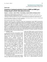
FIGURE 1.3. Axial CT scans of three vertebrae. (A) Scan of a T11 vertebra
demonstrates the sagittal configuration (straight posterior to anterior) of the
pedicle with respect to the vertebral body. The line demonstrates the general
tract that a needle would take during vertebroplasty by means of a transpedic-
ular approach. In the scan of an L5 vertebra (B), the transpedicular approach
(black line) is nearly 45° away from the sagittal plane. In the scan at T1 (C),
the transpedicular angle with the sagittal plane (black line) approaches 45°,
simiar to the angle found in the lowest lumbar vertebra.
A
B
the pedicles relative to the vertebral body changes as does their size.
From T4 to T12 the pedicles have a relatively straight sagittal (anterior-
to-posterior) orientation (Figure 1.3A). In the lumbar spine from L1 to
L4 there is a slow but progressive angle away from the sagittal orien-
tation. At L5 the angle is extreme and can approach 45° away from the
sagittal plane (Figure 1.3B). Progressive angulation also occurs from T4
toward the cervical region (Figure 1.3C). Therefore, both pedicle size
and angulation are important when one is planning a transpedicular
approach during intervention. Though the size of the pedicles varies
from region to region and from individual to individual, one can be
comfortable that a 13-gauge cannula (0.095 in., outside diameter) will
fit through essentially all adult pedicles from T4 to L5. In most indi-
viduals a 10- to 11-gauge cannula (0.134–0.120 in., outside diameter)
will safely pass through pedicles from T12 to L5.
When the size of the pedicle (or its absence in neoplastic disease)
precludes a transpedicular approach, a parapedicular route may be
necessary. This route takes the entry device along the lateral margin
of the pedicle and above the tranverse process. In the thoracic spine,
this trajectory is generally along the junction of the rib with the adja-
cent transverse process and vertebral body (Figure 1.4). The articula-
tion of the rib and vertebral body forms the costovertebral joint. The
costotransverse joint is the junction of the rib and transverse process,
with the intervening space filled with the costotransverse ligament. The
parapedicular needle entry point will be along the lateral and poste-
rior vertebral border in the paraspinal soft tissues. The paraspinus
Physical Components 5
FIGURE 1.3. Continued.
C
space is filled with fatty tissue and venous structures. Venous bleed-
ing is common here, but this is usually self-limiting as long as no co-
agulopathy exists. Occasionally, the posterior costophrenic sulcus con-
tains lung that bulges beyond the border of the rib, making
pneumothorax also possible.
The bones of the vertebra make up part of the central skeleton, in-
side of which the elements of the blood are made. This occurs in the
intertrabecular (marrow) space. The venous system connects to this
marrow space (Figure 1.5). This connection provides one of the main
avenues for cement leakage during vertebroplasty or kyphoplasty. The
venous route most important for potential leakage is through the pos-
terior vertebral wall, communicating with the veins in the epidural
space. Leakage into this location can create compression of the cord or
nerve roots. Venous leak anterior or laterally can result in cement mi-
gration into central veins carrying blood to the lungs (resulting in pul-
monary emboli).
6 Chapter 1 Spine Anatomy
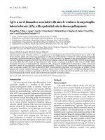
FIGURE 1.4. The parapedicular approach. (A) In this lateral view, notice that
the needle enters above the transverse process. (B) Needle placement position
for a parapedicular approach in vertebroplasty.
A
B
Physical Components 7
A
B
FIGURE 1.5. (A) The venous communications typical in a vertebra: AEVP, an-
terior external venous plexus; IVV, intervertebral vein; ARV, anterior radicu-
lar vein; PRV, posterior radicular vein; PIVP, posterior internal venous plexus;
PEVP, posterior external venous plexus; BVV, basivertebral vein. (B) Axial CT
scan demonstrating the posterior wall opening (black arrows) that allows the
major veins of the interior of the vertebra (BVV, basivertebral vein) to com-
municate with epidural veins.
Intervertebral Discs and Joints
The intervertebral discs and joints interface with the various vertebrae
in the spine. Together with the ligamentous attachments, these elements
allow the vertebrae to move through bending and rotation. However,
these discs and joints wear and may be the source of pain caused by
degeneration. The image-guided interventionist must deal with these
structures during discography, percutaneous discectomy, intradiscal
electrothermal therapy, facet blocks, and dorsal ramus neurolysis.
The intervertebral discs are composed of an outer ring of fibrocarti-
lage called the annulus fibrosis (Figure 1.6A,B). The annulus is attached
to the cartilaginous endplates of the vertebrae and constrains the inner
disc core called the nucleus pulposus. The annulus is thickest anteriorly.
It is thin posteriorly, which coincides with the area most commonly as-
sociated with annular tears and disc herniations. The outer annular
fibers, which are more densely packed, are referred to as Sharpey’s fibers.
The nucleus pulposus is made of cells that are notochordal remnants. It
is composed of collagen fibrils that are embedded in a proteoglycan ma-
trix that contains water. With aging and degeneration, water is lost and
the nucleus becomes progressively fibrotic and smaller.
Because of the spine curvature (Figure 1.1), the angle of the plane of
the disc between the vertebral endplates is variable through the spine.
This variation requires different imaging angulation to enter the disc
without obstruction by the adjacent vertebral margins. Appropriate im-
aging angulation is necessary for accurate needle placement in discog-
raphy and percutaneous disc therapy.
The apophyseal or facet joints are paired joints between the poste-
rior elements of two adjacent vertebrae. They are curved joints that are
oriented obliquely to the sagittal plane (Figure 1.6C). The joints are
asymmetric in about 30% of the population.
9
Each joint consists of an
articular process from each of the adjacent vertebra. The joint has a
synovial lining with a fibrous capsule (Figure 1.6A,B). The nerve sup-
ply is from the medial division of the dorsal ramus of the spinal nerve
that reaches the joint from the nerve above and below the joint on the
ipsilateral side (Figure 1.7A). The joint is believed to be a source of non-
radiating axial pain that is typically aggravated by hyperextension and
rest. Because the joint is curved, image guidance can be confusing and
entry into the joint may be difficult, particularly when there is degen-
erative disease. A small synovial recess along the superior and inferior
margins of the joint will allow access without passing through the
curved bone margins. Facet blocks are used for diagnostic confirma-
tion of the pain source. As they rarely have prolonged therapeutic ben-
efit, neurolysis of the joint nerve supply with chemical or radiofre-
quency (RF) ablation is most often used for long-term pain control.
8 Chapter 1 Spine Anatomy
F
IGURE 1.6. The intervertebral disc. (A) Lateral drawing depicting the disc com-
ponents and their association with the adjacent hyaline cartilaginous endplates.
(B) Axial drawing demonstrating that the annulus fibrosus is thickest anteri-
orly. The capsule and lining of the facet joint also are shown. (C) Axial CT scan
showing the complex configuration of the facet joints (black arrows).
Physical Components 9
A
B
C
10 Chapter 1 Spine Anatomy
FIGURE 1.7. (A) Axial drawing of the nerve exiting the neural foramina of a lum-
bar vertebra and giving off the posterior ramus. A medial branch of this nerve
will supply the capsule of the facet joint. These innervations arise from medial
branches from both above and below each joint. The gray and white rami com-
municantes connect the autonomic ganglia with the anterior division of the
spinal nerves. (B) Axial MR scan showing the neural foramina (white arrows)
of a lumbar vertebra containing the dorsal root ganglia (white arrowhead).
A
B