logic khả trình pdf
Bạn đang xem bản rút gọn của tài liệu. Xem và tải ngay bản đầy đủ của tài liệu tại đây (4.29 MB, 165 trang )
January 2006
1Verilog Digital System Design
Copyright Z. Navabi, 2006
Verilog Digital System Design
Verilog Digital System Design
Z. Navabi, McGraw-Hill, 2005
Z. Navabi, McGraw-Hill, 2005
Chapter 4
Chapter 4
Combinational Circuit
Combinational Circuit
Description
Description
Prepared by :
Prepared by :
Homa Alemzadeh - Nima Tayebi
Homa Alemzadeh - Nima Tayebi
January 2006
2Verilog Digital System Design
Copyright Z. Navabi, 2006
4.1 Module Wires
4.1 Module Wires
4.1.1 Ports
4.1.1 Ports
4.1.2 Interconnections
4.1.2 Interconnections
4.1.3 Wire values and timing
4.1.3 Wire values and timing
4.1.4 A simple testbench
4.1.4 A simple testbench
4.2 Gate Level Logic
4.2 Gate Level Logic
4.2.1 Gate primitives
4.2.1 Gate primitives
4.2.2 User defined primitives
4.2.2 User defined primitives
4.2.3 Delay formats
4.2.3 Delay formats
4.2.4 Module parameters
4.2.4 Module parameters
Combinational Circuit
Combinational Circuit
Description
Description
January 2006
3Verilog Digital System Design
Copyright Z. Navabi, 2006
4.3 Hierarchical Structures
4.3 Hierarchical Structures
4.3.1 Simple hierarchies
4.3.1 Simple hierarchies
4.3.2 Vector declarations
4.3.2 Vector declarations
4.3.3 Iterative structures
4.3.3 Iterative structures
4.3.4 Module path delay
4.3.4 Module path delay
4.4 Describing Expressions with Assign Statements
4.4 Describing Expressions with Assign Statements
4.4.1 Bitwise operators
4.4.1 Bitwise operators
4.4.2 Concatenation operators
4.4.2 Concatenation operators
4.4.3 Vector operations
4.4.3 Vector operations
4.4.4 Conditional operation
4.4.4 Conditional operation
4.4.5 Arithmetic expressions in assignments
4.4.5 Arithmetic expressions in assignments
4.4.6 Functions in expressions
4.4.6 Functions in expressions
4.4.7 Bus structures
4.4.7 Bus structures
4.4.8 Net declaration assignment
4.4.8 Net declaration assignment
Combinational Circuit
Combinational Circuit
Description
Description
January 2006
4Verilog Digital System Design
Copyright Z. Navabi, 2006
4.5 Behavioral Combinational Descriptions
4.5 Behavioral Combinational Descriptions
4.5.1 Simple procedural blocks
4.5.1 Simple procedural blocks
4.5.2 Timing control
4.5.2 Timing control
4.5.3 Intra-assignment delay
4.5.3 Intra-assignment delay
4.5.4 Blocking and nonblocking assignments
4.5.4 Blocking and nonblocking assignments
4.5.5 Procedural if-else
4.5.5 Procedural if-else
4.5.6 Procedural case statement
4.5.6 Procedural case statement
4.5.7 Procedural for statement
4.5.7 Procedural for statement
4.5.8 Procedural while loop
4.5.8 Procedural while loop
4.5.9 A multilevel description
4.5.9 A multilevel description
Combinational Circuit
Combinational Circuit
Description
Description
January 2006
5Verilog Digital System Design
Copyright Z. Navabi, 2006
4.6 Combinational Synthesis
4.6 Combinational Synthesis
4.6.1 Gate level synthesis
4.6.1 Gate level synthesis
4.6.2 Synthesizing continuous assignments
4.6.2 Synthesizing continuous assignments
4.6.3 Behavioral synthesis
4.6.3 Behavioral synthesis
4.6.4 Mixed synthesis
4.6.4 Mixed synthesis
4.7 Summary
4.7 Summary
Combinational Circuit
Combinational Circuit
Description
Description
January 2006
6Verilog Digital System Design
Copyright Z. Navabi, 2006
Module Wires
Module Wires
Wires or
Wires or
net
net
s are used for interconnection of substructures together,
s are used for interconnection of substructures together,
and interconnection of module ports to appropriate ports of a
and interconnection of module ports to appropriate ports of a
module’s substructures.
module’s substructures.
By default module ports are wires (
By default module ports are wires (
net
net
).
).
Wires have delays, can take ant of the four values (
Wires have delays, can take ant of the four values (
0
0
,
,
1
1
,
,
Z
Z
and
and
X
X
).
).
January 2006
7Verilog Digital System Design
Copyright Z. Navabi, 2006
Module Wires
Module Wires
Module
Module
Wires
Wires
Ports
Ports
Interconnections
Interconnections
Wire Values
Wire Values
and Timing
and Timing
A Simple
A Simple
Testbench
Testbench
January 2006
8Verilog Digital System Design
Copyright Z. Navabi, 2006
Ports
Ports
Module
Module
Wires
Wires
Ports
Ports
Interconnections
Interconnections
Wire Values
Wire Values
and Timing
and Timing
A Simple
A Simple
Testbench
Testbench
Ports
Ports
January 2006
9Verilog Digital System Design
Copyright Z. Navabi, 2006
Ports
Ports
Ports are allowed to be defined as
Ports are allowed to be defined as
input
input
,
,
output
output
or
or
inout
inout
.
.
An
An
input
input
port is always a
port is always a
net
net
and can only be read.
and can only be read.
An
An
output
output
is a
is a
net
net
by default, and can be declared as a
by default, and can be declared as a
reg
reg
if it is to be
if it is to be
assigned a value inside a procedural block.
assigned a value inside a procedural block.
An
An
inout
inout
is a bidirectional port that can be written into or read from.
is a bidirectional port that can be written into or read from.
An
An
inout
inout
port is always a
port is always a
net
net
.
.
January 2006
10Verilog Digital System Design
Copyright Z. Navabi, 2006
Ports
Ports
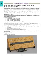
A Simple Module
A Simple Module
`timescale
`timescale
1ns/100ps
1ns/100ps
module
module
Anding (
Anding (
input
input
a, b,
a, b,
output
output
y);
y);
and
and
(y, a, b);
(y, a, b);
endmodule
endmodule
Ports
Ports
January 2006
11Verilog Digital System Design
Copyright Z. Navabi, 2006
Ports
Ports
The symbol of
The symbol of
output ports
output ports
The symbol of
The symbol of
input ports
input ports
Multiplexer using Tri-state buffers
Multiplexer using Tri-state buffers
January 2006
12Verilog Digital System Design
Copyright Z. Navabi, 2006
Interconnections
Interconnections
Module
Module
Wires
Wires
Ports
Ports
Interconnections
Interconnections
Wire Values
Wire Values
and Timing
and Timing
A Simple
A Simple
Testbench
Testbench
Interconnections
Interconnections
January 2006
13Verilog Digital System Design
Copyright Z. Navabi, 2006
Interconnections
Interconnections
A Simple Module
A Simple Module
`timescale
`timescale
1ns/100ps
1ns/100ps
module
module
Anding (
Anding (
input
input
a, b,
a, b,
output
output
y);
y);
and
and
(y, a, b);
(y, a, b);
endmodule
endmodule
Values put into the
Values put into the
a
a
and
and
b
b
inputs of
inputs of
Anding
Anding
are carried
are carried
through these wires to the
through these wires to the
inputs of and.
inputs of and.
The and primitive generates
The and primitive generates
its output, which is carried
its output, which is carried
through the
through the
y
y
net to the
net to the
output of
output of
Anding
Anding
.
.
January 2006
14Verilog Digital System Design
Copyright Z. Navabi, 2006
Wire Values and Timing
Wire Values and Timing
Module
Module
Wires
Wires
Ports
Ports
Interconnections
Interconnections
Wire Values
Wire Values
and Timing
and Timing
A Simple
A Simple
Testbench
Testbench
Wire Values
Wire Values
and Timing
and Timing
January 2006
15Verilog Digital System Design
Copyright Z. Navabi, 2006
Wire Values and Timing
Wire Values and Timing
A
A
net
net
used for a module port or an internal interconnection can take
used for a module port or an internal interconnection can take
any of the four Verilog logic values, i.e.,
any of the four Verilog logic values, i.e.,
0
0
,
,
1
1
,
,
Z
Z
, and
, and
X
X
.
.
Such a value assigned to a
Such a value assigned to a
net
net
can have a delay, which may be specified
can have a delay, which may be specified
by the assignment to the
by the assignment to the
net
net
or as part of its declaration.
or as part of its declaration.
Multiple simultaneous assignments to a
Multiple simultaneous assignments to a
net
net
, or driving a
, or driving a
net
net
by
by
multiple sources is legal and the result is defined by the type of the
multiple sources is legal and the result is defined by the type of the
net
net
.
.
January 2006
16Verilog Digital System Design
Copyright Z. Navabi, 2006
Wire Values and Timing
Wire Values and Timing
Multiplexer using Tri-state buffers
Multiplexer using Tri-state buffers
Multiplexer built
Multiplexer built
by tri-state buffers
by tri-state buffers
Tri-state buffers
Tri-state buffers
January 2006
17Verilog Digital System Design
Copyright Z. Navabi, 2006
Wire Values and Timing
Wire Values and Timing
Verilog for a Multiplexer with Tri-state Buffers
Verilog for a Multiplexer with Tri-state Buffers
`timescale
`timescale
1ns/100ps
1ns/100ps
module
module
TriMux (
TriMux (
input
input
i0, i1, sel,
i0, i1, sel,
output
output
y);
y);
wire
wire
sel_ ;
sel_ ;
not
not
#5 g0 (sel_, sel);
#5 g0 (sel_, sel);
bufif1
bufif1
#4
#4
g1 (y, i0, sel_),
g1 (y, i0, sel_),
g2 (y, i1, sel );
g2 (y, i1, sel );
endmodule
endmodule
Instance Name
Instance Name
Optional for primitive
Optional for primitive
instantiations
instantiations
A Delay of 5ns
A Delay of 5ns
for the not gate
for the not gate
Two instances of
Two instances of
bufif1
bufif1
are combined into one
are combined into one
gate instantiation
gate instantiation
construct
construct
January 2006
18Verilog Digital System Design
Copyright Z. Navabi, 2006
Wire Values and Timing
Wire Values and Timing
Simulation Results of buff1
Simulation Results of buff1
Because of the delay
Because of the delay
of the
of the
not
not
gate, this X
gate, this X
value remains on
value remains on
y
y
for
for
5 ns
5 ns
.
.
At time 45 ns
At time 45 ns
sel
sel
becomes 0.
becomes 0.
Because of this change, after a
Because of this change, after a
4ns delay, neither
4ns delay, neither
g1
g1
nor
nor
g2
g2
conduct, causing a Z (high
conduct, causing a Z (high
impedance) to appear on
impedance) to appear on
y
y
for a
for a
period of 5 ns (inverter delay).
period of 5 ns (inverter delay).
Simulation Results of
Simulation Results of
bufif1
bufif1
At time 34 ns, both
At time 34 ns, both
g1
g1
and
and
g2
g2
conduct.
conduct.
g1
g1
is still
is still
conducting because it
conducting because it
takes the
takes the
not
not
gate 5 ns to
gate 5 ns to
change the value of
change the value of
sel_
sel_
and
and
bufif1
bufif1
an extra 4 ns to
an extra 4 ns to
stop
stop
g1
g1
from conducting.
from conducting.
This causes the value X to
This causes the value X to
appear on
appear on
y
y
.
.
January 2006
19Verilog Digital System Design
Copyright Z. Navabi, 2006
A Simple Testbench
A Simple Testbench
Module
Module
Wires
Wires
Ports
Ports
Interconnections
Interconnections
Wire Values
Wire Values
and Timing
and Timing
A Simple
A Simple
Testbench
Testbench
A Simple
A Simple
Testbench
Testbench
January 2006
20Verilog Digital System Design
Copyright Z. Navabi, 2006
`timescale
`timescale
1ns/100ps
1ns/100ps
module
module
TriMuxTest;
TriMuxTest;
reg
reg
i0=0, i1=0, s=0;
i0=0, i1=0, s=0;
wire
wire
y;
y;
TriMux MUT (i0, i1, s, y);
TriMux MUT (i0, i1, s, y);
initial
initial
begin
begin
#15 i1=1’b1;
#15 i1=1’b1;
#15 s=1’b1;
#15 s=1’b1;
#15 s=1’b0;
#15 s=1’b0;
#15 i0=1’b1;
#15 i0=1’b1;
#15 i0=1’b0;
#15 i0=1’b0;
#15
#15
$finish
$finish
;
;
end
end
endmodule
endmodule
A Simple Testbench
A Simple Testbench
A Testbench for TriMux
A Testbench for TriMux
The initial statement is
The initial statement is
a procedural construct
a procedural construct
and uses delay control
and uses delay control
statements to delay the
statements to delay the
program flow in this
program flow in this
procedural block
procedural block
.
.
The delay before
The delay before
$finish
$finish
allows the last input change
allows the last input change
to have a chance to affect
to have a chance to affect
the circuit output
the circuit output
.
.
Because
Because
i0
i0
,
,
i1
i1
, and
, and
s
s
must be assigned
must be assigned
values in this testbench, they are
values in this testbench, they are
declared as reg and initialized to 0
declared as reg and initialized to 0
.
.
January 2006
21Verilog Digital System Design
Copyright Z. Navabi, 2006
Gate Level Logic
Gate Level Logic
Gate Level
Gate Level
Logic
Logic
Gate
Gate
Primitives
Primitives
User Defined
User Defined
Primitives
Primitives
Delay
Delay
Formats
Formats
Module
Module
Parameters
Parameters
January 2006
22Verilog Digital System Design
Copyright Z. Navabi, 2006
Gate Primitives
Gate Primitives
Gate Level
Gate Level
Logic
Logic
Gate
Gate
Primitives
Primitives
User Defined
User Defined
Primitives
Primitives
Delay
Delay
Formats
Formats
Module
Module
Parameters
Parameters
Gate
Gate
Primitives
Primitives
January 2006
23Verilog Digital System Design
Copyright Z. Navabi, 2006
Gate Primitives
Gate Primitives
Basic Gate Primitives
Basic Gate Primitives
January 2006
24Verilog Digital System Design
Copyright Z. Navabi, 2006
Gate Primitives
Gate Primitives
Gates categorized as
Gates categorized as
n_input
n_input
gates are
gates are
and
and
,
,
nand
nand
,
,
or
or
,
,
nor
nor
,
,
xor
xor
, and
, and
xnor
xnor
.
.
An
An
n_input
n_input
gate has one output, which is its left-most argument, and
gate has one output, which is its left-most argument, and
can have any number of inputs.
can have any number of inputs.
nand
nand
#(3, 5) gate1 (w, i1, i2, i3, i4);
#(3, 5) gate1 (w, i1, i2, i3, i4);
A 4-input nand
A 4-input nand
tPLH (low to high
tPLH (low to high
propagation) and
propagation) and
tPHL (high to low
tPHL (high to low
propagation) times are
propagation) times are
3 and 5, respectively
3 and 5, respectively
.
.
January 2006
25Verilog Digital System Design
Copyright Z. Navabi, 2006
Gate Primitives
Gate Primitives
Majority Circuit
Majority Circuit
A majority circuit
A majority circuit
(
(
maj3
maj3
) with
) with
a
a
,
,
b
b
,
,
c
c
input and
input and
y
y
output.
output.
For connecting and
For connecting and
gate outputs to the
gate outputs to the
output or gate,
output or gate,
intermediate wires
intermediate wires
im1
im1
,
,
im2
im2
, and
, and
im3
im3
are used.
are used.