An Analysis of Geometric Modeling in Database Systems docx
Bạn đang xem bản rút gọn của tài liệu. Xem và tải ngay bản đầy đủ của tài liệu tại đây (2.81 MB, 45 trang )
An Analysis of Geometric Modeling in Database Systems
ALFONS KEMPER and MECHTILD WALLRATH
Universitat Karlsruhe, Institut fiir Znformatik ZZ, D-7500 Karlsruhe, West Germany
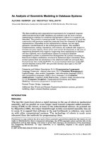
The data-modeling and computational requirements for integrated computer
aided manufacturing (CAM) databases are analyzed, and the most common
representation schemes for modeling solid geometric objects in a computer are
described. The primitive instancing model, the boundary representation, and the
constructive solid geometry model are presented from the viewpoint of database
representation. Depending on the representation scheme, one can apply
geometric transformations to the stored geometric objects. The standard
transformations, scaling, translation, and rotation, are outlined with respect to
the data structure aspects. Some of the more recent developments in the area of
engineering databases with regard to supporting these representation schemes
are then explored, and a classification scheme for technical database
management systems is presented that distinguishes the systems according to
their level of object orientation: structural or behavioral object orientation. First,
several systems that are extensions to the relational model are surveyed, then
the functional data model DAPLEX, the nonnormalized relational model NF’,
and the database system R2D2 that provides abstract data types in the NF’
model are described.
Categories and Subject Descriptors: D.3.3 [Programming Languages]:
Language Constructs-abstract data types; H.2.1 [Database Management]:
Logical Design-data models; Languages-data description languages (DDL);
data manipulation languages (DML); query languages; J.6 [Computer
Applications]: Computer-Aided Engineering-computer-aided manufacturing;
1.1.3.5 [Computer Graphics]: Computational Geometry and Object
Modeling-hierarchy and geometric transformation
General Terms: Design, Languages
Additional Key Words and Phrases: Engineering database systems, geometric
modeling, object-oriented database systems
INTRODUCTION
Motivation
The last few years have shown a rapid increase in the use of robots in mechanical
assembly, and we predict an even larger trend toward computer-aided manufac-
turing (CAM) in the future, at least in the industrialized nations. As pointed out
by Requicha [ 19801, the major breakthrough in fully automated assembly has yet
to come. It is argued that software is the real bottleneck in robotics, very much
as with other computerized systems. The technology of robots is much more
advanced than the methods for programming them.
Permission to copy without fee all or part of this material is granted provided that the copies are not
made or distributed for direct commercial advantage, the ACM copyright notice and the title of the
publication and its date appear, and notice is given that copying is by permission of the Association
for Computing Machinery. To copy otherwise, or to republish, requires a fee and/or specific
permission.
0 1987 ACM 0360-0300/87/0300-0047 $1.50
ACM Computing Surveys, Vol. 19, No. 1, March 1987
48
l
A. Kemper and M. Wallrath
CONTENTS
INTRODUCTION
Motivation
FOCUS
1. REPRESENTATION SCHEMES
1.1 Primitive Instancing
1.2 Constructive Solid Geometry
1.3 Boundary Representation
2. GEOMETRIC TRANSFORMATIONS
2.1 Translation
2.2 Homogeneous Coordinates
2.3 Scaling
2.4 Rotation
2.5 Simulation of Assembly Operations
as Geometric Transformations
3. SURVEY OF PROPOSALS FOR
ENGINEERING DATABASES
3.1 The (Pure) Relational Database Systems
3.2 Object Orientation: A Classification Scheme
for Engineering Databases
3.3 QUEL as a Datatype
3.4 ADT-INGRES
3.5 GEM
3.6 The Complex Object Data Model:
An Extension to System R
3.7 The Functional Data Model
3.8 The NFa Data Model
3.9 R2D2: Relational Robotics Database System
with Extensible Data Types
4. CONCLUSIONS
ACKNOWLEDGMENTS
REFERENCES
BIBLIOGRAPHY
The traditional approach to robot programming consists of manually leading
the robot through all the assembly operations. This method could be called
“programming by example.” Every robot operation that is required for the
assembly process is executed once and stored for repetitive execution during the
actual assembly operation. The main disadvantage of this approach is that it ties
a robot to the assembly environment during the development phase of the
application.
A second approach, consisting of programming the robotic application off line
[Wesley 19801, is at a much higher programming level than the traditional
programming-by-example method. It is still in its infancy and is an active
research issue. This approach frees the robot, as well as the workspace of
the robot, from the development phase of the assembly process. The robot is
programmed in an assembly-oriented language, where a sample instruction
might be
mount cog wheel x on shaft y
This high-level assembly program has to be translated into a robot motion
program that specifies exactly where to grasp the cog wheel x and where the
shaft y is located in the workspace. Furthermore, a path has to be selected to get
to the position of the object x and back to object y without colliding with any
other fixtures in the workspace.
Because all these computations are performed off line, that is, the robot as
well as the workspace is simulated, we need a precise model of the robot and its
surrounding workspace in order to simulate the assembly operation. Figure 1 is
a schematic rendering of an off-line integrated robotics programming system
according to Wesley [ 19801 and Blume et al. [ 19831.
The central part of such an integrated robotics programming system forms a
comprehensive database that stores the so-called world model by describing the
physical and geometric properties of real objects. The physical data describe such
aspects as the material of which an object is composed and are entered via a
geometric design processor that allows the engineer to specify and manipulate
real-world objects interactively.
ACM Computing Surveys, Vol. 19, No. 1, March 1987
An Analysis
of
Geometric Modeling in Database Systems
An Analysis
of
Geometric Modeling in Database Systems
l l
49 49
Figure 1.
Integrated robotics data-
base system.
Figure 1 shows the two other main modules that interface to the world model
database:
(1) the robot emulator system;
(2) the compiler.
The robot emulator system is used to simulate existing robot motion programs
for validation purposes. This is especially important if the robots are used in
highly sensitive application areas, such as nuclear power plants, where any
undetected program error could lead to very dangerous situations.
The second module, the compiler, gets an assembly-directed program as input.
From the world model database the compiler deduces how to translate the
assembly-oriented commands into robot motions. Of course, the world model is
not a static database; rather, it is dynamic, that is, it is manipulated according
to robot operations. The real-world assembly process is simulated by manipulat-
ing the database accordingly.
Even though the world model database forms the central part of the integrated
robotics simulation system, it has traditionally received the least attention. All
known commercially available CAD/CAM systems for robotics are based on a
customized file system rather than a comprehensive database management sys-
tem. Their main disadvantage is that there is no generally accepted format to
which other modules can interface. To manipulate the data obtained by one
CAD/CAM module by
some
other module generally requires tedious conversion
of the data.
Why have database management systems not been employed? The answer to
this question is manyfold. (1) Today’s commercially available DBMSs, which are
designed for highly structured commercial database applications, do not ade-
quately support technical problem domains [Lockemann et al. 19851. (2) It is not
clear that we can achieve the
same
efficiency that is possible with a special-
purpose file structure with currently available general-purpose DBMSs. (3) The
CAD/CAM systems are usually designed and implemented by engineers who are
not necessarily database experts. Database experts have traditionally ignored
ACM Computing Surveys, Vol. 19, No. 1, March 1987
50 ’
A. Kemper and it!. Wallrath
technical problem domains. Only recently has there been a shift of research
activities within the database community toward engineering applications.
Focus
We first want to analyze the requirements imposed on database management
systems by computer-aided manufacturing applications. We begin by describing
the more important representation schemes for solid geometric objects as they
occur in the robotics world. This investigation is carried out primarily from a
database point of view rather than by presenting a rigorous mathematical
definition of the representation schemes. Section 2 describes the geometric
transformations that can be applied to solid objects stored in the world model
database. Section 3 presents a classification scheme for technical database
systems and reviews some of the more recent proposals for engineering databases
with respect to their suitability for integrated robotics databases. The first
systems that we survey are extensions to the relational model. Then we investi-
gate the functional data model DAPLEX as one representative of the object-
oriented approach. The NF2 model is a nonnormalized relational model that
allows nested relations. R2D2 (Relational Robotics Database System with Exten-
sible Data Types) is a database system that is based on the NF2 model and allows
the database user to define application-specific data types and operations. The
systems are described by defining a sample schema of some geometric represen-
tation model. Section 4 summarizes the main results of our investigation.
1. REPRESENTATION SCHEMES
Robots manipulate solid geometric objects. Thus the basis for any automated
assembly operation by robots is a way of storing information about geometric
objects in a computer. There are several quite different representation methods
for solid objects. Some of them are investigated in this section. We do not attempt
to give a formal or complete definition of all existing representation schemes for
three-dimensional solid objects. Rather, we restrict ourselves to outlining the
most important schemes. Only those aspects of importance to the design of
database support of the particular representation are described. A more theoret-
ical overview is provided by Requicha [ 19801.
There are three representation schemes for which database support is feasible
[ Maier 19851:
(1) primitive instancing;
(2) constructive solid geometry (CSG);
(3) boundary representation (BR) .
Our presentation is based primarily on the example geometric object of Figure 2,
a bracket with four holes that frequently occurs in assembly operations. Even
though this example object is a fairly simple one, it should suffice to demonstrate
the main characteristics of the three representation schemes.
1.1 Primitive Instancing
In this approach every geometric object is defined as a special instance of a
generic primitive object. In relational database terminology this means that one
would create a relation for every generic object type. The attributes of the relation
would correspond to the parameters that describe the geometric object. Each
geometric object would then be stored as a tuple of the relation corresponding to
the generic object class.
ACM Computing Surveys, Vol. 19, No. 1, March 1987
An Analysis
of
Geometric Modeling in Database Systems
l
51
Figure2. Bracket with four
holes.
An example of a generic object class might be brackets with holes, as shown in
Figure 2.
Now let us consider a generic record type that would describe the object class
bracket with a variable number of holes. The record type would be defined as
follows:
generic type BRACKET (#holes:integer)
length: real
width: real
height: real
material: {iron, copper, . . .]
. . .
HOLES : array [ 1 . . #holes] of
record
diameter: real
location: array [l . .3] of real
end record
end generic type BRACKET
A particular object of type BRACKET with four holes is instantiated as follows:
create BRACKET(4)
The reader will note that this is a very simple representation for a number of
well-known and highly structured assembly objects, such as brackets, nuts, cog
wheels, and shafts. As is pointed out in the literature [Voelcker and Requicha
19771, however, the majority of mechanical objects are produced only in relatively
small quantities, on the order of 500, say. This means that the number of
instances of a particular object class is fairly small, whereas there is usually a
large number of different generic object classes. The primitive instancing ap-
proach is not useful in such applications since it requires the specification of a
generic record type for each different object class. In database terms this means
that we would have to create an abundance of different relations, each consisting
of only a small number of tuples. For this reason this approach is not always
usable in a general-purpose CAM system.
1.2 Constructive Solid Geometry
Together with the boundary representation, the CSG scheme is the most widely
used representation in existing CAD/CAM systems. It is possible to transform a
CSG representation to a BR representation automatically. Many existing systems
ACM Computing Surveys, Vol. 19, No. 1, March 1987
52
l
A. Kemper and M. Wallrath
Geometric
Ll
Input
System
User
Geometric Models
programs
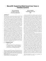
Figure 3. Typical architecture of a geometric modeling system.
[Requicha 19801 are organized as shown in Figure 3. The input to the geometric
modeling system is usually via the CSG representation, which is much easier for
the user, that is, the engineer, to handle than is the boundary representation.
Internally, the CSG representation is automatically transformed into the bound-
ary representation.
The CSG scheme is a volumetric representation of geometric objects, in which
an object is described as a composition of a few primitive objects. The composition
is achieved via motional or combinatorial operators. Example operators are the
(regularized) union, intersection, and difference of two solid objects. Motional
operators are, for example, “rotate” and “scale”. The description of a geometric
object in CSG format is a tree defined by the following context-free grammar:
<mechanical part> ::= <object>
Cobj ect> ::= <primitive> I
<object> <motion op> <motion argument>1
<object> <set operator> <object>
<primitive> ::= cube I cylinder I cone I . . .
<motion op>
::= rotate
I
ecale I . . .
<set operator> ::= union
I
intersection
I
difference
I . . .
In Figure 4 we show a CSG tree for our example object “bracket with 4 holes.”
In the CSG tree each nonterminal node represents an operation, either a rigid
motion or a combinatorial (set) operator. Terminal nodes either represent a
motion argument or a primitive object. Each primitive object is described by its
parameters, such as length, width, and height, as well as its relative position.
In our example we have only two primitive objects: cuboid and cylinder. A
cuboid is defined by its length, width, and height. A cylinder is defined by its
radius and length.
We notice that, in contrast to the primitive instancing scheme, the CSG
representation requires only a few primitive objects. Therefore the CSG tree of
complex objects can become very deep, which might lead to inefficient data
retrieval if there is no suitable data access support.
ACM Computing Surveys, Vol. 19, No. 1, March 1987
An Analysis of Geometric Modeling in Database Systems
l
53
. lO
. ll
cuboid
cylinder
Figure 4. CSG tree of the bracket.
1.3 Boundary Representation
In this representation scheme a solid object is segmented into its nonoverlapping
faces. Each face in turn is modeled by its bounding edges and vertices. Again we
present the representation of our bracket in Figure 5.
From a database point of view we note that this representation scheme consists
of different abstraction levels, that is, faces, edges, and vertices. In contrast to
the CSG scheme, the depth of the tree is constant, that is, 3. A more complex
solid object just leads to more nodes in the tree without increasing the depth.
The lowest level of the tree stores the metric information, that is, three-tuples
(Xi, yip Zi) for vertex Ui, for i in 11, . . . ,
m). The second level of the tree stores the
edges as combinations of vertices. Edge ei is represented by the tuple (Uil, Viz),
where i in (1, . . . , n). On the topmost level of the tree each node describes a
variable number of edges which represent the boundaries of one face of the rigid
object.
2. GEOMETRIC TRANSFORMATIONS
The two most important representation models for rigid solids are the construc-
tive solid geometry model (CSG) and the boundary representation (BR). To
display the edges of a three-dimensional solid on a computer display, the boundary
representation is much easier to handle. Many commercially available
ACM Computing Surveys, Vol. 19, No. 1, March 1987
54
l
A. Kemper and M. Wallrath
r, . . . FACES
% e,
e, . . .
EDGES
“I “1 “8 “4 “I “8 “7 “8 “1
VI0 . . .
VERTICES
Figure 5. Boundary representation of the bracket.
three-dimensional modelers employ the CSG method for inputting an object, but
can automatically transform the representation to BR format, as was shown in
Figure 3.
In this section we give the reader a brief introduction to the area of computer
geometry. Unfortunately this presentation does not allow us to give a detailed
treatment of this problem domain. We refer the reader who wants more details
to the book by Foley and van Dam [1983]. In this section we merely outline the
computational requirements imposed on the geometric modeling system by
geometric transformations.
A graphical display of a geometric object, in this case a cuboid, is shown in
Figure 6. Except for references to faces and edges, the only data that are stored
in the boundary representation are vertices in the three-dimensional space, that
is, vectors of the form (x, y, z). To uniquely describe the cuboid, one has to store
the eight vertices ul, . . . ,
us. The corresponding boundary representation of this
cuboid is depicted in Figure 7.
In order to be able to view an object from different perspectives (angles) and
to zoom in and out on the particular object, one can apply three geometric
ACM Computing Surveys, Vol. 19, No. 1, March 1987
An Analysis
of
Geometric Modeling in Database Systems
l 55
Figure6. Projection of a cuboid on a
display.
v, -e,- v2
X
*: . . . . . . . .
@
* *
*.a*
*.*.
. .
FACES
eM e, es e, EDGES
VI
V2
Vs
V4 VI Vll
V1
v8 VERTICES
Figure 7. Boundary representation of the cuboid.
transformations to the object stored in BR representation:
l translation;
l rotation;
0 scaling.
We briefly explain each of these transformations in turn.
2.1 Translation
Translation corresponds to moving the graphical object within the three-
dimensional coordinate system relative to the origin without altering the object’s
orientation. This is achieved by rotations, which are explained later. A translation
ACM Computing Surveys, Vol. 19, No. 1, March 1987
56 .
A. Kemper and M, Wallrath
is defined by the translation vector T = (OX, Q, D,). A single vertex is translated
by adding the translation vector to the vector representing the vertex in the
three-dimensional system:
ui = (Xi9 Yi, zi),
T = (D,, Dy, DA
T(ui) I= Ui + T = (xi + D,, yi + Dy, Zi + D,).
To translate a geometric object represented in boundary representation re-
quires translating all vertices of the object that are stored in the BR schema.
Thus, for the example of the cuboid, one would have to carry out the following
computation:
fi; all ui in {uI, . . . , us] do
ui := vi+ T;
2.2 Homogeneous Coordinates
The other two transformation operations, that is, scaling and rotation, can be
defined naturally as multiplications of the vertex (vector) with a corresponding
transformation matrix, as we show below. In order to be able to combine different
transformations of the same object, for example, rotation and translation, we
would like to also represent translation as a matrix multiplication. Then we
would be able to combine different transformation matrices by multiplying them.
In order to represent the translation also as a matrix multiplication, the
concept of homogeneous coordinates has to be employed, as is done in many
graphics packages [Foley and van Dam 19831. This concept requires a vertex to
be stored as a four-element, rather than a three-element, vector. Then vertex Ui
is represented as
vi = [Xi,
Yi9 zi, 11.
Now the translation matrix T looks as follows:
1 1 0 0 0 0 0 0
T= T=
[ [
0 0 100 100
0 0 0 1 0 0 1 0
1 1
* *
D, D, Dy D, 1 Dy D, 1
The translation of the vertex Ui is then defined as
10 00
T(ui) = [xi, yiy Zi, 11 *
0 100
[ 1
o o 1 o
= [xi + Dx, yi + Dy, Zi + Dz, 11.
D, Dy Dz 1
Translation of the cuboid would then result in the following program fragment:
f& all ui in (u,, . . . , us] do
Ui:= ui * T;
2.3 Scaling
An important concept in viewing geometric objects on a computer display is
varying the size in form of scaling (or stretching). Vertices (as endpoints of
vectors) can be scaled by S, along the x-axis, S, along the y-axis, and S, along
ACM Computing Surveys, Vol. 19, No. 1, March 1987
An Analysis of Geometric Modeling in Database Systems
l
57
Y4
. . . . . . . . . . . . . . j c+(1,3)
~ :
s+,q
I
I
I
Figure 8.
Scaling of a two-dimensional object.
I
I
I
I
I
I
I
I
I
-
X
the z-axis, according to the scaling matrix S as follows:
s, 0 0 0
S(Ui) = [Xi, yiy Zi, l] *
0 s, 0 0
‘[ I
o o s o
= [Sx * Xi, Sy * .Yi, S* * zi9 l]-
0 0 d 1
Scaling of a two-dimensional object is shown in Figure 8. Scaling of a geometric
object is carried out by scaling each surrounding edge of the object representation
in BR format, which is equivalent to scaling each vertex of the BR representation.
Thus the following program would scale the cuboid of Figure 2:
foralluiin(~l, ,us)do
Ui := Ui * S;
where
ui = [Xi,
Yit
zit
ll,
s= [
s, 0
0 0
0 s,
0 0
0 0
s, 0 ’
0 0
0 1
I
and the centered asterisk (*) corresponds to matrix multiplication.
2.4 Rotation
Rotations are used to change the orientation of geometric objects in the three-
dimensional space. This way one can provide a view of the objects from all
different angles. Graphically, rotation of a cuboid is shown in Figure 9.
In three dimensions we have to distinguish three kinds of rotations:
l
rotation about the z-axis;
l
rotation about the x-axis;
l
rotation about the y-axis.
Here we show only briefly the definition of rotation about the z-axis. The
interested reader is referred for more detail to Foley and van Dam [ 19831.
ACM Computing Surveys, Vol. 19, No. 1, March 1987
58 l
A. Kemper and M. Wallrath
Figure 9.
Rotation of the cuboid.
fjpJq+
A rotation about the z-axis is defined by the rotation angle a. Corresponding
to this angle the rotation matrix R,(a) is constructed as
The rotation of vertex Ui is then given as
r
cos a
sin 9 0 0’
[Xi, Yi9 zip
11 *
i
-sin @ cos @ 0 0
o o 1 o
0 0
0 1.
= [Xi *
COS
@ - yi * sin a’, Xi * sin
9 + yi *
COS
*, Zi, 11.
Rotation of a geometric object stored in boundary representation is carried out
analogously to scaling and translation; that is, each vertex has to be rotated. The
program fragment is shown below:
for all ui in (IJ~, . . . , ugJ do
Ui := Ui * R,(G);
2.5 Simulation of Assembly Operations as Geometric Transformations
As described in Figure
1,
the world model database forms the central part of a
robot programming system. One major task in such a system is to simulate off-
line robotics operations, for example, assembly operations of the form
mount cog wheel x on shaft y
The standard geometric transformations described above are the operations
used to model such an operation. We assume that object x (the cog wheel) exists
at some location in the world of this robot application, that is, it exists in the
world model database. The same holds true for object y, the shaft onto which x
has to be mounted. Simulating this assembly operation means, in terms of the
world model database, changing the location of object 3~. In our particular case
this is achieved (not regarding the problem of collision handling) by the following
(standard) geometric operations:
1. Translate by Ti
(pick up object x).
2. Rotate about the z-axis by R,(a).
3. Rotate about the x-axis by R,(8)
(rotate x).
4. Rotate about the y-axis by R,(r).
5. Translate again by T2
(mount object x on y).
ACM Computing Surveys, Vol. 19, No. 1, March 1987
An Analysis
of
Geometric Modeling in Database Systems
The following program fragment would achieve this transformation:
for all Vi in {VI,
~2, ~3, . . .)
do
begin
~i:=vi*
T1;
vi := vi *
R,(a);
v, := vi * R,(8);
LJ~ := vi *
Ry(I’);
v; := v, * T,;
end
l
59
This results.in altogether 5 * j matrix multiplications, where j is the number of
vertices used to describe object X. For example, if 8 vertices are used to model
the object, the above method would result in 40 multiplications. A much more
efficient way combines the transformation matrices T1, R,(a), R,(0), R,(r) into
one matrix M:
M := Tl * U-L(*) * (R,W * (R,(r) * Tz)))
for all vi in
{II,, ~2, ~3, . . .)
do
vi := vi * M;
This method results in 5 + j matrix multiplications; that is, for an object with
8 vertices, one needs 13 multiplications.
3. SURVEY OF PROPOSALS FOR ENGINEERING DATABASES
In this section we first sketch the relational database model for those readers
who are not familiar with databases. Then we introduce the notion of object
orientation in database systems, which is applied to characterize the engineering
database systems investigated in the remainder of this section.
3.1 The (Pure) Relational Database Systems
In the introduction to this paper we cited a few reasons why database management
systems have not been extensively used in technical applications. The main
reason is that the data-modeling capabilities of the traditional database systems
are insufficient for engineering applications. For example, in the relational
database model [Codd 19701 technical objects usually have to be decomposed
onto different relations. Let us illustrate this on a relational BR schema that is
ACM Computing Surveys, Vol. 19, No. 1, March 1987
60
l
A. Kemper and M. Wallrath
We notice that this representation is broken up into four different relations,
where the relat,ionship of the tuples of the various relations is achieved via user-
generated attribute va1ues.l This makes the model difficult to use by the database
user, that is, the engineer, in order to retrieve and manipulate the data because
it requires an intrinsic knowledge of the underlying schema definition. In order
to retrieve all the bounding vertices of the mechanical part “cuboid,” one could
formulate the following SQL [IBM 19811 or QUEL [Stonebraker et al. 19761
queries:
Zelec: Mech-Part.1D.X.Y.Z
iIon Mech~Part,FACES,EDCES,VERTICES
Fhern Mech-Part.FACES = FACES.ID
~4 FAcEs.EDGES =
EDGES.ID
ad EDGES. VERTICES = VERTICES. ID
@ Mech-Part.ID = ‘cuboidm
range 02 m &Z Mech-Part
range of
f
fe FACES
range Q$ e &g EDGES
rggg og v ie VERTICES
Ie&I&n (m.ID,v.X,v.Y,v.Z)
F&Ie m.FACES = f.ID
ggQ f.EDGES = e.ID
and e.VERTICES = v.ID
and m.ID = .cuboid.
These queries involve joining the four relations Mech-Part, FACES, EDGES,
and VERTICES. Adequately supporting such frequent join operations seems to
be the major issue in extending the (pure) relational model for engineering use
[Lorie 1982; Lorie and Plouffe 19831.
3.2 Object Orientation: A Classification Scheme for Engineering Databases
In summary one could state that the problems with traditional database manage-
ment systems stem from the fact that they do not allow the modeling of
engineering objects in a natural way-or at least they do not support the retrieval
and manipulation of such objects in a way that is familiar to engineers. In
particular, they do not handle technical objects as a whole database entity; rather,
they require a schema design that is imposed by the underlying data model but
does not necessarily constitute a natural mapping of technical objects on database
structures.
Object-oriented
database systems have been proposed by many authors as a
new concept for supporting technical applications. In the database area in
particular, two kinds of object orientation should be distinguished [Dittrich
19861: the
structural
and the behuvioral\object orientation.
The structural approach has originated from database technology and is
essentially motivated on technical grounds. The central notion here is that of a
“complex object” [Lorie and Plouffe 19831 or of a “molecule” [Batory and Kim
19851, reflecting the fact that objects in the engineering world are composed of
parts that may among themselves undergo a variety of other relationships.
Typical approaches are based on hierarchical extensions to the relational model,
such as XSQL [Haskin and Lorie 19821 or the NF2 data model [ Schek and Pistor
1982; Lum et al. 1985; Dadam et al. 19861, and extensions to the entity-
relationship model [Zaniola 1983; Glinz et al. 1985; Dittrich et al. 19861.
1 The attributes named ID do not constitute keys of the relation. For example, in the relation
FACES
the attribute ID is just used to uniquely identify an object that represents a face of the mechanical
part.
ACM Computing Surveys, Vol. 19, No. 1, March 1987
An Analysis
of
Geometric Modeling in Database Systems
l
61
Structurally object-oriented data models provide facilities for mapping complex
objects onto database structures and for retrieving these objects as entities, but
they usually lack constructs to define manipulations of these objects in a manner
that is familiar to engineering users.
The behavioral approach has a more application-oriented flavor. The identifi-
cation of an object is largely determined by what a user perceives to be an entity
that, at least at times, can be manipulated as a whole. In such an abstract view,
data manipulation is object-type specific by necessity. Take as examples a
geometric object that is to be rotated in space or attached to another such object,
or an image that is to be searched for the occurrence of a particular pictorial
pattern or overlaid with another image. The behavioral approach to databases
has its origins in programming languages, particularly the notion of abstract data
type. Lately, considerable work in this area has been reported in the database
literature [Maier et al. 1985; Atwood 1985; Zdonik and Wegner 1986; Zaniola
et al. 19861.
One approach for a behaviorally object-oriented CAD system is reported in
Eastman [ 1981,1986]. GLIDE is a Pascal extension that incorporates permanent
data and provides language constructs for geometric modeling, graphical input
and display functions, and a user-oriented command language. Thus GLIDE
allows the user to manipulate permanent data objects by application-specific
operators. The concept of data abstraction is even more central in the successor
system FORM:ULAE: [Eastman 1986; Eastman and Kulay 19851, which is an
extension of GLIDE to the extent that it allows the embedding of external
abstract data types. In particular, the system supports the development of
abstraction hierarchies by stepwise refinement of abstract data types. Restricting
the manipulation of abstract data objects to those operations that are predefined
for the abstract data type provides a powerful tool for integrity management
since it avoids any inconsistent manipulations.
Whereas Eastman’s work concentrates on the programming language aspects
of CAD systems, we analyze several recent proposals for object-oriented database
systems with respect to geometric modeling, all of which evolved out of the
relational database model [Codd 19701 and were intended for the so-called
nontraditional applications, that is, applications that do not belong to the
traditional business domain. We apply our classification scheme to each proposed
system and discuss what level of object orientation the particular model provides.
3.3 QUEL as a Datatype
“QUEL as a Datatype” was proposed by Stonebraker et al. [1983b], as an
extension to the database management system INGRES [Stonebraker et al.
19761. It allows attributes of relations to be of type QUEL; that is, the attribute
consists of a QUEL query that retrieves tuples from one or more different
relations. The purpose of this extension is to provide a very general referencing
mechanism. The database designer could define new objects, such as vectors,
cubes, and arrays, in separate relations and access them from the parent relation
via an attribute of type QUEL.
3.3.1 Constructive Solid Geometry
We define a CSG schema in “QUEL as a Datatype” as shown in Figure 10 [Lee
and FU 19831. Mechanical-part is the root relation and contains information
about the assembly part as a whole. In our case the assembly part is the bracket.
The mechanical part is then divided into its constituent objects according to the
ACM Computing Surveys, Vol. 19, No. 1, March 1987
62
l
A. Kemper and M. Wallrath
mechanical~part(id,name,compoeition:QUEL)
object(id,parent:Q~,belonging_to,kind,deecription:QUEZ)
moved~object(id,object:UEL,org:&JEL,op)
compoeed~object(id,left:CNEL,right:QUEL,op~code)
pri.mitive~object(id,type,reference:QUEL)
cylindrr(id,radiue,length,loc:QUEL)
cuboid(id,ridth,height,lrngth,loc:QUEL)
motion~arg(id,old:QUEL,nsr:QUEL)
1ocationfid.x.y.z)
Figure 10. CSG
scheme in
“QUEL
as a Datatype.”
CSG tree of Figure 4. An object is further described in one of the relations
moved-object, primitive-object, and composed-object, respectively. Primitive
objects are distinguished between cylinders and cuboids, the only primitive CSG
elements that we consider at this point.
The process of inserting data into this schema turns out to be quite tedious,
since each attribute of type QUEL requires an explicitly inserted query. Only a
small fraction of the insertion commands for our example geometry object
“bracket” is shown in the program of Figure 11.
Figure 12 shows a few data-filled relations that store the example object in
CSG representation. For simplicity we show the respective query for each
attribute of type QUEL. In an actual implementation the column would probably
store the query in a preprocessed form, or even in the form of pointers to the
result tuples of the query.
3.3.2 Extended Query Language
To give the reader an idea of the extended query capabilities of “QUEL as a
Datatype,” let us consider the following very simple query.
Example
Find the locations of all primitive objects that are constituents of the object #5,
that is, the bracket.
range of
o
is
object
retrieve o.description.reference.loc.all
where o.belonging-to = 5 and o.kind = po
The subclause “o.description” in the retrieve command references a tuple of the
relation primitive-object. If the same query is stated with “where o.id = 1,” this
same subclause would reference a tuple of the relation composed-object. Then
the clause “o.description.reference” would make no sense, since reference is not
an attribute in composed-object. We note that this causes problems with type
checking since the validity of the query can only be determined at execution
time. This means that the user needs to know stored attribute values in order to
state a
valid query. The clause “o.description.reference.loc” finally results in a
tuple of the relation location that is returned as a result by this query.
We see that the “.” operator can be nested in this extended query language.
The ability to reference tuples of different relations via an attribute of type
ACM Computing Surveys, Vol. 19, No. 1, March 1987
An Analysis
of
Geometric Modeling in Database Systems
l
63
@pnp@- $2 mechanical-part(
id=S,name=vbracketv.
compoeition=vrange
of o
is
object
retrieve o.all
where o.belonging-to=S.)
append- to object(
id=l,belonging_to=6,
kind=‘co’,
parent=‘range of
o
ie
object
retrieve 0.011
where o.id=lv
deecription=vrange of c ie compoeed-object
retrieve c.all
where id=lv)
@pp~pd- to object(
id=S,belonging~to=S,
parent=‘range of o ie object
retrieve o.all
where o.id=l’
kind=vpov,
deecriptiowvrange
of
p ie primitive-object
retrieve p.all
where p. id=6’)
append- $0 cylinderc
id=6 ,
radiutt=l.S,
length=l,
location=‘range of 1 ie location
retrieve l.all
where 1. id=Sv)
eppnbd- $2 location (id=6. r=2, J”3, e=S)
Figure 11. Insertion into the relations of the CSG scheme.
QUEL results in significantly easier queries. This same query would have involved
three explicit joins in the traditional relational model. The scope of this presen-
tation does not allow us to give a more detailed description of the query language,
and the interested reader is referred to Stonebraker et al. [1983b].
3.3.3 Boundary Representation
The boundary representation of a mechanical object could be stored in the
following “QUEL as a Datatype” schema:
mechanical~part(id,name,faces:QUEL)
facee(id,parent:QUEL,edges:QUEL)
edges (id,vertices : QUEL)
vertices (id, lot : QUEL)
locations (id, x, J, z>
The insertion of data into this schema is shown in Figure 13.
ACM Computing Surveys, Vol.
19, No. 1, March 1987
64
l
A. Kemper and M. Wallrath
Y-
2
a
4
5
6
7
‘range of o is object
retrieve o.all
where o.id=l’
‘range
. . .
retrieve 0.d
where o.id=l’
‘range .,.
retrieve o.rll
where o.id=l’
‘nngc . . .
retrieve o.rll
when o.id=t’
mechanic&part
. . .
. . .
bncket
cog wheel
. . .
coMEos1l3eK_
. . .
. . .
‘range of o is object
retrieve 0.d
where o.belongingJo=6’
. . .
. . .
object
composed-object
‘range of c is composed-object
retrieve c.all
where c.id=l’
‘range . . .
retlieve call
where c.id=t’
l
nnge . . .
retrieve call
where c.id=2’
co
‘range of p is primitive-object
retrieve p.all
where p.rd=S’
. . .
. . .
primitive-object
przi-tg~~~
location
ID RADIUS
. . .
. . .
t
5
1.5
. . . . . .
‘x
Y z
I-t-Ii
2.0 3.0 5.0
* .
.
Figure 12. Some data-filled relations.
ACM Computing Surveys, Vol. 19, No. 1, March 1987
An Analysis of Geometric Modeling in Database Systems
append
to mechanical-part(
id=l,
l
65
n8me=.bracket’,
facea=‘range of f is facet3
retrieve
f.all
where f.parrnt=l’)
append to
fame
(
id=f 1,
parsnt=l,
edgee=.ranga of e ie edgee
retrieve e.all
Insertion of BR data into the
where e.id in ~e,,r,,r,.e,)~)
Figure 13.
schema.
append to edgee(
id=@!,
vertice6=Vange of v ie vertices
retrieve v.all
where v. id in <vi,vz)>
append to verticee(
id-, ,
loc=.range of 1 ie location6
retrieve l.all
where 1. id=v,‘)
An example query is
Example Query. Find the bounding vertex locations of face fi.
range of
f
is
faces
retrieve
f.edges.vertices.loc.all
where
f.id = fi
3.3.4 Discussion
“QUEL as a Datatype” is a very interesting proposal toward engineering data-
bases. In summary one can say that although this approach introduces a very
general reference type in the relational data model, there are still some problems
with respect to integrated CAM databases. One very obvious problem is the
extremely tedious insertion process, which is even more problematic in a dynamic
problem area like robotics, where new objects have to be created on a very
frequent basis. It seems that the additional insertion complexity is the penalty
for the increased expressive power of the query language with the implicit join
operation.
The second shortcoming can be seen in Figure 12, which shows the relations
of the CSG representation of the bracket. Even though “QUEL as a Datatype”
supports referencing between tuples of different relations, it is still the user’s
responsibility to uniquely identify the objects with some key identifier attributes.
This might create consistency problems, especially if more than one engineer
works on the database. It would be more suitable if the system were to support
the generation of identifiers that could then be assured to be unique within the
database.
The CSG data representation is a recursively defined tree. “QUEL as a
Datatype” does not support recursion, which might lead to very complicated data
manipulation algorithms. The boundary representation generates a constant
depth tree, for which “QUEL as a Datatype” seems to work fairly well. Using
attributes of type QUEL we can generate references to the lower level abstraction,
ACM Computing Surveys, Vol. 19, No. 1, March 1987
66
l
A. Kemper and M. Wallrath
for example, faces to edges, fairly easily. But again we note that the data insertion
process is extremely tedious. One would have to devise a way to simplify this if
“QUEL as a Datatype” were to be used in practice.
Another problem seems to be that the representation is split up into very small
partitions, down to vertex locations. This might lead to inherently inefficient
data manipulation processes, unless we can manage to cluster data appropriately.
This is also true for the CSG representation where you might have to traverse
very deeply into the tree to retrieve some subobject.
In summary “QUEL as a Datatype” supports structural object orientation via
a very general referencing mechanism, but the system does not provide any
facilities for behaviorial object orientation; that is, the model does not allow the
definition of application-specific operations.
3.4 ADT-INGRES
ADT-INGRES was proposed by Stonebraker et al. [1983a] and implemented as
an experimental prototype on top of the existing DBMS INGRES [Stonebraker
et al. 19761 by Fogg [1982]. ADT-INGRES provides a facility that allows the
user to define his or her own data types. The representation of the new data type
has to be specified in C [Ritchie 19781.
Let us now consider an example. We want to define a relation to store cuboids.
For this purpose we specify an ADT for the attributes vertex, which consists of
three decimal numbers, the X, y, and z coordinates:
cuboids (id,
material : char (101,
description : char (20) ,
Vl:ADT:vertex-type,
VP:ADT:vertex-type,
. . .
V8:ADT:vertex-type)
An example query using the ADT attribute vertex-type would look as follows:
rang2 2l c ig cuboide
retrl2~2 (c.material,c.description,c.Vl)
@tern c.id=S
Depending on the implementation of the ADT, the output of this query could
then look as follows:
1 material 1 description 1 VI
ACM Computing Surveys, Vol. 19, No. 1, March 1987
An Analysis of Geometric Modeling in Database Systems
And a possible append command could look as follows:
l 67
~ppgnd $9 cuboidec
id=6 ,
matBrial=.copper’,
deBcription=%aBBive’,
Vl=(l.O,3.6,2.0>,
VP=( . . . 1,
. . .
V8=( . . . 1)
The user has to supply the implementation of such an abstract domain. For
our example this would be
&ftdgg ADT(
typename=Uvertex-type~,
bytesin=9,
bytesout=9,
Inputfunc and outputfunc are C subroutines that convert the data type to internal
and external representation, respectively. Outputfunc, for example, would extract
the X, Y, and Z coordinates from the internal representation and output them
in the format shown above. For the implementation of these routines the user
needs the knowledge of C.
An obvious disadvantage of ADT-INGRES is that each abstract data type has
to be mapped onto one attribute. In our case this means that the three coordinates
are mapped onto an attribute of type string. This is a very unnatural mapping.
It would be much more convenient (and natural) to map the coordinates onto
three attributes of type float.
Schematically the ADT mapping for our data type vertex-type is
%
to-internal-vertex
to-external-vertex
(1.0 %% 3.5 %% 2.0)
2.0 l
1
In addition to such a data type, the ADT-INGRES user can define his or her
own operators on these domains. As an example let us present the framework of
the operator R,, which takes as an argument a vertex and an angle. It returns a
vertex that is rotated about the y axis by the given angle. Here we assume that
the data type, which is just a numerical type, has been defined previously. The
ACM Computing Surveys, Vol. 19, No. 1, March 1987
68
l
A. Kemper and M, Wallrath
implementation would look as follows:
QfiIJg adtop (
opname=‘R,” ,
funcname=mrotate-about_y’,
filename=U/usr/ingree/ /rotate_y’.
result=vertex,
argl=ADT:vertex-type.
argl=ADT:angle-type,
prec like *+“)
Once again the file rotate-y must contain a C program implementing this
operator.
Similarly one can define the other possible geometric transformations, scaling,
translation, and rotation, about the other two axes.
Let us now implement a QUEL program that rotates our previously inserted
copper cuboid.
range of c 1s cuboide
replhce c(V1=R,(c.V1,PHI),V2=R,(c.V2,PHI), , , VB=R,(c.VB,PHI))
yhbgg c.id=5
Discussion.
ADT-INGRES provides a novel way of specifying new data types
and corresponding operators in a database management system. The advantage
of this approach lies in the fact that the operators can be arbitrarily complex.
For example, we showed the framework for all the geometric transformations on
three-dimensional objects, that is, scaling, translation, and rotation.
However, the additional flexibility of the system also has its penalty. The new
data types have to be specified in the programming language C. Thus the ADT-
INGRES user has to be familiar with two quite different systems: (1) the database
language QUEL, and (2) the programmming language C.
Another shortcoming of this approach is inherent in the database management
system INGRES: it only allows fields of up to 250 bytes.’ Therefore we can only
specify those objects as ADTs whose internal representation fits into 250 bytes.
ADT-INGRES does not allow mapping an ADT onto different tuples (or rela-
tions); it requires mapping each ADT completely onto one attribute. Thus the
internal representation of engineering objects does not reflect the external
structure of the object (as the user perceives it). This usually results in a fairly
tedious transformation process from external to internal representation, and vice
versa. For example, the ADT vertex-type had to be mapped into a character
string rather than onto three attributes of type float, which would have been a
much more natural mapping.
ADT-INGRES does not provide any additional support for handling hierar-
chical data structures that occur frequently in engineering applications. Whereas
’ This is imposed by the UNIX file structure since each tuple has to fit entirely on one page. (UNIX
is a trademark of AT&T Bell Laboratories.)
ACM Computing Surveys, Vol. 19, No. 1, March 1987
An Analysis
of
Geometric Modeling in Database Systems
l
69
“QUEL as a Datatype” allows referencing tuples of the same or different relation
by formulating an appropriate query as an attribute, the ADT-INGRES approach
does not.
ADT-INGRES provides some facilities for behavioral object orientation by
allowing the database user to define application-specific ADT operations. How-
ever, these operations are quite tedious to implement because internally the
model is not structurally object oriented.
3.5 GEM
GEM was developed at Bell Laboratories by Carlo Zaniola [1983]. It is a general-
purpose query and update language for the entity-relationship data model. GEM
was designed as an extension to the database language QUEL.
The language GEM is very similar to Stonebraker’s approach in “QUEL as a
Datatype,” with the following differences:
l
GEM supports set type attributes, that is, sets of atomic types as attributes.
l
GEM supports a sophisticated notion of null values.
Thus one could have the following schema in GEM:
item(name, price, (colors))
Each tuple of the relation consists of a value for name, price, and a set of colors.
An example would look as follows:
I
ITEM
I
INM I
PRICE
COLORS
Chevy
Ford
Pontiac
7ooo
6500
white
black
red
black
black
yellow
Except for the representation schemes of the CSG and BR models, the set-valued
attributes would not yield any advantage, since GEM only allows sets of noncom-
posite types, that is, sets of integers, reals, characters, etc., and does not allow
sets of tuples (or records) as would be needed to simplify the schema for the CSG
or BR representation. For example, using a set of edge-id’s, we could have
combined the faces and the edges relations of the BR representation as follows:
faces(id, (edge-id])
Thus we could have saved the additional relation edges.
In summary we conclude that for robotics databases GEM is of the same
expressive power as “QUEL as a Datatype.” A major improvement, especially for
modeling hierarchical data structures, would have been achieved by supporting
sets of composite types as in the NF’ model proposed by Schek and Pistor [ 19821
and Schek and Scholl [1983].
ACM Computing Surveys, Vol. 19, No. 1, March 1987
70
l
A. Kemper and M. Wallrath
3.6 The Complex Object Data Model: An Extension to System R
System R [Astrahan et al. 19761 is a relational database management system
developed at IBM in San Jose. Currently there are efforts under way to enhance
the data model to support technical applications. Aside from a suitable transac-
tion mechanism [Lorie 1982; Lorie and Plouffe 19831, the new type long field
and the notion of complex object were introduced. Long fields, which are useful
for storing unstructured data such as text, are only of minor interest for integrated
robotics databases. The CSG, as well as the BR representations, constitute highly
structured data schemes. Of course, one could store these data in long fields and
then retrieve them using appropriately defined operators on the long fields. This
would resemble the domain ADT approach of ADT-INGRES.
For modeling geometric data the concept of
a
complex object could be quite
helpful. A complex object is a hierarchical cluster of tuples of different relations,
that is, it corresponds to a 1 :N relationship. The hierarchical relationship
between tuples is expressed by attributes of type “component-of.” General
N : M relationships are expressed by attributes of type “reference.” The main
difference between the two reference types is that the data model provides built-
in support to access all tuples belonging to a component-of relationship by
physically clustering the data and maintaining pointers to the component tuples.
The association of tuples is achieved via so-called surrogate attributes [Codd
19791.
3.6.1 Constructive Solid Geometry
The schema description of the CSG approach as a complex object is shown in
Figure 14. The entity MP (mechanical part) forms the root of the complex object
and is split up into objects that are either composed, moved, or primitive objects.
Primitive objects are either cylinders or cuboids. We note already at this point
that the notion of a complex object cannot really capture the semantics of the
entity “composed object,” which is composed of entities of type “object,” that is,
members of the parent entity. This type of reference cannot be modeled in the
complex object approach. This shortcoming is explained further in the description
of the boundary representation.
In Figure 15 we show part of the definition of the CSG database schema. We
restrict our presentation to the attributes of type identifier, component-of, and
reference. The other attributes of the relations are identical to those of Figure
10. An attribute of type identifier, for example, MP-ID, is automatically assigned
an internally generated unique value, which might consist of two parts: the
processor id, and the time the tuple was generated. This would ensure a worldwide
unique identifier value. An attribute of type component-of references exactly one
tuple of the parent relation via its (the parent tuple’s) identifier value. Thus the
component-of concept is used to model 1:N relationships among tuples of
different relations. This is shown in the example relations of Figure 16.
In addition to the component-of references, we can also have attributes of type
reference to model general N : M relationships. These attributes can reference
tuples of a different relation, not necessarily the parent relation. Tuples associ-
ated with an attribute of type reference do not form a cluster, and therefore the
access of these associated tuples is not particularly supported in the system.
Attributes of type reference are used to define the relation CO (composed-object),
where each tuple is composed of a left and right child of type OBJ (object).
ACM Computing Surveys, Vol. 19, No. 1, March 1987
An Analysis
of
Geometric Modeling in Database Systems
l
71
V V
cylinder
II
cuboid
I
Figure 14.
CSG representation as a complex object.
create
table MP(
W-ID identifier,
NM
. . . .
. . .
1
create table OBJ(
OBJ-ID identifier,
OBJ-COW component_ofQdP),
. . .
I
create table MO(
MO-ID identifier,
MO-COW component-of (OBJ) ,
. . .
>
create table CO(
CO-ID identifier,
CO-COMP component-of (OBJ) ,
LEFI reference (oBJ) ,
RIGHT reference (OBJ) ,
Figure 15. CSG schema in System
R.
. . .
1
create table PO(
PO-ID identifier,
PO-COMP component-of (OBJ) ,
. . .
1
create table CY(
CY-ID
identifier,
CY-COMP component-of (PO),
. . .
1
create table CU(. . .)
ACM Computing Surveys, Vol. 19, No. 1, March 1987