Model predictive control for twin rotor MIMO system (TRMS)
Bạn đang xem bản rút gọn của tài liệu. Xem và tải ngay bản đầy đủ của tài liệu tại đây (283.25 KB, 4 trang )
ISSN 1859-1531 - THE UNIVERSITY OF DANANG, JOURNAL OF SCIENCE AND TECHNOLOGY, NO. 12(85).2014, VOL. 1
39
MODEL PREDICTIVE CONTROL FOR TWIN ROTOR MIMO SYSTEM (TRMS)
Nguyen Thi Mai Huong, Mai Trung Thai, Nguyen Huu Chinh, Tran Thien Dung, Lai Khac Lai
Thai Nguyen University of Technology
Abstract - A Twin Rotor MIMO System (TRMS) is an aerodynamic
experimental system with high nonlinearity which includes two
inputs, two outputs, and six states. In the world, this system has
been studied and applied in reality in order to evaluate and
implement the advanced control algorithms [1], [2], [3], [8], [9]. In
Vietnam, although the TRMSs have been installed in some
university laboratories, it is still difficult to use them for testing
modern control algorithms because there is no exact mathematical
model of the system. The documents and software provided on a
laboratory equipment provider in the algorithm are confined to the
classical PID controller. In this paper we will present the results
from the application of Model Predictive Control (MPC) for TRMS
based on its mathematical model we have built recently [12].
Key words - Model Predictive Control (MPC); State parametters;
Twin rotor MIMO system (TRMS); cross-coupling channels; yaw
angle (horizontal angle); pitch angle (vertical angle
1. Introduction
MPC is one of the advanced control techniques suitable
for the problems of controlling industrial processes. The
construction of the predictive model built on complex
domain as GPC (General Predictive Control), or an
equivalent as DMC (Dynamic Matrix Control) is the most
suitable for SISO objects [10], [11]. The TRMS is a MIMO
and a nonlinear system, therefore constructing predictive
models is performed in the time domain because it is easy
to linearize and calculate.
2. Construction of Methodology for MPC algorithms
Consider a nonlinear system with nu inputs, nx outputs and
ny states are described as the state space equations below:
x(k + 1) = f ( x(k ), u (k ))
(1)
y(k ) = h( x(k ))
Where x(k) is the state vector, u(k) is the input vector,
and y(k) is the output vector, all at instant k. It can be
linearised adaptively at each real sample time k (In model
predictive control, two sample instants are considered and
should be clarified to prevent from misunderstanding. One
is the real sample time, and the other is the internal sample
time. In term u(k + i k ) , k is the real sample time and k + i
is the internal sample time) as the state equations of the
discrete space below:
x(k + 1) = A(k ) x(k ) + B(k )u (k )
(2)
y ( k ) = C (k ) x (k )
or can be represented by a combination of state- dependent
state-space equations as:
x(k + 1) = A( x(k )) x(k ) + B( x(k ))u (k )
(3)
y(k ) = C ( x(k )) x(k )
The state variables and the inputs related to previous
instant are used as initial conditions to linearise the non-linear
system at each time. Making linearized nonlinear system Np
times at each sampling instance adaptively according to Np
operating points from earlier periods of the optimum result:
xˆ ( k + i + 1 k ) = A( x ( k + i k )) xˆ ( k + i k ) + B ( x ( k + i k ))uˆ ( k + i k )
yˆ ( k + i k ) = C ( x ( k + i k )) xˆ ( k + i k )
(4)
i = 0,1,..., N p − 1
In order to simplify the representation of the equations,
the state dependent matrix A( x(k + i k )) is shown as
A(k + i k ) and similar are the other state-dependent matrices.
To find the linear models, one can use the known values
of x(k + i k − 1) instead of the unknown x(k + i k ) , where
i = 0, 1, …, Np – 1. In order to solve the optimization
problem of the MPC, and obtain the relationship between
the internal model outputs during the prediction horizon
interval, 1≤ i ≤ NP, and the internal model inputs during the
control horizon interval, 1≤ i ≤ NC, where Np and Nc are
the prediction and control horizons. If the relationship is
linear and the constraints are also linear, there is an
optimization problem in quadratic form.
In the prediction horizon, the state vector can be
expressed in terms of the state available vector x(k) and the
future input vectors:
i
xˆ(k + i + 1 k ) = A(k + i − j k ) x(k )
j =0
(5)
i i − n −1
+ A(k + i − j k ) B(k + n k ) uˆ (k + n k )
n=0
j =0
It is common to use the input difference between two
consecutive instants, uˆ(k + i k ), instead of the input itself,
uˆ(k + i k ), using uˆ (k + i k ) = uˆ (k + i k ) − uˆ (k + i − 1 k ) [5].
The only input changes during rest-of-control and did not
change after, namely uˆ (k + i k ) = uˆ (k + N C − 1 k ) this means
that uˆ(k + i k ) = 0for Nc ≤ i ≤ Np-1. The input vectors
related to the reference input vector:
j
uˆ (k + j k ) = u (k − 1) + uˆ (k + i k )
j = 0,1,..., N C − 1
(6)
i =0
Subsituting equation (6) into equation (5) we obtain:
xˆ ( k + i + 1 k )
A( k + i − j k ) x ( k )
+ A( k + i − j k ) B ( k + n k ) u ( k − 1)
+ A( k + i − j k ) B ( k + n k )
i
=
j =0
i
n=0
i − n −1
j =0
min( i , N C − 1)
m=0
i
n=m
i − n −1
j =0
(7)
uˆ ( k + m k )
i = 0, ..., N p − 1
The predicted outputs are represented as:
yˆ (k + i k ) = C (k + i k ) xˆ (k + i k ) + dˆ (k + i k ),
i = 1,..., N p
(8)
40
Nguyen Thi Mai Huong, Mai Trung Thai, Nguyen Huu Chinh, Tran Thien Dung, Lai Khac Lai
where dˆ ny x1is the disturbance. Subsituting equation
(7) into equation (8) we obtain:
Y (k ) = M C (k ) M A (k ) x(k ) + M C (k ) M B ( k )u ( k − 1)
(9)
+ M C (k ) M U (k ) U ( k ) + M d ( k )
In which the matrix /vector:
Y (k ) ny N p x1 , M C (k ) ny N p xnx N p ,
M A (k ) nx N p xnx , M B (k ) nx N p xnu ,
M U (k ) nx N p xnu NC , U (k ) nu NC x1 ,
M d (k ) ny N p x1
3. Objective function
Suppose that the following objective function
minimization as the constraint conditions (11) to (13):
+
iav: Armature current of the main motor (A);
ωv: Rotational velocity of main rotor(rad/s);
Sv: Angular velocity of TRMS beam in the vertical
plane without affect of the tail rotor (rad/s).
v:Vertical position (pitch angle) of the TRMS beam (rad)
Uh: Input voltage signal of the tailmotor (V)
Uv: Input voltage signal of the main motor (V)
Tail rotor
z
Pivot beam
r (k + i ) − yˆ (k + i k ) (i ) r (k + i ) − yˆ (k + i k )
i =1
NC
Sh: Angular velocity of TRMS beam in the horizontal
plane without affect of the main rotor (rad/s);
T
NP
J (k ) =
ωh: Rotational velocity of the tail rotor (rad/s);
P3
(10)
T
uˆ (k + i − 1 k ) (i) uˆ (k + i − 1 k )
(11)
(12)
(13)
Main rotor
P1
P2
Counter
balance beam
−v
Where
r: Reference trajectory with dimension (ny x 1);
δ: The weight matrix of tracking errors with dimension (ny x
O2
ny);
rx(
R1
)
T
(14)
x
Subsituting equation (9) into equation (14) the objective
function is a quadratic form:
1
J (k ) = U T (k ) H (k )U (k )
(15)
2
+U T (k )G(k ) + c(k )
where
H (k ) = 2( M UT (k ) M CT (k )QM C (k ) M U (k ) + R )
G (k ) = −2 M UT (k ) M CT (k )QE (k )
c(k ) = E T (k )QE (k )
E (k ) = M r (k ) − M C (k ) M A (k ) x(k )
− M C (k ) M B (k )u (k − 1) − M d (k )
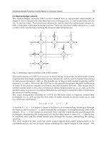
4. TRMS Objects
The proposed multistep Newton-type MPC based on
the state - dependent is implemented on the TRMS, Figure
1. The control objective is to control the yaw and the pitch
angles (h, v) as accurate as possible.
The state variables, the input and output vectors of
TRMS are as follows:
x ( k ) = iah ( k ) h ( k ) S h ( k ) h ( k )
(16)
iav (k ) v (k ) Sv (k ) v (k )
T
(17)
u(k ) = U h (k ) U v (k )
T
y(k ) = h (k ) v (k )
T
Where:
iah: Armature current of the tail motor (A);
(18)
ry(R1)
y
λ: The weight matrix of control efforts with dimension (nu x nu).
The objective function can be written as:
J (k ) = M r (k ) − Y (k ) Q M r (k ) − Y (k )
+U T (k ) RU (k )
Free beam
−h
O1
i =1
ymin yˆ(k + i k ) ymax , i = 1, 2,..., N p
umin uˆ(k + i − 1 k ) umax , i = 1, 2,..., NC
umin uˆ(k + i − 1 k ) umax , i = 1, 2,..., NC
O3
P'1
Figure 1. TRMS Model
The nonlinear continuous state space equations of the
TRMS are expressed in [8]:
Rah
kah h
1
−
iah −
h +
f 6 (U h )
L
L
L
ah
ah
ah
iah
kah h
Btr
f1 (h )
i
ah −
h −
h
J tr
J tr
J tr
lt f 2 (h ) cos v − f 7 ( h ) − f3 ( h )
2
2
S
h
D cos v + E sin v + F
k mv cos v
Sh +
h
2
2
D
cos
+
E
sin
+
F
v
v
R
k
1
d
av
av v
(19)
iav =
−
iav −
v +
f8 (U v )
Lav
Lav
Lav
dt
k
B
f
av v
mr
4 (v )
v
iav −
v −
J mr
J mr
J mr
Sv f5 (v )(lm + k g h cos v ) − f9 ( v )
J
v
2
+
g
(
A
−
B
)
cos
−
C
sin
−
0.5
H
sin
2
v
v
h
v
v
Jv
kt
S v + h
Jv
where
Rah , Lah , kahh , J tr , Btr , lt , D, E , F , km , Rav , Lav ,
kavv , J mr , Bmr , lm , k g , g , A, B, C , H , J v , kt
is the positive constant, h and v is defined as
ISSN 1859-1531 - THE UNIVERSITY OF DANANG, JOURNAL OF SCIENCE AND TECHNOLOGY, NO. 12(85).2014, VOL. 1
−
−
−
+
f (U )
J R
J
J
J R
l f ( ) cos − f ( ) − f ( )
S
D cos + E sin + F
k cos
S +
D cos + E sin + F
d
(
k
)
B
f
(
)
k
(22)
= −
−
−
+
f (U )
dt J R
J
J
J R
S f ( )(l + k cos ) − f ( )
+
J
g
(
A
−
B
)
cos
−
C
sin
−
0.5
H
sin
2
J
k
S +
J
Although this reduced-order model 6 does not affect the
accuracy of the model, it can significantly affect the boot
capacity calculations that reduce processor load and the
speed of the optimization problem. The nonlinear statespace equation above can be approximated and represented
as a state space equation follows: x = A( x) x + Bu
( k ah h )
2
f1 (h )
Btr
h
h
tr
h
ah
6
tr
t
2
tr
h
v
7
tr
h
2
h
h
ah
3
0.5
Alphav
Reference
0.4
0.3
0.2
h
v
0
-0.1
-0.2
v
m
0.1
h
2
v
h
k ah h
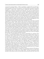
responses of Yaw angle and pitch angle track the reference
in predictive window. Especially, the cross-coupling
channels between Yaw angle and pitch angle is best
known. As soon as h varies, v changes and vice versa.
Then the outputs track the inputs.
Pitch angle - alphav(rad)
kmv cos v
(20)
D cos2 v + E sin 2 v + F
kt h
v = Sv +
(21)
Jv
f1 to f9 is the nonlinear functions.
When Lah<
T
of 6x(k ) = h (k ) Sh (k ) h (k ) v (k ) Sv (k ) v (k ) as follows:
h = Sh +
-0.3
v
2
-0.4
2
v
v
-0.5
0
20
40
60
80
2
av
v
mr
v
mr
v
4
v
5
v
g
mr
h
v
9
mr
v
2
h
v
v
120
140
160
180
200
Figure 3. The response of the pitch angle control loop with
respect to a square - ware
av
v
0.8
v
v
100
Time(s)
v
8
mr
m
av
v
mr
v
41
Alphah
Reference
0.6
v
0.4
v
0.2
h
v
Yaw angle - alphah(rad)
t
v
0
-0.2
-0.4
-0.6
-0.8
-1
-1.2
0
20
40
60
80
100
Time(s)
120
140
160
180
200
Figure 4. The response of the Yaw angle control loop with
respect to a square - ware
5. Simulation results
Figure 2 shows the block diagram of the MPC approach
for TRMS
0.5
Alphav
Reference
0.4
0.3
Pitch angle - alphalv (rad)
0.2
0.1
0
-0.1
-0.2
-0.3
-0.4
-0.5
0
20
40
60
80
100
Time(s)
120
140
160
180
200
Figure 5. The response of the pitch angle control loop with
respect to a substep
0.8
Alphalh
Reference
0.6
Figure 2. Block diagram of the MPC approach
0.4
0.2
Yaw angle - alphalh (rad)
The simulation results with square and substep wares
are represented in the following figures. Figure 3 is the
response of the pitch angle in which the reference is a
square ware. Figure 4 is the response of the Yaw angle in
which the reference is a square ware. Figure 5 is the
response of the pitch angle in which the reference is a
substep. Figure 6 is the response of the Yaw angle in which
the reference is a substep.
Based on the simulation results in 200 seconds when
applying Model Predictive Control for TRMS, the output
0
-0.2
-0.4
-0.6
-0.8
-1
0
20
40
60
80
100
Time(s)
120
140
160
180
Figure 6. The response of the Yaw angle control loop with
respect to a substep
200
42
Nguyen Thi Mai Huong, Mai Trung Thai, Nguyen Huu Chinh, Tran Thien Dung, Lai Khac Lai
6. Conclusion
In this paper, the TRMS system is modelized following
the Np linear models during the predicting horizon at each
sample time k. Then the author applies the MPC for TRMS
and sees that output responses of the yaw and pitch angle
track the followed trajectory, especially cross-coupling
channels in vertical and horizontal directions. However, in
this paper the author has not conducted a test to know
when the disturbances take place, hence this is for further
research in the next study.
REFERENCES
[1] Twin Rotor MIMO System 33-220 User Manual, 1998 (Feedback
Instruments Limited, Crowborough, UK).
[2] A. Rahideh, M.H. Shaheed, Mathematical dynamic modelling of a
twin rotor multiple input–multiple output system, Proceedings of the
IMechE, Part I. Journal of Systems and Control Engineering 221
(2007) 89–101.
[3] Ahmad, S. M., Shaheed, M. H., Chipperfield, A. J., and Tokhi, M.
O, Nonlinear modelling of a twin rotor MIMO system using radial
basis function networks. IEEE National Aerospace and Electronics
Conference, 2000, pp. 313–320.
[4] Ahmad, S. M., Chipperfield, A. J., and Tokhi, M. O. Dynamic
modelling and optimal control of a twin rotor MIMO system. IEEE
National Aerospace and Electronics Conference, 2000, pp. 391–398.
[5] J. M. Maciejowski, Pridictive Control with constraints, Trentice
Hall, 2002.
[6] Shaheed, M. H, Performance analysis of 4 types of conjugate
gradient algorithm in the nonlinear dynamic modelling of a TRMS
using feedforward neural networks, IEEE International Conference
on Systems, man and cybernetics, 2004, pp. 5985–5990.
[7] Islam, B. U., Ahmed, N., Bhatti, D. L., and Khan, S, Controller
design using fuzzy logic for a twin rotor MIMO system, IEEE
International Multi Topic on Conference, 2003, pp. 264–268.
[8] A. Rahideh, M.H. Shaheed, state model pridictive control for a nonlinear
system, Journal of the Franklin Institute 348 (2011) 1983-2004.
[9] A. Rahideh, M.H. Shaheed, constrained output feedback model
predictive control for nonlinear systems, Control Engineering
Practive 20 (2012) 431-443.
[10] Eduardo F. Camacho and Carlos Bordons, Model Predictive
Control, Springer 2007.
[11] Liuping Wang (2008), Model predictive control system design and
implemetation, Springer Verlag.
[12] Nguyen Thi Mai Huong, Mai Trung Thai, Nguyen Huu Chinh, Lai Khac
Lai, Nghien cuu anh huong cua cac tham so trang thai trong he thong hai
canh quat nhieu dau vao nhieu dau ra, Tap chi Khoa hoc Cong nghe –
Dai hoc Thai Nguyen, 2014, so 06, tap 120, trang 87 – 92.
(The Board of Editors received the paper on 09/08/2014, its review was completed on 14/09/2014)