Advanced Model Predictive Control Part 2 pptx
Bạn đang xem bản rút gọn của tài liệu. Xem và tải ngay bản đầy đủ của tài liệu tại đây (790.92 KB, 30 trang )
Fast Model Predictive Control and its Application to Energy Management of Hybrid Electric Vehicles 17
ω T
B
t
d
τ
1200 50 100 144
1200 100 140 142
1600 50 84 140
1600 100 96 137
2000 50 80 140
2000 100 72 134
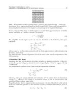
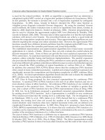
Table 1. Experimental results of fueling delay, t
d
[msecs], and combustion lag, τ [msecs], as
functions of diesel engine speed [rpm] and brake torque [NM]. These results are captured by
measuring the step response of the engine to a step change in the engine brake torque.
For the purpose of this study, we shall employ a 1-st order Pade approximation to model the
fueling time-delay by a rational 1st-order LTI model of
e
−t
d
s
∼
=
−
s + 2/t
d
s + 2/t
d
(18)
The simplified diesel engine model can now be described as the following state-space
equations:
˙
x
1
= −
2
t
d
x
1
+ T
dem
B
˙
x
2
=
4
t
d
x
1
−
1
τ
x
2
− T
dem
B
T
Los s
= mω
T
B
=
1
τ
x
2
− T
Los s
(19)
where x
1
and x
2
are the states associated with the Pade approximation, and combustion lag
dynamics, respectively.
The diesel dynamic shown in Equation (19) will be used in the overall configuration of the
HEV dynamics.
3.2 Simplified CIMG Model
Assuming that the hybrid electric drivetrain includes an armature-controlled CIMG (DC
motor), the applied voltage v
a
controls the motor torque (T
M
)aswellastheangularvelocity
ω of the shaft.
The mathematical dynamics of the CIMG could be represented as follows.
I
a
=
1
L
a
s + R
a
(v
dem
a
− v
em f
) (20)
v
em f
= k
b
ω
T
M
= k
m
I
a
where k
m
and k
b
are torque and back emf constants, v
dem
a
is control effort as of armature
voltage, v
em f
is the back emf voltage, I
a
is armature current, L
a
and R
a
are inductance and
resistance of the armature, respectively.
Regarding the fact that the engine speed is synchronised with that of the CIMG in full-hybrid
mode, the rotational dynamics of the driveline (of joint crankshaft and motor) is given as
follows:
J
˙
ω
+ bω = T
B
+ T
M
− T
L
(21)
19
Fast Model Predictive Control and its
Application to Energy Management of Hybrid Electric Vehicles
18 Will-be-set-by-IN-TECH
where ω is the driveline speed, J is the effective combined moment of rotational inertia of both
engine crankshaft and motor rotor, b is the effective joint damping coefficient, and T
L
is the
vehicle load torque, which is representing the plant disturbance.
The armature-controlled CIMG model in Equation (20) along with the rotational dynamics of
Equations (20) and (21) could be integrated within the following state-space modelling:
˙
x
3
= v
dem
a
−
R
a
L
a
x
3
−
K
b
J
x
4
˙
x
4
=
1
τ
x
2
+
K
b
L
a
x
3
−
b
J
x
4
− T
Los s
− T
L
ω =
1
J
x
4
T
M
=
K
b
L
a
x
3
(22)
where x
3
and x
4
are the states associated with the armature circuit, and driveline rotational
dynamics, respectively.
A simplified but realistic simulation model with detailed component representations of diesel
engine and DC electric motor (CIMG) will be used as a basis for deriving the hybrid model as
discussed in the subsequent section.
3.3 Simplified hybrid diesel electric vehicle model
Based on the state-space representation of both the diesel ICE and electric CIMG, given in
Equation (19) and Equation (22), respectively, we can now build our simplified 4-state HEV
model to demonstrate our proposed approach.
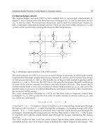
A schematic representation of the simplified parallel hybrid diesel electric vehicle model is
shown in Figure 3.
st
d
e
−
1
1
+s
τ
aa
b
RsL
k
+
b
k
emf
v
dem
a
v
bJs +
1
ω
L
T
ind
T
Loss
T
M
T
dem
B
T
B
T
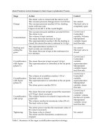
Fig. 3. Simplified model of the parallel Hybrid Diesel Electric Vehicle.
Recall that, as illustrated in Figure 2, the setpoint torque commands (indicated by T
req
B
and
T
req
M
) are provided to the controller by a high-level static optimisation algorithm, not discussed
in this study – see (Dextreit et al., 2008) for more details. Also, in this figure the engine
20
Advanced Model Predictive Control
Fast Model Predictive Control and its Application to Energy Management of Hybrid Electric Vehicles 19
brake torque and the CIMG torque are estimated feedback signals. However, the details of
the estimation approach are not included here. For the sake of simplicity, in this work we
shall assume that both engine and CIMG output torques are available to measure.
In addition, due to there being in "full hybrid" mode, it is assumed that the ICE-CIMG clutch
is fully engaged and hence the clutch model is excluded from the main HEV dynamics - it
was previously shown in Figure 2. Also, the gear setting is disregarded at this simplified
model, as discussed earlier. Furthermore, the look-up mapping table of CIMG torque request
vs armature voltage request (v
dem
a
) is not shown in this model for the sake of simplicity.
The overall state-space equations of the simplified HEV model is represented by
˙
x
=
⎡
⎢
⎢
⎢
⎣
−
2
t
d
00 0
4
t
d
−
1
τ
00
00
−
R
a
L
a
−
K
b
J
0
1
τ
K
b
L
a
−
m+b
J
⎤
⎥
⎥
⎥
⎦
x
+
⎡
⎢
⎢
⎣
10
−10
01
00
⎤
⎥
⎥
⎦
u
+
⎡
⎢
⎢
⎣
0
0
0
−1
⎤
⎥
⎥
⎦
T
L
y =
0
1
τ
0 −
m
J
00
K
b
L
a
0
x
(23)
where x
∈ R
4
is the state of the system obtained from Equations (19) and (22), u =
[
T
dem
B
v
dem
a
]
T
and y =[T
B
T
M
]
T
are control signals and HEV torque outputs, respectively.
The state-space equations of Equation (23) will be used in designing the proposed fast model
predictive control described in Section 2. Some representative simulation results of HEV
energy management case study will be shown in the next section to highlight some advances
of our proposed embedded predictive control system.
4. Simulation results
In this section, we shall present our proposed Fast MPC algorithm described in Section 2
for the application of the simplified HEV energy management system discussed in Section 3.
The problem addressed in the next subsection is to discuss required setpoint torque tracking
problem with appropriate optimisation objective leading towards applying our fast MPC
design to the HEV energy management problem as illustrated by some of our simulation
results.
4.1 HEV energy management optimisation objective and control strategy
For the HEV energy management application subject to the objective function and constraints,
HEV demanded torques are found at each time step by solving the optimisation problem of
Equation (16) with the following data:
x
min
=
[
0, −56, −300, 0
]
T
x
max
=
[
18, 56, 300, 360
]
T
u
min
=
[
0, −380
]
T
(24)
u
max
=
[
400, 380
]
T
˙
u
max
= −
˙
u
min
=
[
0.5, 4
]
T
21
Fast Model Predictive Control and its
Application to Energy Management of Hybrid Electric Vehicles
20 Will-be-set-by-IN-TECH
For our HEV setpoint tracking problem, based on Equation (16), y
k
=[T
B
T
M
]
T
is the HEV
torque outputs (ICE torque and CIMG torque, respectively), y
req
k
=[T
req
B
T
req
M
]
T
is the tracking
setpoint torques commands , w
k
∈ R
4
is the discretised vehicle load torque, u
k
=[T
dem
B
v
dem
a
]
T
is the demanded HEV torques (control efforts) generated in real-time by the controller.
An equated LTI discrete-time system of the continuous-time state-space dynamics described
in Equation (23) is obtained using a sampling interval t
s
(see Table 2). The plant initial
condition x
0
∈ R
4
is assumed zero in our simulations.
The parameters used in the proposed Fast MPC design together with other physical constants
of the simplified HEV model are provided in Table 2.
Parameter Value Unit
Sampling time (t
s
) 8 msecs
ICE fueling delay (t
d
) 90 msecs
ICE combustion lag (τ) 140 msecs
Motor armature resistance (R
a
) 1 Ohms
Motor armature inductance (L
a
) 0.3 Henrys
Motor torque constant (k
m
) 0.25 NM.Amp
−1
Motor back emf constant (k
b
) 0.25 Volts.secs.rad
−1
Effective hybrid rotational inertia (J) 0.6 kg.m
2
/s
2
Effective hybrid rotational damping (b) 0.125 Nms
FMPC horizon (N) 20 -
Output penalising matrix (Q
y
) diag(400,200) -
Control penalising matrix (Q
u
) diag(0.01,0.01) -
Table 2. Physical constants and FMPC design parameters in regard to the HEV model case
study.
In the next subsection, the closed-loopbehavior of the HEV energy management problem with
our FMPC controller placed in the feedback loop has been evaluated based on the high-fidelity
simplified model of the HEV described in Section 3.
4.2 Simulation results
Our simulations have been carried out in Simulink and implemented in discrete-time using a
zero-order hold with a sampling time of t
s
= 8msecs–seeTable2.
We shall emphasis that optimization based model predictive control (MPC) techniques,
including the proposed fast MPC design methodology, require knowledge about future
horizon (driving conditions in this case study). These future driving conditions in our case
study include setpoint torque commands (requested by driver) and vehicle load torque. This
fact will make implementation of all sort of optimisation based predictive control algorithms
even more arduous to be applied in real time.
For the purpose of simulations, assuming that the future driving cycle (i.e. torque references
and vehicle load) are entirely known could be perhaps an acceptable assumption. In our
simulations, the future driving cycle is unknown whilst retaining constant for the whole
horizon of N samples. However, if the future driving cycle could be entirely known, the
performance of the proposed FMPC would be superior than those shown here.
22
Advanced Model Predictive Control
Fast Model Predictive Control and its Application to Energy Management of Hybrid Electric Vehicles 21
Figure 4 shows a typical simulation results for the period of 20 secs in tracking requested
setpoint HEV torques. During this simulation period, the system is in hybrid mode as both
ICE torque and CIMG torque are requested.
0 5 10 15 20
−20
0
20
40
60
Time (Secs)
T
B
[NM]
T
B
req
T
B
(a) Engine Brake Torque.
0 5 10 15 20
15
20
25
30
35
40
45
Time (Secs)
T
CIMG
[NM]
T
CIMG
req
T
CIMG
(b) CIMG Torque.
Fig. 4. Simulation results of the HEV torque setpoints and outputs using the proposed FMPC
algorithm.
As shown in Figure 4, despite the fact that the HEV energy management is a coupled
Two-Input Two-Output (TITO) dynamical system, both the diesel ICE and the DC electric
motor have successfully tracked the requested torque setpoints. At times t
= 5secsand
t
= 15 secs , the TITO controller is requested for an increased and decreased ICE torques,
respectively to which the fast MPC algorithm could precisely follow those commands, as
illustrated in Figure 4(a). Similarly, there was an increased request for the CIMG torque (from
20 NM to 40 NM) at time t
= 10 secs, and the controller has successfully delivered this torque
request, as depicted in Figure 4(b).
This is noted that our torque manager structure, as stated earlier, assumes that setpoint torque
commands are provided by some sort of static optimisation algorithms. The designed FMPC
is then enquired to optimise control efforts so as to track the requested torque references.
Figure 5 shows the load torque transient used in our simulations (being modeled as a plant
disturbance), ICE torque loss and control efforts generated by the FMPC. We have assumed
that plant disturbance (vehicle load) is known and available to controller. In reality, this might
be an infeasible assumption where an estimation algorithm is required to estimate the vehicle
load torque w
k
over the prediction horizon. Also, as mentioned earlier, the estimation of future
driving conditions must be made online. Due to lack of space, however, we shall preclude
addressing a detailed discussion in this course.
Figure 5(c) shows that the FMPC fully satisfies the required optimisation constraints as of
Equation (24).
Figure 6 shows simulation results in regard to driveline speed and vehicle speed. It
is worthwhile to point out that as illustrated in Figure 6(a), by requesting large torque
commands, we have in fact violated our empirical HEV modeling assumption in that driveline
speed must be limited to ω
=[1200, 2000]rpm. However, it can be seen that the FMPC can still
successfully control the HEV energy endamagement dynamics in real-time. The vehicle speed
shown in Figure 6(b) has been calculated using a dynamic model of the vehicle as a function
of the driveline speed which is not discussed here.
It is also important to mention that fueling delay and combustion lag are functions of engine
speed and brake torque – see Table 1. However, in designing our fast MPC algorithm we
23
Fast Model Predictive Control and its
Application to Energy Management of Hybrid Electric Vehicles
22 Will-be-set-by-IN-TECH
0 5 10 15 20
0
10
20
30
40
50
Time (Secs)
T
Load
[NM]
(a) Vehicle (load) Torque.
0 5 10 15 20
0
10
20
30
40
Time (Secs)
T
Loss
[NM]
Ancilary Torque
Friction
Pumping loss
Total losses
(b) Torque Loss.
0 5 10 15 20
0
100
200
300
400
Time (Secs)
u(t)
ICE [NM]
CIMG [Volt]
(c) Control signals.
Fig. 5. Simulation results of vehicle load, Torque loss, and Control efforts.
0 5 10 15 20
500
1000
1500
2000
2500
3000
Time (Secs)
w (rpm)
(a) Driveline Speed.
0 5 10 15 20
0
5
10
15
20
25
Time (Secs)
v (mph)
(b) Vehicle Speed.
Fig. 6. Simulation results of parallel diesel HEV driveline speed and vehicle speed.
require to utilise an LTI model of the HEV energy management plant. Towards this end, we
use the numerical values of τ
= 140 msecs and t
d
= 90 msecs, in our design to capture worst
case of the ICE speed-dependant parameters. However, the simulation results are based on
the actual time-varying speed-dependant parameters of the ICE, namely τ and t
d
.
Regarding the real-time simulations in Simulink (fixed-step) using our Matlab custom
S-function codes with a sampling time of t
s
, the simulation time required for a single run
of 20 secs was approximately 500 times faster than real-time running a Toshiba Portege
laptop with an Intel(R) Core(TM) i5 processor, at 2.4GHz under Windows 7 Pro platform.
24
Advanced Model Predictive Control
Fast Model Predictive Control and its Application to Energy Management of Hybrid Electric Vehicles 23
Without doubt, this shows a significant improvement on the computational capability of the
control action that could potentially permit any sort of fast MPC algorithms to be run using
inexpensive low-speed CPUs under possibly kilo Hertz control rates.
5. Conclusions
The aim of this chapter was to present a new Fast Model Predictive Control (FMPC) algorithm
with an application for the energy management of hybrid electric vehicles (HEVs). The
main goal of energy management in hybrid electric vehicles is to reduce the CO
2
emissions
with enhanced fuel consumption for a hybrid powertrain control system. The applicability
of conventional MPC in the energy management setting, however, has shown a main
drawback of these algorithms where they currently cannot be implemented on-line due to
the burdensome real-time numerical optimisation, arising due to e.g. hardware constraints
and limitation of online calculations. The proposed FMPC design architecture could resolve
such shortcomings of the standard MPC algorithms. In fact, such a custom method, is able
to speed up the control action, by exploiting particular structure of the MPC problem, much
faster than that of the conventional MPC methods. Moreover, our proposed FMPC design
methodology does not explicitly utilise any knowledge in regard to the future driving cycle.
Simulation results illustrated that FMPC could be a very promising on-line control design
algorithm and could play a key role in a wide variety of challenging complex automotive
applications in the future.
6. Acknowledgment
This work was supported by EPSRC, UK, under framework "Low Carbon Vehicles Integrated
Delivery Programme", Ref. EP/H050337/1.
We would like to thank Dr. Jacob Mattingley and Yang Wang, from Stanford University, for
their valuable comments and discussions which helped us in preparation of an earlier version
of our simulation results.
7. References
Anderson, C.D. & Anderson, J. (2010). Electric and Hybrid Cars: A History, 2nd Edition,
McFarland & Co Inc.
Bartlett, R.A.; Wachter, A. & Biegler, L.T. (2000). Active set vs. interior point strategies for
model predictive control, Proc. of the American Control Conf., Vol. 6, pp. 4229-4233.
Baumann, B.M.; Washington, G.; Glenn, B.C. & Rizzoni, G. (2000). Mechatronic design and
control of hybrid electric vehicles, IEEE/ASME Trans. On Mechatronics, 5(1): 58-72.
Beccuti, A.G.; Papafotiou, G.; Frasca, R. & Morari, M.; . (2007). Explicit Hybrid Model
Predictive Control of the dc-dc Boost Converter, IEEE Power Electronics Specialists
Conference, PESC 2007, Orlando, Florida, USA, pp. 2503-2509
Bemporad, A. (2004). Hybrid Toolbox - User’s Guide.
URL: bemporad/hybrid/toolbox
Bemporad, A.; Morari, M; Dua, V. & Pistikopoulos, E.N. (2002). The explicit linear quadratic
regulator for constrained systems, Automatica 38: 3-20.
Bemporad, A. & Morary, M. (1999). Control of systems integrating logic, dynamics, and
constraints, Automatica 35: 407-427.
25
Fast Model Predictive Control and its
Application to Energy Management of Hybrid Electric Vehicles
24 Will-be-set-by-IN-TECH
Cacciatori, E.; Vaughan, N.D. & Marco, J. (2006 ). Evaluating the Impact of Driveability
Requirements on the Performance of an Energy Management Control Architecture
for a Hybrid Electric Vehicle, The 2nd International IEE Conference on Automotive
Electronics,IEESavoyPlace,UK.
Camacho, E.F. & Bordons C. (2004). Model Predictive Control,Springer-Verlag.
Cikanek, S.R. & Bailey, K.E. (2002). Regenerative braking system for a hybrid electric vehicle,
In Proc. of the American Control Conf., Anchorage, AK, Vol. 4, pp. 3129-3134.
Cundev, D. (2010). Hybrid-electric Cars and Control Systems: Control strategy of car hybrid system
and its experimental confirmation, LAP LAMBERT Academic Publishing.
De la Pena, D.M.; Bemporad, A. & Filippi, C. (2006). Robust explicit MPC based on
approximate multiparametric convex programming, IEEE Transactions on Automatic
Control 51: 1399-1403.
Del Re, L.; Glielmo, L.; Guardiola, C. & Kolmanovsky, I. (Eds.) (2010). Automotive Model
Predictive Control: Models, Methods and Applications, 1st edn, Springer.
Dextreit, C.; Assadian, F.; Kolmanovsky, I.; Mahtani, J. & Burnham, K. (2008). Hybrid electric
vehicle energy management using game theory, SAE World Congress & Exhibition,
SAE Paper No. 2008-01-1317.
Fekri, S. & Assadian, F. (2011). Application of Robust Multivariable Control on Energy
Management of Hybrid Electric Vehicles, International Journal of Vehicle Design
(IJVD), Special Issue on "Automotive Mechatronics: Innovations in Design, Analysis and
Implementation", March 2011, under review.
Fuhs, A. (2008). Hybrid Vehicles, 1st edn, CRC Press.
Gelb, A. (1974). Applied Optimal Estimation,MITPress,MA,USA.
Grewal, M.S. & Andrews, A.P. (1993). Kalman Filtering: Theory and Practice, Prentice-Hall.
Hofman, T. & Druten, R.V. (2004). Energy analysis of hybrid vehicle powertrains, In Proc. Of
the IEEE Int. Symp. On Vehicular Power and Propulsion,Paris,France.
Husain, I. (2003). Electric and Hybrid Vehicles: Design Fundamentals, 1st edn, CRC Press.
Johnson, V.H; Wipke, K.B. & Rausen, D.J. (2000). HEV control strategy for real-time
optimization of fuel economy and emissions, In Proc. of the Future Car Congress,
Washington DC, USA.
Kaszynski, M. & Sawodny, O. (2008). Modeling and identification of a built-in turbocharged
diesel engine using standardized on-board measurement signals, Proc. of IEEE
International Conference on Control Applications (CCA 2008), pp. 7-12.
Kessels, J. (2007). Energy Management for Automotive Power Nets, PhD thesis, Faculteit Electrical
Engineering, Technische Universiteit Eindhoven, The Netherlands.
Khayyam, H.; Kouzani, A.; Nahavandi, S.; Marano, V. & Rizzoni, G. (2010). Energy
Management, InTech, chapter Intelligent Energy Management in Hybrid Electric
Vehicles, pp. 147-175.
Kolmanovsky, I.; Siverguina, I. & Lygoe, B. (2002b). Optimization of powertrain operating
policy for feasibility assessment and calibration: Stochastic dynamic programming
approach, In Proc. of the American Control Conf., Anchorage, AK, pp. 1425-1430.
Kwon, W.H. & Han, S. (2005). Receding Horizon Control,Springer-Verlag.
Lewis, J.B. (1980). Automotive engine control: A linear quadratic approach, PhD thesis, Dept. of
Electrical Engineering and Computer Science, Massachusetts Institute of Technology,
MA, USA.
26
Advanced Model Predictive Control
Fast Model Predictive Control and its Application to Energy Management of Hybrid Electric Vehicles 25
Ling, K.V.; Wu, B.F. & Maciejowski, J.M. (2008). Embedded model predictive control (MPC)
using a FPGA, Proc. 17th IFAC World Congress, pp. 15250-15255.
Maciejowski, J.M. (2002). Predictive Control with Constraints, Prentice-Hal.
Mattingley, J. & Boyd, S. (2010). Real-time convex optimization in signal processing, IEEE
Signal Processing Magazine 27: 50-61.
Mattingley, J. & Boyd, S. (2010). CVXGEN: A code generator for embedded convex
optimization, working manuscript.
Mattingley & Boyd (2009). Automatic Code Generation for Real-Time Convex Optimization,
Cambridge University, chapter Convex Optimization in Signal Processing and
Communications.
Mehrotra, S. (1992). On the implementation of a primal-dual interior point method, SIAM
Journal on Optimization 2: 575-601.
Milman, R. & Davidson, E.J. (2008). A fast MPC algorithm using nonfeasible active set
methods, Journal of Optimization Theory and Applications 139: 591-616.
Milman, R. & Davidson, E.J. (2003). Fast computation of the quadratic programming
subproblem in MPC, Proc. of the American Control Conf., pp. 4723-4729.
Narciso, D.A.C.; Faisca, N.P. & Pistikopoulos, E.N. (2008). A framework for multi-parametric
programming and control
˚
Uanoverview,Proc. of IEEE International Engineering
Management Conference, IEMC Europe 2008, pp. 1-5.
Peng, J.; Roos, C. & Terlaky, T. (2002). Self-Regularity: A New Paradigm for Primal-Dual
Interior-Point Algorithms, Princeton University Press.
Potra P.A. & Wright S.J. (2000). Interior-point methods, Journal of Computational and Applied
Mathematics 124: 281-302.
Ramsbottom, M. & Assadian, F. (2006). Use of Approximate Dynamic Programming for
the Control of a Mild Hybrid , Proceedings of WMG Hybrid Conference,Universityof
Warwick, Warwick, United Kingdom, December 12-13.
Rao, C.V.; Wright, S.J. & Rawlings, J.B. (1998). Applications of interior-point methods to model
predictive control, Journal of Optimization, Theory and Applications 99: 723-757.
Renegar, J. & Overton, M. (2001). A Mathematical View of Interior-point Methods in Convex
Optimization, Society for Industrial & Applied Mathematics, USA.
Ripaccioli, G.; Bemporad, A.; Assadian, F.; Dextreit, C.; Di Cairano, S. & Kolmanovsky
I.V. (2009). chapter Hybrid Modeling, Identification, and Predictive Control: An
Application to Hybrid Electric Vehicle Energy Management, R. Majumdar and P.
Tabuada (Eds.), Proc. of the 12th International Conference on Hybrid Systems Computation
and Control (HSCC 2009), Springer-Verlag Berlin Heidelberg, pp. 321
˝
U335.
Rousseau, G.; Sinoquet, D.; Sciarretta, A & Yohan Milhau. (2008). Design Optimisation
and Optimal Control for Hybrid Vehicles, In Proc. of the International Conference on
Engineering Optimization, EngOpt 2008, Rio de Janeiro, Brazil, June 2008.
Schouten, N.J.; Salman, M.A. & Kheir, N.A. (2002). Fuzzy logic control for parallel hybrid
vehicles, IEEE Trans. on Control Systems Technology 10(3): 460-468.
Sciarretta, A. & Guzzella, L. (2007). Control of hybrid electric vehicles, IEEE Control Systems
Magazine pp. 60-70.
Sontag, E. (1981). Nonlinear regulation: The piecewise linear approach, IEEE Trans. on
Automatic Control 26(2): 346-358.
27
Fast Model Predictive Control and its
Application to Energy Management of Hybrid Electric Vehicles
26 Will-be-set-by-IN-TECH
Steinmaurer, G. & Del Re, L. (2005). Optimal energy management for mild hybrid operation
of vehicles with an integrated starter generator, In Proc. of the SAE World Congress,
Detroit, Michigan.
Tate, E. & Boyd, S. (2001). Towards finding the ultimate limits of performance for hybrid
electric vehicles, In Proc. of the SAE Future Transportation Technology Conf.,CostaMesa,
CA.
Tondel, P.; Johansen, T.A. & Bemporad, A. (2003). An algorithm for multi-parametric
quadratic programming and explicit MPC solutions, Automatica, 39(3): 489-497.
Torrisi, F.D. & Bemporad, A. (2004). Hysdel - a tool for generating computational hybrid
models, IEEE Trans. on Control Systems Technology 12(2): 235-249.
Vandenberghe, L. (2010). The CVXOPT linear and quadratic cone program solvers. working
manuscript.
Vandenberghe, L. & Boyd S. (2004). Convex Optimization, Cambridge University Press.
Wang, Y. & Boyd, S. (2010). Fast model predictive control using online optimization, J. Optim.
Theory Appl 18: 267-278.
Wang, Y. & Boyd, S. (2008). Fast model predictive control using online optimization,
Proceedings of the 17th IFAC World Congress, Seoul, Korea, pp. 6974-6979.
Wright, S.J. (1997). Primal-dual interior-point methods,SIAM.
28
Advanced Model Predictive Control
2
Fast Nonlinear Model Predictive Control using
Second Order Volterra Models Based
Multi-agent Approach
Bennasr Hichem and M’Sahli Faouzi
Institut Supérieur Des Etudes Technologiques de SFAX
Ecole Nationale d’ingénieur de Monastir
Tunisia
1. Introduction
Model predictive control (MPC) refers to a class of computer control algorithms that utilize
a process model to predict the future response of a plant. During the past twenty years, a
great progress has been made in the industrial MPC field. Today, MPC has become the most
widely implemented process control technology. One of the main reasons for its application
in the industry is that it can take account of physical and operational constraints. In classical
model predictive control (MPC), the control action at each time step is obtained by solving
an online optimization problem. If it is possible, MPC algorithms based on linear models
should be used because of low computational complexity [Maciejowski J,2002]. Since
properties of many technological processes are nonlinear, different nonlinear MPC
techniques have been developed [Qin, S. J et al, 2003]. The structure of the nonlinear model
and the way it is used on-line affect the accuracy, the computational burden and the
reliability of nonlinear MPC. Several different attempts to reduce computational complexity
have been released during the last thirty years. The simplest way to reduce on-line
computation is to transform the NMPC problem into LMPC. The nonlinear system is
transformed into a linear system using a feedback-linearizing law, the input constraints are
mapped into constraints on the manipulated input of the transformed system and the
obtained constrained linear system is controlled using LMPC [Kurtz M.J et al,1997]. An
interesting strategy is presented in [Arahal M.R et al.,1998], when the linear model is used to
predict future process behavior and the nonlinear model is used to compute the effect of the
past input moves. The most straightforward technique used to implement fuzzy models
[Fischer M et al.,1998] is based on a linearization method. The accuracy of the linear model
can be improved by relinearizing the model equations several times over a sampling period
or by linearizing the model along the computed trajectory [Mollov S.,et al.,2004].Another
approach has been used by a number of researchers such as in [Brooms A et al., 2000], where
the NMPC problem is reduced to an LMPC problem at each time step using a successive
linearization. The structure of certain nonlinear empirical models allows the NMPC
optimization problem to be solved more efficiently than is possible with other forms. Such
an approach will be followed in [Abonyi, J et al,2000]. An algorithm for controller
reconfiguration for non-linear systems based on a combination of a multiple model
Advanced Model Predictive Control
30
estimator and a generalized predictive controller is presented in [Kanev, S et al., 2000], in
which a set of models are constructed. Each corresponding to a different operating condition
of the system and an interacting multiple model estimators is utilized to yield a
reconstruction of the state of the non-linear system. For unconstrained control based on
linear process models and a quadratic cost function, the control sequence can be analytically
calculated. When linear constraints are taken into account, the solution can be found using
quadratic programming techniques. With the introduction of a nonlinear model into MPC
scheme, a nonlinear programming technique (NLP) has to be solved at each sampling time
to compute the future manipulated variables in on-line optimization that is generally non-
convex which make their implementation difficult for real time control. During the past
decade significant theoretical results as well as advances in the implementation strategies of
NMPC have been obtained and NMPC has been successfully applied in practice to relatively
slow plants, mainly in the process industry. However, the application of such techniques for
fast nonlinear systems remains a widely opened problem due to the computation burden
associated with solving an open loop optimal control problem. Most of the research has
focused on computations carried out by one agent. In [Negenborn R et al., 2004], a survey
how a distributed multi-agent MPC setting can reduce the computations of a single MPC
agent. Moreover, researchers have investigated feedback linearization model predictive
control (FLC-MPC) schemes for their ability to handle constraints on input and output
[Soest Van W.R et al., 2005]. These approaches reduce the on-line computation by
transforming the NLMPC problem into a LMPC and quadratic programming can be used to
handle constraints. When sampling times become so short, the computation times for QP
solution can no longer be neglected [Jaochim H et al., 2006]. In [Didier G ,2006], a distributed
model predictive control is considered and the proposed strategy allows dramatic reduction
of the computational requirement for solving large-scale nonlinear MPC problem due to
computation parallelism. However, recent advancements in MPC allow for a faster online
solution by shifting some of the computational burden off-line. We can notice that many
optimization algorithm solutions for NMPC have been investigated lately; however, an
analytical solution in NMPC approach is usually impossible to find. One possible way to
address computational complexity is to decentralize the optimization tasks. Attention has
been focused on multi-agent model predictive control approach [H.Ben Nasr et
al.,2008a,b,c,d,e]. There are multiple agents in multi-agent model predictive control. Each
uses a model of its sub-system to determine which action to take. Decentralized agent
architecture and decentralized model decomposition are then chosen, in which there are
numerous agents that do not have any interaction among one another. A methodology
based multiagent has been investigated in the implementation of a given predictive control
law for nonlinear systems. Such procedure relies on the decomposition of the overall system
into subsystems and a multiple agents each uses a model of its sub-system to determine
which action to take.
In this chapter book, new NMPC scheme based MAMPC (Multiagent model predictive
control) is implemented to reduce the computational effort. The performance of the proposed
controllers is evaluated by applying to single input-single output (SISO) control of non linear
system. Moreover, in general, the optimization problem is nonconvex and leads to many
difficulties impacting on implementation of MPC. These difficulties are related to feasibility
and optimality, computation and stability aspects. In order to avoid solving nonconvex
optimization problem, MAMPC (Multiagent model predictive control) optimization
procedure, a method for convex NMPC was also developed in this chapter book. Theoretical
Fast Nonlinear Model Predictive Control using
Second Order Volterra Models Based Multi-agent Approach
31
analysis and simulation results demonstrate better performance of the MAMPC over a
conventional NMPC based on sequential quadratic programming (SQP) in tracking the set
point changes as well as stabilizing the operation in the presence of input disturbances. In this
work, our main objective has been to illustrate the potential advantage of nonlinear predictive
control based multiagent when applied to nonlinear systems. The suggested approach was to
identify a new control algorithm that in essence is a bridge between linear and nonlinear
control. This resulted in the development of the MAMPC approach. Through simulation-based
comparisons, it is shown that a MAMPC control algorithm is capable of delivering
significantly improved control performance in comparison to a conventional NMPC, so that
the difficulty of minimizing the performance function for nonlinear predictive control is
avoided, which is usually carried by the use of NLP solved at each sampling time that
generally is non-convex. In this chapter book we describe algorithm that find the solution of a
non-convex programming and also demonstrated that global nonlinear requirements can
effectively be resolved by considering smaller regimes. The simulation example shows that the
multi-agent compares favorably with respect to a numerical optimization routine. Moreover,
the MAMPC reduces the online computational burden and hence has the potential to be
applied to the system with faster time constants.
2. Statement of the problem
2.1 Process model
A broad class of physical systems can be represented using the Volterra model. Particularly,
it was shown that a truncated Volterra model could represent any non-linear system, time-
invariant with fading memory. This model is thus particularly attractive for non-linear
systems modeling and identification purpose. One of the main advantages of the Volterra
model is its linearity-in-parameters, i.e. the kernel coefficients. This property allows the
extension of some results established for linear model identification to this model. In this
work, we consider the control of a class of single-input single output non-linear system
described by the following non-linear discrete-time parametric second-order Volterra model
(Haber et al. 1999a,b):
0
1111
() () () ()()()
y
uu
n
nn
i
ii ij
iiij
yk y ayk i buk i buk iuk j k
ε
====
= + −+ −+ − − +
(1)
Where
0
y is a bias term, ()
y
k is the output, ()uk is the input, ,
ii
aband
i
j
b are the parameters
of the parametric Volterra model,
u
n and
y
n are the number of lags on the input and the
output, respectively.
()k
ε
Contains all terms up to second-order. One advantage of using the
parametric Volterra model is that the one-ahead prediction problem can be formulated as a
linear regression, which simplifies the identification of the parameters from input-output
data. Therefore, the model given by “Equation (1)” can be written as:
() () ().
T
y
kkk
θφ ε
=+
(2)
With:
012 12 1,1 ,
,,,, ,,,, , ,,
yuuu
T
nnnn
yaa a bb b b b
θ
=
(3)
Advanced Model Predictive Control
32
22
( ) 1, ( 1), , ( ), ( 1), , ( 1), , ( ) .
T
yu
k yk ykn uk uk ukn
φ
=−−−−−
(4)
Where
()k
φ
and
θ
are the regressor and the parameter vectors, respectively. The model
“Equation (3)” is linear in parameters, and its regressors and parameters may be identified
from input output information. Moreover, from identification point of view, parametric
Volterra models are superior to Volterra series models in the sense that the number of
parameters needed to approximate a process are generally much less with parametric
Volterra models. This is due to the fact that Volterra models only include previous inputs,
while the model (1) includes previous outputs as well as previous inputs.
2.2 Optimization criteria
The purpose of the control strategy is to compute future control moves which will minimize
some performance function based on the desired output trajectory over a prediction
horizon, subject to constraints on input and output signals [D.W. Clarke et al.,1987]. The
most common objective cost function, also used here, is:
2
1
22
12 ,
1
(,, ) (( )( /)) ( ( 1))
u
N
N
uj
jN j
JN N N wk j yk j k uk j
δλ
∧
==
=+−++Δ+−
(5)
Subject to
(1) 1
()(1)()1
low hi
g
hu
low hi
g
hu
uu
jj
u
f
or
j
N
ukuk
j
uk
f
or
j
N
Δ≤Δ+−≤Δ ≤≤
≤+−≤ ≤≤
(6)
Where
1
N is the minimum prediction horizon,
2
N is the maximum prediction horizon,
(/)
y
k
j
k
∧
+ is an optimum j-step ahead prediction of the system output on data up to time k,
()wk j+ is a sequence of future set points,
2u
NN≤ is the control horizon, and
11
() (,, )
uu
jj N N
λλλ
=
=
are control-weighting factors usually assumed to be equal to each
other used to penalize the control increments.
[
]
(1),1,
u
uk
jj
NΔ+− ∈ , is a sequence of future
control increments computed by the optimization problem at time k;
(1)0uk jΔ+−= for
u
jN> . For the constraints , , ,
low hi
g
hlowhi
g
h
uu u uΔΔ, are respectively the lower limit, upper
limit, lower derivative limit and higher derivative limit of the control input. Using the
quadratic prediction equation of the model, the cost function becomes fourth degree
equation in the control increments. Th objective finction never exeeds fourth order,
regardless of the value of the prediction horizon. (Haber, 1999a, 1999b)
2.3 Nonlinear Predictive Control
Despite of the wide exposure of and the intensive research efforts attracted over the past few
decades on Nonlinear model predictive control (NLMPC), this control strategy is still being
perceived as an academic concept rather than a practicable control technique. However,
nonlinear model predictive control is gaining popularity in the industrial community. The
formulations for these controllers vary widely, and almost the only common principle is to
retain nonlinearities in the process model [Matthew et al.,2002]. In nonlinear control, a
receding horizon approach is typically used, which can be summarized in the following
steps:
Fast Nonlinear Model Predictive Control using
Second Order Volterra Models Based Multi-agent Approach
33
1. At time k, solve, on-line, an open-loop optimal control problem over some future
interval, taking into account the current and future constraints.
2.
Apply the first step in the optimal control sequence.
3.
Receding strategy so that at each instant the horizon is displaced towards the future,
which involves the application of the first control signal of the sequence calculated at
each step.
The process to control is assumed to be represented by a mono-variable second order
parametric Volterra model. The model given by (1) can be expressed as:
11112
01 212
1
()
()() ()() (,)()
()
k
Aq yk y B q uk B q q u k
q
ε
−−−−
−
=+ + +
Δ
(7)
Where are two polynomials of the backward shifting operator
1
q
−
given by :
11
1
11
1111
()1
()1
na
na
nb
nb
Aq aq a q
Bq bq b q
−− −
−− −
=+ + +
=+ + +
(8)
11
21 2
(,)Bq q
−−
represents the quadratic term of the Volterra model, this quantity is defined
by:
112
21 2 2
0
(,)() ( )( )
nb nb
nm
nmn
Bq q uk b uk nuk m
−−
==
=−−
(9)
The incremental predictive form of the parametric Volterra model can be expressed as a
function of the current and future control increments :
1112
12
01 2
() ()()(,)()
jj j
y
kj v vq ukj vq q ukj
∧
−−−
+= + Δ ++ Δ +
(10)
With
11
**
12
0
1
11
*
12
1
1
2
2
() ( ) ( )
() 1,2,,
1,2, , 1,2, ,
nb j nb j
j
oj i im
ij mi
nb j
j
iim
i
mj
j
im
im
vyGyk ukjmukji
vv ukjm i j
vijandmj
δδ
δ
δ
+− +−
=+ =
+−
=+
=+ + + Δ +− Δ +−
=+ Δ +− =
===
(11)
The effect of selecting the parameters and the coefficient of the predictive control are not
investigated here, for more detail see(Haber et al., 1999a) . Replacing the incremental output
by his expression, the cost function (5) can be written as follows:
22
012012
()()
T
T
Jvwvuvu vwvuvu uu
λ
=−+ + −+ + +
(12)
With constraints, the cost function can be minimized numerically by a one-dimensional
search algorithm (dynamic algorithm programming). Without constraints the solution leads
to a third-degree one-dimensional equation [F.J.Doyle et al.,1995].
Advanced Model Predictive Control
34
3. Multi-agent Model Predictive Control
3.1 Control and design
The main idea of the proposed concept model predictive control is to transform the
nonlinear optimization procedure used in a standard way into sub-problems, in which the
global task can be resolved. The objective of this approach is to regulate the nonlinear
system output to the expected values and satisfying the above constraints. This can be done
as follows. The global system can first be decomposed on sub-systems independent of one
another, for each sub-system an MPC unit sub-system is made constituting the agent
controller i. Based on an analytical solution, which corresponds to the solution of the local
receding horizon sub-problems, a logic unit switching tries to find the best sequence of
actions sent to the nonlinear system and gives the desired trajectory. Sequences of actions
that bring the global system in a desired trajectory are made and avoid any violated
constraints on actions. The multi-agent controller consists of synchronizing the output of the
true system at every decision step k with the reference trajectory. In fact, at every decision
step the right action is the one that will cause the agent to be the most successful. The
parallel controller structure is based on the fact that a neural network can be used to learn
from the feedback error controller non linear system. A neural network controller is also
made on, in objective to take handle the results of the actions on the global system and
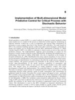
monitor the closed-loop system. Figure 1, shows the architecture of the multi-agent
controller. In the multi-agent context, the agents are the controllers and the non linear
system is the environment.
Fig. 1. Architecture of Multi-agent Controller
The basic structure of the control strategy proposed is shown in figure 2. The control
problem to solve should be decomposed into supposedly independent subproblems. Each
subproblem is solved by designing a controller-agent. The controller-agent is realized by
some control algorithm that is operational only under particular operating conditions of the
plant being controlled. Moreover, the controller-agent’s action consist of the analytical
Fast Nonlinear Model Predictive Control using
Second Order Volterra Models Based Multi-agent Approach
35
optimal control sequence elaborated in each sub-system after having learned the trajectory
of the control to follow and by minimizing a local cost function. The individual solutions or
controller-agents are combined into one overall solution. This implies addressing the global
problems by selecting an appropriate coordination mechanism. The conceptual design
consists of the following three stages:
Structuring: The control problem to solve should be decomposed into supposedly
independent subproblems. The global system can first be decomposed on sub-systems
independent of one another.
Solving individual subproblems: Each subproblem is solved by designing a controller-
agent. An MPC unit sub-system is made constituting the controller agent. A supervisor
based on performance measure
k
J is used. By means of the output errors
k
ε
for each
agent’s action, the supervisor decides then what action should be applied to the plant
during each sampling interval k . The performance measure is given by:
1
,0
kkk
Je
λ
εε λ
−
−
=− >
(13)
Where,
k
ε
is the error for the agent I defined by:
int
ka
setpo y
ε
=−
(14)
And
a
y
is the plant output after agent’s action.
Combining individual solutions The individual solutions or controller-agents are combined
into one overall solution. The parallel controller structure is based on the fact that a neural
network can be used to learn from the feedback error controller nonlinear system., to take
handle the results of the actions on the global system and monitor the closed-loop system.
Fig. 2. Architecture of Multi-agent Controller
Advanced Model Predictive Control
36
3.2 Control problem decomposition
The extension of MPC for the use of nonlinear process models is one of the most interesting
research topics. These algorithms generally lead to the use of computationally intensive
nonlinear techniques that make application almost impossible. In order to avoid this
problem, the proposed concept algorithm utilizes a linear model extracted from the
nonlinear model. A decentralized model and decentralized goals are then considered. A
decentralized problem model consists of multiple smaller, independent subsystems in
witch subsystem in an overall nonlinear system have his own independent goals and
represented by a discrete model of the form:
(1) () ()
() ()
lllll
lll
xk Axk Buk
yk Cxk
+= +
=
(15)
Where
x
n
l
x ∈ℜ is the local state space;
y
n
l
y ∈ℜ is the measurement output of each
subsystem;
u
n
l
u ∈ℜ is the local control input. Therefore the overall nonlinear system can be
seen as a collection of smaller subsystems that are completely independent from one another
witch is referred as a decentralized model. The variable control of every agent sent to the
nonlinear system consists of its agent's optimal input control given by minimizing local
standard MPC cost function:
2
1
2
2
1
() int() ( )
u
l
l
N
N
ll l
Q
R
Nj
JykjSetpokj ukjk
=
=+− ++Δ+
(16)
Where
,
ll
QR are suitable weighting matrixes.
One of the advantages of the state-space representation is that it simplifies the prediction;
the prediction for this model is given:
1
1
()(() ( )
i
ii
lllllll
j
y
kik CAxkk A Bukijk
∧∧
−
=
+= + +−
(17)
For local suitable matrix
,,
ll l
ΨΓΘ and
l
Λ , we can rewrite the local predictive model output
for future time instants as:
() () ( 1) ()
lllll ll
Yk xk uk uk=Ψ +Γ − +ΘΔ
(18)
Where
2
2
1
0
1
1
0
u
u
u
ll
ll
N
l
l
N
j
ll l
l
j
N
l
l
N
j
N
ll
l
l
l
j
CA
CB
CA
CAB
CA
CAB
CA
−
=
+
−
=
Ψ= Θ =
(19)
Fast Nonlinear Model Predictive Control using
Second Order Volterra Models Based Multi-agent Approach
37
2
2
1
0
1
00
0
() 0
u
u
ll
lll l
N
j
ll l ll
l
j
NN
N
j
lll l l
l
jj
CB
CAB B
CAB CB
CAB C AB
−
=
−
−
==
+
Γ=
The cost function (16) can be rewritten as:
() () () () ()
TTT
ll ll l l l ll
J
kQ k ukG ukHuk
εε
=−Δ+ΔΔ
(20)
Where:
() int() () ( 1)
2()
llllll
T
llll
T
lllll
kSetpo k xk uk
GQk
HQR
ε
ε
=−Ψ−Γ−−Λ
=Θ
=Θ Θ +
(21)
Therefore the control law that minimizes the local cost function (16) is given by:
1
1
()
2
lll
uk H G
−
Δ=
(22)
In order to take into account constraints on the manipulated variables, a transformation
method for each action is made. The control action based on (22) is transformed into new
action with the following transformation [R. Fletcher, 1997].
max min
max min
max max max
min min min
()
() tanh( )
2
2
min( , ( 1) )
max( , ( 1) )
lmo
y
lmoyamp
amp
moy
amp
ll l
ll l
uk f
uk f f
f
ff
f
ff
f
fuuku
fuuku
−
=+
−
=
+
=
=−+Δ
=−+Δ
(23)
The optimum control law (22) for each agent does not guarantee the global optimum.
Accordingly to that, nonlinear system requires coordination among the control agent’s
action. The required coordination is done by a logic switch added to supervisory loop
based neural networks which compute the global optimum control subject to
constraints.
Advanced Model Predictive Control
38
3.3 The supervisor loop
A neural network is used with the proper control architecture by changing the results of
switched input
i
u
of each agent’s action through a stable online NN weights which can
guarantee the tracking performance of the overall closed-loop nonlinear system. Moreover,
the neural network should reduce the deleterious effect of constraints attached with the
different actions [Wenzhi, G et al., 2006]. In this work the neural network is represented by
feed-forward single-input single output. The neural network tries to optimize the control
action uΔ .
111
(() ()())
uu
nn
i
NN i ij
iij
u f buki bukiukj
===
Δ= − + − −
(24)
The method of Levenberg Marquardt was designed for the optimization due to its
properties of fast convergence and robustness. The main incentive of the choice of the
algorithm of Levenberg Marquardt rests on the fast guarantee of the convergence toward a
minimum.
4. Simulation results
The chosen example used in aim to valid the theory exposed above is given [B.Laroche et
al.,2000]. A continuous state space representation of this example is as follow:
13 2
22
321 2 2
2( )
xxxu
xxu
xxx xux
•
•
•
=−
=− +
=−+ −
(25)
The system model is implanted in the Matlab-simulink environment of which the goal is to
get the input/output vector for the identification phase. Matlab
®
discrete these equations by
the 4
th
order Runge-Kutta method. The vector characterizing the Volterra model that
linking the output x
3
with the input
u
is given by:
[][]
1
2
1 1.9897 .9997 , 0.0318 0.0096
0.0396 0.0656 0
0 0.0388 0
000
T
AB
B
=− =− −
=
(26)
Moreover, the Chiu procedure is developed to divide the nonlinear system into independent
subsystem [Chiu S.L, 1994]. The modeling of the dynamic system, led to the localization of
two centers with respective values
12
0.0483, 0.5480cc==. The classification parameters
adopted for the algorithm are as follows :
12
.6; 1.25 ; .5; .1
ab a
rr r
εε
== = =. The procedure
of identification and modeling has been applied to the whole measures input/output come
out of the global system, driving to the different following subsystem models:
Fast Nonlinear Model Predictive Control using
Second Order Volterra Models Based Multi-agent Approach
39
11
22
0.552 1 0.0496
,
0.2155 0
0.1419
0.7962 1 0.0239
,
0.0481 0
.0088
AB
AB
==
==
−
(27)
The result of modelisation is reported in figure 3. These results showed the application Chiu
algorithm for the classification which has a better quality of local approximation of the
system.
Fig. 3. Validation of the obtained model
4.1 Set point tracking
The proposed concept as seen in section 3 is used, to control the nonlinear system. The
tuning parameters of the multi-agent consists of the parameters values of each agent given
by:
12 12
1; 5; 1; 4;
u
NNNRR=====. Assuming for the sake of simplicity but without
loss of generality, the prediction and control horizons are the same for each agent. The
tuning parameters for the NMPC are:
12
1; 5; 1; .001
u
NNN
δ
====. The gradient of the
control
min
uΔ and
max
uΔ are taken, respectively, equal to −0.2 and 0.1 and the control is
limited between 0 and 1. In this application example, the neural network was a feedforward
network and it consisted of three hidden layer nodes with tangent sigmoid transfer
functions and one output layer node with linear transfer function .In this section, we present
a comparative study between the proposed method and the NMPC procedure. The results
shown in Fig. 4 and Fig. 5 are obtained in the constrained case
Advanced Model Predictive Control
40
Fig. 4. Evolution of the set point, the output and the control (NMPC): constrained case
Fig. 5. Evolution of the set point, the output and the control (MAMPC): constrained case
Fast Nonlinear Model Predictive Control using
Second Order Volterra Models Based Multi-agent Approach
41
It is clear from this figures that the new strategy of control leads to satisfactory results with
respect to set-point changes. Indeed, the tracking error is reduced and with a smooth control
action. It is shown that NMPC also gives consistently a good performance for the range
examined. The two controllers are remarkably similar, which indicates that the MAMPC
controller is close to optimal for this control problem. Moreover, the new controller meets all
the required performance specifications within given input constraints and the results show
a significant improvement in the system performance compared with the results obtained
when only nonlinear programming model is used and the multi-agent compares favorably
with respect to a numerical optimization routine as shown in Figure 6, the final control law
to the nonlinear system obeying the specified constraints and with the proposed concept the
constrained input and rate of change inputs cannot violate the specified range premise.
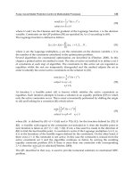
4.2 Effect of load disruptions and noise
In order to test the effect of load disruptions, we have added to the system output a constant
equals to 0.02 from iteration 100 to iteration 125 and from iteration 200 to iteration 225. And in
the case of noise, we have added to the output of the process an uncertain pseudo-noise of
maximal amplitude equal to 0.025. Figs. 6 and 7 present the evolutions of the set point, the
outputs obtained, respectively, with the presence of load disruption and noise. Fig. 6 shows the
evolutions of the set point, the outputs signals obtained with both NMPC and MAMPC control
strategy. It is clear from this figure that the presence of load disruptions, from iteration70 to
iteration 90 and from iteration 120 to iteration 140, does not lead to a correct pursuit. Thus, the
presence of load disruptions has more effect on NMPC control than the MAMPC strategy. Fig. 8
shows the evolutions of the set point, the outputs obtained with NMPC and MAMPC strategy.
According to the obtained results, we notice that the MAMPC controller is capable to deliver a
less fluctuate output than that obtained with NMPC approach.
0 50 100 150
0
1
2
3
4
5
6
7
samples
NMPC
MAMPC
setpoint
Fig. 6. Evolution of the set point, the output NMPC and MAMPC control in the case of load
disruptions.
Advanced Model Predictive Control
42
0 50 100 150
0
1
2
3
4
5
6
7
samples
NMPC
setpoint
MAMPC
Fig. 7. Evolution of the set point, the outputs NMPC and MAMPC control in the case of the
effect of the noise.
Fast Nonlinear Model Predictive Control using
Second Order Volterra Models Based Multi-agent Approach
43
4.3 Convex optimization approach
In order to avoid solving nonconvex optimization problem, MAMPC optimization
procedure, a method for convex NMPC was also developed in this chapter book. The
performance of the proposed controllers is evaluated by applying to the same process and
the attention has been focused on multi-agent model predictive control approach as a
possible way to resolve non-convex optimization tasks. We have shown in Figure 8, a new
constraint where the control is limited between 0 and .5. The nonlinear programming
algorithm (NLP) cannot find a solution for the optimization problem. So because of the use
of a nonlinear model, the NMPC calculation usually involves a non-convex nonlinear
program, for which the numerical solution is very challenging. Therefore, finding a global
optimum can be a difficult and computationally very demanding task, if possible at all. In
other words, non-convexity makes the solution of the NLP uncertain. The proposed
approach describe algorithm that find the solution of a non-convex programming.
Fig. 8. Evolution of the set point, the outputs NMPC and MAMPC control: Restriction
applicability of the NMPC