DESIGN PROCEDURE FOR PRESSURE VESSEL
Bạn đang xem bản rút gọn của tài liệu. Xem và tải ngay bản đầy đủ của tài liệu tại đây (3.04 MB, 106 trang )
TABLE OF CONTENTS
S. NO TITLE PAGE
NO
1. INTRODUCTION TO PRESSURE VESSELS
4
1.1. BASIC TERMINOLOGIES USED 5
1.2 CYLINDERS AND SPHERS 19
2. ANALYTICAL DESIGN OF METHANATOR
26
2.1 GIVEN DATA 28
2.2 REQUIRED DIMENTIONS OF METHANATOR 29
2.3 METHANATOR AS A THIN CYLINDER 30
2.4 THICKNESS OF SHELL 32
2.5 THICKNESS OF 2:1 ELLIPSOIDAL HEAD 34
1
2.6 OPENING IN THE PRESSURE VESSELS 35
2.7 SELECTION OF FLANGES 37
2.8 THICKNESS OF SKIRT OR DESIGN OF SUPPORTS 39
2.9 LOADINGS 44
2.10 STRESSES IN RESPONSE TO DIFFERENT LOADS 45
a) INTERNAL PRESSURE
45
b) WEIGHT 46
c) WIND LOAD 49
d) SEISMIC LOAD 54
2.11 COMBINATION OF STRESSES 57
2.12 COMPARISION 58
2.13 DESIGN OF ANCHOR BOLTS 58
2.14 WELDING OF PRESSURE VESSELS 62
3. ANALYSIS BY ANSYS
67
3.1 ANSYS 68
3.2 ANSYS INPUT METHODS 69
3.3 SHELL 51 70
3.4 ANALYSIS OF METHANATOR UNDER INTERNAL PRESSURE
USING SHELL 51 71
3.5 ANALYSIS OF METHANATOR TO COMMAND WINDOW 72
3.6 ANALYSIS OF METHANATOR THROUGH GUI 72
3.7 TO FIND THE HOOP AND LONGITUDINAL STRESS ON ANSYS 88
3.8 DISPLACEMENTS OF NODES 91
2
4. COMARISION AND CONCLUSION
92
4.1 MEMBRENE STRESSE IN METHANATOR 93
4.2 COMARISION OF ANSYS AND ANALYTICAL SOLUTION 94
4.3 CONCLUSION 96
REFERENCES
TABLES
3
INTRODUCTION
TO
PRESSUREVESSEL
S
4
1.1 BASIC TERIMINOLOGIES
USED
VESSEL:
A container or structural envelope in which materials are processed,
treated, or stored; for example, pressure vessel, reactor vessel, agitator
vessel, and storage vessels (tanks).
PRESSURE VESSEL:
A metal container generally cylindrical or spheroid, capable or
withstanding various loadings.
STRAIN:
Any forced change in the dimensions of a body. A stretch is a tensile
strain; a shortening is a compressive strain; an angular distortion is a shear
strain. The word strain is commonly used to connote unit strain.
STRESS:
Internal force exerted by either of two adjacent parts of a body upon
the other across an imagined plane of separation. When the forces are
parallel to the plane, the stress is called shear stress; when the forces are
normal to the plane the stress is called normal stress; when the normal stress
is directed toward the part on which it acts is called compressive stress;
when it is directed away from the part on which it acts it is called tensile
stress.
5
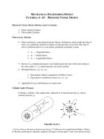
STRESSES IN PRESSURE VESSEL:
• Longitudinal S1 stress.
• Circumferential (hoop) S2 stress.
S1 and S2 called membrane (diaphragm) stress
For vessel having a figure of revolution
Bending stress
Shear stress
Discontinuity stress at an abrupt change in thickness or
Shape of the vessel
TENSILE STRENGTH:
The maximum stress a material subjected to a stretching load can
withstand without tearing.
TENSILE STRESS:
Stress developed by a material bearing tensile load.
TEST PRESSURE:
The requirements for determining the test pressure based on
calculations are out lined in UG-99(c) for the hydrostatic test and UG-100(b)
for the pneumatic test. The basis for calculated test pressure in either of
these paragraphs is the highest permissible internal pressure as determined
by the design formulas, for each element of the vessel using nominal
thickness with corrosion allowances included and using the allowable stress
values for the temperature of the test. (Code UA-60)
6
THERMAL STRESS:
A self-balancing stress produced by a non uniform distribution of
temperature or by differing thermal coefficients of expansion. Thermal stress
developed in a solid body whenever a volume of material is prevented from
assuming the size and shape that it normally should under a change in
temperature.
THICKNESS OF VESSEL WALL:
1. The “required thickness” is that computed by the formulas in this
division, before corrosion allowance is added.
2. The “design thickness” is the sum of the required thickness and the
corrosion allowance.
3. The “nominal thickness” is the thickness selected as commercially
available, and as supplied to the manufacturer; it may exceed the
design thickness.
UNIT STRAIN:
Unit tensile strain is the elongation per unit length; unit compressive
strain is the shortening per unit length; unit shear strain is the change in
angle (radians) between two lines originally at right angles to each other.
UNIT STRESS:
The amount of stress per unit of area.
7
WELD METAL:
The metal resulting from the fusion of base metal and the filler metal.
WELDING:
The metal joining process in making welds.
In the construction of vessels the welding process is restricted by the
code (UW-27) as follows;
1. Shielded metal arc, submerged arc, gas metal arc, gas tungsten arc,
atomic hydrogen metal arc, oxy fuel gas welding, electro-slag, and
electron beam.
2. Pressure welding process: flash, induction, resistance, pressure
Thermit, and pressure gas.
YIELD POINT:
The lowest stress at which strain increases without increase in stress.
For some purpose it is important to distinguish between the upper yield
point, which is the stress at which stress-stain curve first become horizontal,
and the lower yield point, which is the somewhat lower and almost constant
stress under which the metal continues to deform. Only a few materials
exhibit a true yield point; for some materials the term is sometimes used as
synonymous with yield strength.
SPECIFIC GRAVITY:
The ratio of the density of a material to the density of some standard
material, such as water at a specified temperature, for example, 4
°
C or 60°F.
Or (for gases) air at standard conditions of pressure and temperature.
8
STABILITY OF VESSEL:
(Elastic stability) The strength of the vessel to resist buckling or
wrinkling due to axial compressive stress. The stability of a vessel is
severely affected by out of roundness.
SHELL:
Structural element made to enclose some space. Most of the shells are
generated by the revolution of plane curve.
SHEAR STRESS:
The component of the stress tangent to the plane of reference.
RADIUS OF GYRATION:
The radius of gyration of an area with respect to given axis is the
square root of the quantity obtained by dividing the moment of inertia of the
area with respect to that axis by the area.
RESIDUAL STRESS:
Stress remaining in a structure or member as a result of thermal or
mechanical treatment, or both.
RESISTANCE WELDING:
A pressure welding process wherein the heat is produced by the
resistance to the flow of an electric current.
9
SECONDARY STRESS:
A normal stress or a shear stress developed by the constraint of
adjacent parts or by self-constraint of a structure. The basic characteristic of
a secondary stress is that it is self-limiting. Local yielding and minor
distortions can satisfy the conditions which cause the stress to occur and
failure from one application of the stress is not to be expected. Examples of
secondary stress are: general thermal stress; bending stress at a gross
structural discontinuity.
POISSONS’RATIO:
The ratio of lateral unit strain to longitudinal unit strain, under the
conditions of uniform and uniaxial longitudinal stress within the
proportional limit.
POSTWELD HEAT TREATMENT:
Heating a vessel to a sufficient temperature to relieve the residual
stresses which are the result of mechanical treatment and welding.
Pressure vessels and parts shall be post weld heat treated.
PREHEATING:
Heat applied to base metal prior to welding operations.
PRESSURE RELIEF VALVE:
10
A valve which relieves pressure beyond a specified limit and recluses
upon return to normal operating conditions.
PRESSURE WELDING:
A group of welding processes wherein the weld is completed by use
of pressure.
PRIMARY STRESS:
A normal or shear stress developed by the imposed loading which is
necessary to satisfy the simple laws of equilibrium of external and internal
forces and moments. The basic characteristic of a primary stress is that it is
not self-limiting. Primary stresses which considerably exceed the yield
strength will result in failure or at least, in gross distortion. A thermal stress
is not classified as primary stress. Primary membrane stress is divided into
local and general categories. A general primary membrane stress is one
which is so disturbed in the structure no redistribution of load occurs as a
result of yielding. Examples of primary stress are: general membrane in a
circular cylindrical or a spherical shell due to internal pressure or to
distributed live load; bending stress in the central portion of a flat head due
to pressure.
OPERATING PRESSURE:
The pressure at the top of a vessel at which it normally operates. It
shall not exceed the maximum allowable working pressure and it is usually
kept at a suitable level below the setting of the pressure relieving devices to
prevent their frequent opening. (Code UA-60)
OPERATING TEMPERATURE:
11
The temperature that will be maintained in the metal of the part of the
vessel being considered for the specified operation of the vessel. (Code UA-
60)
NEUTRAL AXIS:
The line of zero fiber stress in any given section of a member subject
to bending; it is the line formed by the intersection of the neutral surface and
the section.
MOMENT OF INERTIA OF AN AREA (SECOND MOMENT OF AN
AREA)
The moment of inertia of an area with respect to an axis is the sum of
the products obtained by multiplying each element of the area by the square
of its distance from the axis. The moment of inertia (I) for thin walled
cylinder about its transverse axis; I = Π r
3
t
Where
r = mean radius of cylinder
t = wall thickness
MODULUS OF ELASTICITY (YOUNG’S MODULUS):
12
The rate of change of unit tensile or compressive stress with respect
to unit tensile or compressive strain for the condition of uniaxial stress
within the proportional limit. For most, but not all materials, the modulus of
elasticity is same for tension and compression. For nonisotropic materials
such as wood, it is necessary to distinguish moduli of elasticity in different
directions.
MODULUS OF RIGIDITY:
The rate of change of unit shear stress with respect to unit shear strain,
for the condition of pure shear within the proportional limit.
MAXIMUM ALLOWABLE STRESS VALUE:
The maximum unit stress permissible for any specific material that
may be used in the design formulas given in the code. (UG-23)
MAXIMUM ALLOWABLE WORKING PRESSURE:
The maximum gage pressure permissible at the top of a completed
vessel in its operating position for a designed temperature. This pressure is
based on the weakest element of the vessel using nominal thickness
exclusives of allowances for corrosion and thickness required for loading
other than pressure. (Code UA-60)
MEMBRANE STRESS:
The component of normal stress which is uniform ally distributed and
equal to the average value of stress across the thickness of the section under
consideration.
13
ISOTROPIC:
Having same properties in all directions. In discussion pertaining to
strength of materials, isotropic usually means having the same strength and
elastic properties.
JOINT EFFICIENCY:
A numerical value expressed as the ratio of the strength of a riveted,
welded, or braze joint to the strength of the parent metal.
LOADING:
Loading (loads) are the results of various forces. The loadings to be
considered in designing a vessel : internal or external pressure, impact loads,
weight of the vessel, wind and earthquake, superimposed loads, local load,
effect of temperature gradients.(Code UG-22).
LOW-ALLOY STEEL:
A harden able carbon steel generally containing not more than about
1% carbon and one or more of the following components; ‹ (less than) 2%
manganese, ‹ 4%nickel, ‹ 2%chromium, 0.6% molybdenum, and
‹ 0.2%vanadium.
HEAT TREATMENT:
Heat treating operation performed either to produce changes in
mechanical properties of the material or to restore its maximum corrosion
14
resistance. There are three principle types of heat treatment; annealing,
normalizing, and post weld heat treatment
.
HYDROSTATIC TEST:
The completed vessel filled with water shall be subjected to test
pressure which is equal to 1 ½ times the maximum allowable working
pressure to be marked on the vessel or 1 ½ the design pressure by
agreement between the user and the manufacturer. (Code UG-99)
IMPACT STRESS:
Force per unit area imposed to a material by a suddenly applied force.
IMPACT TEST:
Determination of the degree of resistance of a material to breaking by
impact, under bending, tensile and torsion loads, the energy absorbed is
measured by breaking the material by a single blow.
GAGE PRESSURE:
The amount by which the total absolute pressure exceeds the ambient
atmospheric pressure.
FILLER METAL:
Material to be added in making a weld.
FIBER STRESS:
A term used for convenience to denote the longitudinal tensile or
compressive stress in a beam or other member subject to bending. It is
15
sometimes used to denote this stress at the point or points most remote from
the neutral axis, but the term stress in extreme fiber is preferable for this
purpose. Also, for convenience, the longitudinal elements or filaments of
which a beam may be imagined as composed are called fibers.
FACTOR OF SAFETY:
The ratio of the load that would cause a failure of a member or
structure, to the load that is imposed upon it in service.
FATIGUE:
Tendency of materials to fracture under many repetitions of a stress
considerably less than the ultimate static strength.
ECENTRICITY:
A load or component of a load normal to a given cross section of a
member is eccentric with respect to that section if it does not act through
centroid. The perpendicular distance from the line of action of the load to
either of principle central axis is the eccentricity with respect to that axis.
EFFICIENCY OF A WELDED JOINT:
The efficiency of the welded joint is expressed as a numerical quantity
and is used in the design of a joint as a multiplier of the appropriate
allowable stress value. (Code UA-60)
ELASTIC:
16
Capable of sustaining stress without permanent deformation; the term
is also used to denote conformity to the law stress-strain proportionality. An
elastic stress or elastic strain is a stress or strain within the elastic limit.
ELASTIC LIMIT:
The least stress that will cause permanent set.
DESIGN PRESSURE:
The pressure used in determining the minimum permissible thickness
or physical characteristics of the different parts of the vessel. (Code UG-60)
DESIGN TEMPERATURE:
The mean metal temperature (through the thickness) expected under
operating conditions for the part considered. (Code UG-20)
CREEP:
Continuous increase in deformation under constant or decreasing
stress. The term is usually with reference to the behavior of metal under
tension at elevated temperatures. The similar yielding of a material under
compressive stress is usually called plastic flow or flow.
CORROSION:
Chemical erosion by motionless or moving agents. Gradual
destruction of a metal or alloy due to chemical process such as oxidation or
action of a chemical agent.
17
CLAD VESSEL:
A vessel made from plate having a corrosion resistant material
integrally bonded to a base of a less resistant material. (Code UA-60)
ALLOY:
Any of a large no. of substances having metallic properties consisting
of two or more elements; with few exceptions, the components are usually
metallic elements.
18
1.2 CYLINDERS AND
SPHERES:
Vessels such as steam boilers, air compressors, storage tanks,
accumulators and large pipes are subjected to internal fluid pressure which is
uniformly distributed. All the above mentioned vessels are classified as
cylinders or spheres.
THIN CYLINDER:
If the ratio of the thickness to the internal diameter i.e. t/d is less than
about 1/20, the cylinder is assumed to be thin cylinder.
THICK CYLINDER:
If the ratio of thickness to the internal diameter i.e. t/d is greater than
1/20, the cylinder is assumed to be thick cylinder.
STRESSES IN CYLINDERS:
The following stresses are illustrated in fig. (1) and fig. (2)
19
CIRCUMFERENTIAL OR HOOP STRESS:
The stress which acts tangent to the circumference and perpendicular
to the axis of the cylinder is called circumferential or hoop stress. It is
denoted by f
h.
LONGITUDINAL STRESS:
The stress which acts normal to circumference and parallel to the axis
of the cylinder is called longitudinal stress. It is denoted by f
l
.
20
RADIAL STRESS:
The stress which acts in a direction perpendicular to the internal
surface is called radial stress. It is denoted by f
r
. Radial stress is very small
as compared to f
l
and f
h
in case of thin cylinder and is therefore ignored.
ANALYSIS OF THIN CYLINDER:
Consider the equilibrium of half cylinder of length ‘L’ sectioned
through a diameteral plane as shown in fig, (3)
Let the internal diameter be‘d’ and the thickness ‘t’; ‘p’ is the applied
internal pressure, fh the hoop stress and fl the longitudinal stress.
HOOP STRESS:
Consider the elemental ring of the cylinder subtending an angle δθ.
Let ds = arc length of elemental ring = r.
Force acting on elemental ring = p *area
21
= prδθL
Vertical component of this force = prδθL Sinθ
Total vertical force =prL
0
∫
180
Sinθδθ
= -prl (cos 180 – Cos 0) = 2prL
= pdL eq.(1)
But
dL = horizontal projected area.
So
Total vertical force = pdL = intensity of pressure * horizontal
projected area.
This force tries to burst the cylinder into two halves and is called
‘bursting force’.
Bursting force = F = pdL
And
Resisting force = stress * resisting area
= f
h
* 2tL
For equilibrium of cylinder
Bursting force = Resisting force
pdL = f
h
*2tL
f
h
= pd/2t eq.(A)
LONGTUDINAL STRESS:
Cross sectional area =Π /4 d
2
Total force at the end of cylinder = p* Π/4 d
2
22
This force tries to burst the cylinder at the ends of cylinder and is
called ‘bursting force’.
Bursting force = F = p* Π/4 d
2
Resisting force = stress * resisting area
= f
l
* Πdt
for equilibrium of cylinder
Bursting force = resisting force
P* Π/4 d
2
= f
l
* Πdt
F
l
= pd/4t eq. (B)
Comparing (A) and (B)
F
l
=1/2 f
h
THIN SPHERICAL SHELL:
In case of spherical shell also, the radial stress will be neglected and
the circumferential or hoop stress will be assumed to be constant.
As shown in the fig. the two stresses are equal to due to symmetry. i.e.
f
h
= f
l
= f
23
Cross-sectional area = Π /4d
2
Bursting force = p* Π /4d
2
Resisting force = stress * resisting area
= f * dt
For equilibrium of shell
Bursting force = resisting force
P * Π /4d
2
= f * dt
f = pd/4t
CYLINDERICAL SHELL WITH HEMISPHERICAL ENDS:
As shown in the fig. let t
1
be the thickness of the cylinder and t
2
be the
thickness of the hemisphere, the internal diameter being assumed the same
for both.
STRESSES IN THE CYLINDERICAL PORTION:
If the shell is subjected to an internal pressure p, stresses in the
cylinder will be;
Hoop stress, f
h
= pd/2t
1
24
And
Longitudinal stress, f
l
=pd/4t
1
Hoop strain,Є
h
= f
h
/E – ν f
l
/E = 1/E (f
h
– ν f
l
)
=1/E (pd/2t
1
- pd/4t
1
) = 1/E ((2pd - pd/4t
1
))
Є
h
= pd/4t
1
E (2 - ν)
Longitudinal strain, Є
l
= f
l
/E - fh/E = pd/4t
1
E - pd/2t
1
Є
l
= pd/4t
1
E (1 – 2ν)
STRESSES IN THE SPHRICAL PORTION:
For the hemispherical ends having thickness t
2,
we have
f
h
΄
= f
l
΄
= f = pd/4t
2
Therefore, hoop stress, f
h
= pd/4t
2
And
Longitudinal stress, f
l
= pd/4t
2
Then
Hoop strain, Є
h
΄
= f
h
/E – f
l
/E = pd/4t
2
E – pd/4t
2
E
Є
h
΄
= pd/4t
2
E (1 -ν)
Longitudinal strain,Є
l
΄
= f
l
΄
/E - ν f
h
΄
/E = pd/4t
2
E - νpd/4t
2
E
Є
l
΄
= pd/4t
2
E (1 -ν)
Therefore for spherical portion
Є
h
΄ = Є
l
΄
At the junction of cylindrical and spherical portion
Є
h
= Є
h
΄
Pd/4t
1
E (2 -ν) = pd/4t
2
E (1 -ν)
t
2
/t
1
= (1 -ν )/(2 -ν )
25