07 electure friction stir welding
Bạn đang xem bản rút gọn của tài liệu. Xem và tải ngay bản đầy đủ của tài liệu tại đây (212.56 KB, 10 trang )
Friction Stir Welding
Introduction
Friction stir welding (FSW) was invented and patented by TWI in 1991. It is a solid state welding process that uses a non-
consumable rotating tool to heat, plasticise and join two material pieces together.
the FSW process (as all friction welding of metals) takes place in the solid phase below the melting point of the materials to be
joined. The benefits therefore include the ability to join materials which are difficult to fusion weld, for example 2000 and 7000
aluminium alloys.
Friction stir welding can use purpose-designed equipment or modified existing machine tool technology. The process is also
suitable for automation and adaptable for robot use.
Friction Stir Welding
Principle
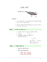
A friction stir weld, is formed by plunging a rotating shouldered pin tool, with a pin length slightly less than the weld depth
required, into the faying faces until the tool shoulder is in intimate contact with the work surface and then moving the work
against the pin, or vice-versa.
The rotating pin within the workpiece friction heats the metal and produces a plasticised tubular shaft of metal around the pin. As
the pin is moved in the direction of welding the leading face of the pin, assisted by a special pin profile, forces plasticised
material to the back of the pin whilst applying a substantial forging force to consolidate the weld metal.
Friction Stir Welding
Advantages
•
Low distortion, even in long welds
• Excellent mechanical properties as proven by fatigue, tensile and bend tests
• No fume
• No porosity
• No spatter
• Low shrinkage
• Can operate in all positions
• Energy efficient
• Non-consumable tool
• One tool can typically be used for up to 1000m of weld length in 6000 series
aluminium alloys
• No filler wire
• No gas shielding for welding aluminium
• No welder certification required
• Some tolerance to imperfect weld preparations - thin oxide layers can be accepted
• No grinding, brushing or pickling required in mass production
• Can weld aluminium and copper of >50mm thickness in one pass.
Friction Stir Welding
Limitations
The limitations of the FSW process are being reduced by intensive research and
development. However, the main limitations of the FSW process are at present:
• Workpieces must be rigidly clamped
• Backing bar required (except where self-reacting tool or directly opposed tools are used)
• Keyhole at the end of each weld
• Cannot make joints which required metal deposition (e.g. fillet welds)
Friction Stir Welding
Joints
a) Square butt;
b) Combined butt and lap;
c) Single lap;
d) Multiple lap;
e) 3 piece T butt;
f) 2 piece T butt;
g) Edge butt;
h) Possible extrusion design to enable corner fillet weld to be made.
Friction Stir Welding
Friction Stir Welding - Materials and thicknesses
Friction stir welding can be used for joining many types of materials and material
combinations, if tool materials and designs can be found which operate at the forging
temperature of the workpieces.
For aluminium alloys, the following alloys are easily welded. Maximum thickness in a single pass is dependent on machine power, but
values 50mm are achievable.
• 2000 series aluminium (Al-Cu)
• 5000 series aluminium (Al-Mg)
• 6000 series aluminium (Al-Mg-Si)
• 7000 series aluminium (Al-Zn)
• 8000 series aluminium (Al-Li)
Friction Stir Welding
Friction Stir Welding - Materials and thicknesses
MMCs based on aluminium (metal matrix composites)
Other aluminium alloys of the 1000 (commercially pure), 3000 (Al-Mn) and 4000 (Al-Si) series, aluminium castings.
Other materials successfully welded include:
• Copper and its alloys (up to 50mm in one pass)
• Lead
• Titanium and its alloys
• Magnesium alloys
• Zinc
• Plastics
• Mild steel
• Stainless steel (austenitic, martensitic and duplex)
• Nickel alloys
Friction Stir Welding
Friction Stir Welding – Microstructures
A friction stir weld is divided into distinct zones
as shown in figure
Friction Stir Welding
Friction Stir Welding – Microstructures
A friction stir weld is divided into
distinct zones as shown in figure
B-Heat affected zone (HAZ): the material has experienced a thermal cycle which has modified the microstructure and/or the mechanical
properties. However, there is no plastic deformation occurring in this area.
C-Thermo-mechanically affected zone (TMAZ): In this region, the material has been plastically deformed by the friction stir welding tool,
and the heat from the process will also have exerted some influence on the material
In the case of aluminium, it is possible to get significant plastic strain without recrystallisation in this region, and there is generally a
distinct boundary between the recrystallised zone and the deformed zones of the TMAZ.
In other materials, the distinct recrystallised region (the nugget) is absent, and the whole of the TMAZ appears to be recrystallised.
D- Weld Nugget: The recrystallised area in the TMAZ in aluminium alloys has traditionally been called the nugget.
Friction Stir Welding
Example Applications
Shipbuilding and marine industries
• Panels for decks, sides, bulkheads and floors
• Aluminium extrusions
• Hulls and superstructures
• Helicopter landing platforms
• Offshore accommodation
• Marine and transport structures
• Masts and booms, e.g. for sailing boats
• Refrigeration plant
Aerospace industry
•
Wings, fuselages, empennages
• Cryogenic fuel tanks for space vehicles
• Aviation fuel tanks
• External throw away tanks for military aircraft
• Military and scientific rockets
• Repair of faulty MIG welds
Other industries: Railways, LandTransportation etc