TCAD ready density gradient calculation of channel charge for strained sistrained si 1− x ge x dual channel pMOSFETs on (001) relaxed si 1− y ge y
Bạn đang xem bản rút gọn của tài liệu. Xem và tải ngay bản đầy đủ của tài liệu tại đây (149.51 KB, 18 trang )
Title
TCAD ready density gradient calculation of channel charge for
Strained Si/Strained Si1−xGex dual channel pMOSFETs on
(001) Relaxed Si1−y Gey
C. D. Nguyen, A. T. Pham, C. Jungemann, and B. Meinerzhagen
Institut fă
ur Netzwerktheorie und Schaltungstechnik
Technische Universită
at Braunschweig
C. Jungemann
IWCE 2004
1
Outline
ã Motivation
ã Schră
odinger/Poisson Solver for Strained Si and SiGe
ã Density Gradient Model
• Extraction of the heterojunction valence band offsets needed for TCAD
simulators
• Conclusion and Outlook
C. Jungemann
IWCE 2004
2
Motivation
C. Jungemann
IWCE 2004
3
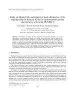
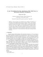
Motivation
multi stacked strained structure
Vg
0
SiO2 (4.4nm)
✁
✁
✁
✁
✁
✁
✁
✁
✁
✁
✁
✁
✁
Strained Si0.4 Ge0.6
(5nm)
✁
Strained Si (3.3nm)
III
III/II
∆EV
II
II/I
∆EV
I
Relaxed Si0.7 Ge0.3
EV
EF
EC
Changes in the band structure and small
thickness of the strained layers
= Size Quantization
Solution: Schră
odinger equation (SE)
with a full band description using the
k · p-method
For TCAD use, directly solving the SE
is too CPU intensive.
=⇒ Density Gradient Method (DGM)
Problem: unknown model parameters
e. g. effective band offsets.
z
Vb
C. Jungemann
IWCE 2004
4
Motivation
Effective band offsets can be determined by:
• Measurement: The effective band offsets can be extracted by inverse
modeling of CV measurements based on the DGM [1].
=⇒ Uncertainty due to incomplete knowledge of the investigated devices
• Simulation: Based on the self-consistent solution of the SE and Poisson
equations, the effective band offsets can be extracted and the errors of
the DGM approximation can be investigated.
[1] C. Ni Chleirigh et al., “Extraction of band offsets in Strained Si/Strained SiGe on relaxed
SiGe dual-channel enhanced mobility structures” to be presented at SiGe Materials, Processing
and Devices Symposium, Hawai, 2004.
C. Jungemann
IWCE 2004
5
Schră
odinger/Poisson Solver for Strained Si and SiGe
C. Jungemann
IWCE 2004
6
Schră
odinger/Poisson Solver for Strained Si and SiGe
6 ì 6 k · p SE for holes:
∂
n
+ ˆI · eV (z) Fn
k (z) = En (k)Fk (z)
∂z
ˆ =H
ˆ kp + H
ˆ so + H
ˆ str and
with k = (kx, ky ), H
ˆ k, kz = −i
H
V (z) = Ψ(z) + ∆Evav/e,
∆Evav [2]: “natural” valance band offset step of the Si/ SiGe heterostructure.
The quantum-mechanical charge density:
pqm(z) =
1
2
n (2π)
|Fkn|2f (En(k) + EF ) d2k ,
(1)
In contrast to nextnano3, a modified discretization scheme for the twodimensional k space is used in order to reduce the computation time and
to calculate (1) with high accuracy. Moreover, the CV characteristics for
mobility and band-offset extraction are determined by 1st order perturbation
theory. =⇒ About 30 times less CPU intensive than nextnano.
[2] C. G. van de Wall Phys. Rev. B, vol. 35, no. 15, pp. 8154–8165, 1987
C. Jungemann
IWCE 2004
7
Schră
odinger/Poisson Solver for Strained Si and SiGe
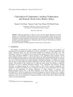
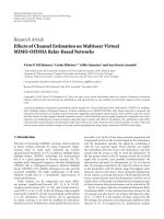
New interpolation method and grid
0.378
0.40
0.376
0.35
k||=0.2 [π/a0,Si]
Energy [eV]
Energy [eV]
0.374
0.372
0.370
Nφ=45
0.368
0.366
φ=00
0.30
0.25
0.20
0.15
Nk||=45
Nφ=8, linear inter.
0.10
Nk||=8, linear inter.
Nφ=8, harmonic inter.
0.05
Nk||=8, cubic spline inter.
0.364
0
0
5
10
15
20
25
30
35
40
45
0
0.1
0.2
o
φ[ ]
=⇒
C. Jungemann
0.3
0.4
Si
k|| [π/a0 ]
0.5
0.6
CPU-time gain = 25-30
IWCE 2004
8
Schră
odinger/Poisson Solver for Strained Si and SiGe
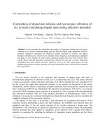
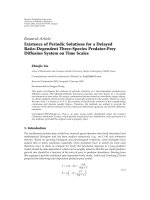
Band structure of first three subbands (ND = 5 × 1017 cm−3, VG = −2.5V,
φ = 0o) and the wave function of the first energy level.
1.0
1. subband
2. subband
3. subband
0.9
0.8
0.4
1,1
F0 (z)
strained Si0.4Ge0.6
strained Si
0.7
0.6
Energy [eV]
Energy [eV]
0.3
relaxed
Si0.7Ge0.3
0.5
0.4
0.2
0.3
0.1
0.2
a)
0.1
0
0.0
0.1
0.2
C. Jungemann
0.3
0.4 0.5 0.6
Si
k|| [ π /a0 ]
0.7
0.8
0.9
1
2
3
4
5
6
7
8
9
10
1.0
IWCE 2004
9
Schră
odinger/Poisson Solver for Strained Si and SiGe
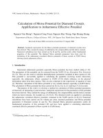
Hole density at room temperature for two gate biases evaluated by SE
50
FBSC (VG=-4V)
FBSC (VG=-2V)
Hole density [x10
18
-3
cm ]
40
30
20
10
0
C. Jungemann
0
1
2
3
4
5
z [nm]
6
7
IWCE 2004
8
9
10
10
Density Gradient Model
C. Jungemann
IWCE 2004
11
Density Gradient Model
Approximate quantum correction by the density gradient model (DGM):
p
dg
(z) = Nv exp
Ev + Φm + Λ − EF
.
kB T
Here, Φm = (3/2)kB T log(m∗) and Λ is obtained by solving a differential equation:
2γ
¯ − EF
¯ − EF
1
Φ
Φ
∇·∇
+
∇
Λ=
12m
kB T
2
kB T
C. Jungemann
2
¯ = Ev + Φm + Λ
, with Φ
IWCE 2004
13
Density Gradient Model
What is new in strained material compared to relaxed material?
✁
✁
✁
✁
Electrons:
∆Ec(y) known from literature.
✁
✁
✁
✁
✁
✁
✁
✁
∆Ec(y)
✁
✁
✁
✁
✁
✁
✁
✁
✁
✁
✁
✁
✁
✁
✁
✁
∆Ev (y, k||)
✁
✁
tSSi
C. Jungemann
Relaxed Si1−y Gey
Holes:
∆Ev (y, k||) depends on k||
¯v (y) independent from k||
but ∆E
required for TCAD (effective valence band offsets)
IWCE 2004
14
Extraction of the band offsets for TCAD
C. Jungemann
IWCE 2004
14
Extraction of the band offsets for TCAD
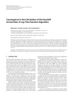
20
Cgd[pF]
15
10
I/II
∆Ev
I/II
∆Ev
+ 40meV
- 40meV
I/II
5
ana. ∆Ev
Ii/III
∆Ev
II/III
∆Ev
0
-4
C. Jungemann
-3
II/III
and ∆Ev
- 40 meV
+ 40 meV
-2
VG[V]
-1
0
• Based on the CV data calculated by
SE, the valance band offsets have
been extracted by matching the CV
data calculated by DGM.
• The conduction band offsets are
fixed during the fitting procedure.
• Note that in this version the effective mass of Si for DGM was used
because no values are available for
strained Si and strained SiGe.
IWCE 2004
15
Extraction of the band offsets for TCAD
Gate capacitance with different thickness of strained Si region (T = 300 K)
20
20
DGM
FBSC
DGM
FBSC
15
Cgd[pF]
Cgd[pF]
15
10
5
0
-4
10
5
-3
-2
VG[V]
-1
0
0
-4
tSSi = 3.3 [nm]
C. Jungemann
-3
-2
VG[V]
-1
0
tSSi = 4.0 [nm]
IWCE 2004
16
Conclusion and Outlook
C. Jungemann
IWCE 2004
17
Conclusion and Outlook
• Conclusions
– Efficient evaluation of low frequency CV characteristic for multi stacked
strained Si structures with a complete description of the valance band
structure is now possible.
– Accurate calculation of CV-characteristics for strained Si/SiGe dual
channel pMOSFETs based on Density Gradient Method with the corresponding extracted valance band offsets.
• Outlook
– Improvement of the state of art Density Gradient Model for holes in
strained Si and strained Si1−xGex based on our SE/PE solver.
– Extraction of the heterojunction valence band offsets and other parameters for wide range of Ge contents.
– Verification of the extracted results by comparison with measured CVdata.
C. Jungemann
IWCE 2004
18