Air conditioning and refrigeration mechanical engineering handbook
Bạn đang xem bản rút gọn của tài liệu. Xem và tải ngay bản đầy đủ của tài liệu tại đây (1.58 MB, 161 trang )
Wang, S.K. and Lavan, Z. “Air-Conditioning and Refrigeration”
Mechanical Engineering Handbook
Ed. Frank Kreith
Boca Raton: CRC Press LLC, 1999
c
1999byCRCPressLLC
9
-1
© 1999 by CRC Press LLC
Air-Conditioning and
Refrigeration
9.1 Introduction 9-2
Air-conditioning • Air-Conditioning Systems • Air-
Conditioning Project Development and System Design
9.2 Psychrometrics 9-11
Moist Air • Humidity and Enthalpy • Moist Volume, Density,
Specific Heat, and Dew Point • Thermodynamic Wet Bulb
Temperature and Wet Bulb Temperature • Psychometric Charts
9.3 Air-Conditioning Processes and Cycles 9-18
Air-Conditioning Processes • Space Conditioning, Sensible
Cooling, and Sensible Heating Processes • Humidifying and
Cooling and Dehumidifying Processes • Air-Conditioning
Cycles and Operating Modes
9.4 Refrigerants and Refrigeration Cycles 9-34
Refrigeration and Refrigeration Systems • Refrigerants,
Cooling Mediums, and Absorbents • Classification of
Refrigerants • Required Properties of Refrigerants • Ideal
Single-Stage Vapor Compression Cycle • Coefficient of
Performance of Refrigeration Cycle • Subcooling and
Superheating • Refrigeration Cycle of Two-Stage Compound
Systems with a Flash Cooler • Cascade System Characteristics
9.5 Outdoor Design Conditions and Indoor
Design Criteria 9-48
Outdoor Design Conditions • Indoor Design Criteria and
Thermal Comfort • Indoor Temperature, Relative Humidity,
and Air Velocity • Indoor Air Quality and Outdoor Ventilation
Air Requirements
9.6 Load Calculations 9-54
Space Loads • Moisture Transfer in Building Envelope •
Cooling Load Calculation Methodology • Conduction Heat
Gains • Internal Heat Gains • Conversion of Heat Gains into
Cooling Load by TFM • Heating Load
9.7 Air Handling Units and Packaged Units 9-65
Terminals and Air Handling Units • Packaged Units • Coils •
Air Filters • Humidifiers
9.8 Refrigeration Components and
Evaporative Coolers 9-76
Refrigeration Compressors • Refrigeration Condensers •
Evaporators and Refrigerant Flow Control Devices •
Evaporative Coolers
Shan K. Wang
Individual Consultant
Zalman Lavan
Professor Emeritus, Illinois
Institute of Technology
9
-2
Section 9
© 1999 by CRC Press LLC
9.9Water Systems 9-87
Types of Water Systems • Basics • Water Piping • Plant-
Building Loop • Plant-Distribution-Building Loop
9.10Heating Systems 9-95
Types of Heating Systems
9.11Refrigeration Systems 9-103
Classifications of Refrigeration Systems
9.12Thermal Storage Systems 9-114
Thermal Storage Systems and Off-Peak Air-Conditioning
Systems • Ice-Storage Systems • Chilled-Water Storage
Systems
9.13Air System Basics 9-120
Fan-Duct Systems • System Effect • Modulation of Air Systems
• Fan Combinations in Air-Handling Units and Packaged Units
• Fan Energy Use • Year-Round Operation and Economizers •
Outdoor Ventilation Air Supply
9.14Absorption Systems 9-130
Double-Effect Direct-Fired Absorption Chillers • Absorption
Cycles, Parallel-, Series-, and Reverse-Parallel Flow
9.15Air-Conditioning Systems and Selection 9-135
Basics in Classification • Individual Systems • Packaged
Systems • Central Systems • Air-Conditioning System
Selection • Comparison of Various Systems • Subsystems •
Energy Conservation Recommendations
9.16Desiccant Dehumidification and
Air-Conditioning 9-152
Introduction • Sorbents and Desiccants • Dehumidification •
Liquid Spray Tower • Solid Packed Tower • Rotary Desiccant
Dehumidifiers • Hybrid Cycles • Solid Desiccant Air-
Conditioning • Conclusions
9.1 Introduction
Air-Conditioning
Air-conditioning
is a process that simultaneously conditions air; distributes it combined with the outdoor
air to the conditioned space; and at the same time controls and maintains the required space’s temperature,
humidity, air movement, air cleanliness, sound level, and pressure differential within predetermined
limits for the health and comfort of the occupants, for product processing, or both.
The acronym HVAC&R stands for heating, ventilating, air-conditioning, and refrigerating. The com-
bination of these processes is equivalent to the functions performed by air-conditioning.
Because I-P units are widely used in the HVAC&R industry in the U.S., I-P units are used in this
chapter. A table for converting I-P units to SI units is available in Appendix X of this handbook.
Air-Conditioning Systems
An
air-conditioning
or
HVAC&R system
consists of components and equipment arranged in sequential
order to heat or cool, humidify or dehumidify, clean and purify, attenuate objectionable equipment noise,
transport the conditioned outdoor air and recirculate air to the conditioned space, and control and maintain
an indoor or enclosed environment at optimum energy use.
The types of buildings which the air-conditioning system serves can be classified as:
• Institutional buildings, such as hospitals and nursing homes
• Commercial buildings, such as offices, stores, and shopping centers
Air-Conditioning and Refrigeration
9
-3
© 1999 by CRC Press LLC
•Residential buildings, including single-family and multifamily low-rise buildings of three or fewer
stories above grade
•Manufacturing buildings, which manufacture and store products
Types of Air-Conditioning Systems
In institutional, commercial, and residential buildings, air-conditioning systems are mainly for the
occupants’ health and comfort. They are often called
comfort air-conditioning systems
. In manufacturing
buildings, air-conditioning systems are provided for product processing, or for the health and comfort
of workers as well as processing, and are called
processing air-conditioning systems
.
Based on their size, construction, and operating characteristics, air-conditioning systems can be
classified as the following.
Individual Room or Individual Systems.
An individual air-conditioning system normally employs
either a single, self-contained, packaged room air conditioner (installed in a window or through a wall)
or separate indoor and outdoor units to serve an individual room, as shown in Figure 9.1.1. “Self-
contained, packaged” means factory assembled in one package and ready for use.
Space-Conditioning Systems or Space Systems.
These systems have their air-conditioning—cooling,
heating, and filtration—performed predominantly in or above the conditioned space, as shown in Figure
9.1.2. Outdoor air is supplied by a separate outdoor ventilation system.
Unitary Packaged Systems or Packaged Systems.
These systems are installed with either a single self-
contained, factory-assembled packaged unit (PU) or two split units: an indoor air handler, normally with
ductwork, and an outdoor condensing unit with refrigeration compressor(s) and condenser, as shown in
Figure 9.1.3. In a packaged system, air is cooled mainly by direct expansion of refrigerant in coils called
DX coils and heated by gas furnace, electric heating, or a heat pump effect, which is the reverse of a
refrigeration cycle.
Central Hydronic or Central Systems.
A central system uses chilled water or hot water from a central
plant to cool and heat the air at the coils in an air handling unit (AHU) as shown in Figure 9.1.4. For
energy transport, the heat capacity of water is about 3400 times greater than that of air. Central systems
are built-up systems assembled and installed on the site.
Packaged systems are comprised of only air system, refrigeration, heating, and control systems. Both
central and space-conditioning systems consist of the following.
Air Systems.
An air system is also called an air handling system or the air side of an air-conditioning
or HVAC&R system. Its function is to condition the air, distribute it, and control the indoor environment
according to requirements. The primary equipment in an air system is an AHU or air handler; both of
these include fan, coils, filters, dampers, humidifiers (optional), supply and return ductwork, supply
outlets and return inlets, and controls.
FIGURE 9.1.1
An individual room air-conditioning system.
Supply
outlet
Room air
conditioner
Return
grille
9
-4
Section 9
© 1999 by CRC Press LLC
Water Systems.
These systems include chilled water, hot water, and condenser water systems. A water
system consists of pumps, piping work, and accessories. The water system is sometimes called the water
side of a central or space-conditioning system.
Central Plant Refrigeration and Heating Systems.
The refrigeration system in the central plant of a
central system is usually in the form of a chiller package with an outdoor condensing unit. The
refrigeration system is also called the refrigeration side of a central system. A boiler and accessories
make up the heating system in a central plant for a central system, and a direct-fired gas furnace is often
the heating system in the air handler of a rooftop packaged system.
Control Systems.
Control systems usually consist of sensors, a microprocessor-based direct digital
controller (DDC), a control device, control elements, personal computer (PC), and communication
network.
Based on Commercial Buildings Characteristics 1992, Energy Information Administration (EIA) of
the Department of Energy of United States in 1992, for commercial buildings having a total floor area
FIGURE 9.1.2
A space-conditioning air-conditioning system (fan-coil system).
2
Chilled
water pump
Centrifugal
refrigeration
system
Condenser
pumps
Condenser
water system
Conditioned
space
Electric
heater
T2
2
1
Conditioned
space
T1
1
1 4 3
Outdoor
air
3
DDC
panel
Make-up air
AHU (outdoor
ventilation air)
T3
3
3
4
5
Fan-coil
Fan-coil
terminal
Chilled
water
system
Air-Conditioning and Refrigeration
9
-5
© 1999 by CRC Press LLC
FIGURE 9.1.3
A packaged air-conditioning system.
Outdoor
air
Mixing
box
DX-coil
Supply
duct
Condensing
unit
Heating
coil
Recirculating air
Air system
Ceiling diffuser
Supply
air
Return
grille
DDC controller
(control system)
Rooftop
packaged unit
Condensing
unit
Refrigeration
system
Air handler
(air system)
DX-coil
Return
grille
Outdoor
air
Supply
fan
Filter
Supply
fan
Worship hall
1
T1
9
-6
Section 9
© 1999 by CRC Press LLC
of 67,876 million ft
2
, of which 57,041 million ft
2
or 84% is cooled and 61,996 million ft
2
or 91% is
heated, the air-conditioning systems for cooling include:
Individual systems 19,239 million ft
2
(25%)
Packaged systems 34,753 million ft
2
(49%)
Central systems 14,048 million ft
2
(26%)
Space-conditioning systems are included in central systems. Part of the cooled floor area has been
counted for both individual and packaged systems. The sum of the floor areas for these three systems
therefore exceeds the total cooled area of 57,041 million ft
2
.
FIGURE 9.1.4a
A central air-conditioning system: schematic diagram.
AHU3 AHU4
AHU2AHU1
L1
L2
L3
Refrigeration
machine
Refrigeration
system
(a)
Water
system
Chilled
water
CHW
18
17
16
15
Air system
36
35
Condenser
water
Air-Conditioning and Refrigeration
9
-7
© 1999 by CRC Press LLC
Air-Conditioning Project Development and System Design
The goal of an air-conditioning/HVAC&R system is to provide a healthy and comfortable indoor
environment with acceptable indoor air quality, while being energy efficient and cost effective.
ASHRAE Standard 62-1989 defines
acceptable indoor air quality
as “air in which there are no known
contaminants at harmful concentrations as determined by cognizant authorities and with which a sub-
stantial majority (80% or more) of the people exposed do not express dissatisfaction.”
The basic steps in the development and use of an air-conditioning project are design, installation,
commissioning, operation, and maintenance. There are two types of air-conditioning projects:
design-
bid
and
design-build
. A design-bid project separates the design (engineering consultant) and installation
(contractors) responsibilities. In a design-build project, the design is also done by the installation
contractor. A design-build project is usually a small project or a project having insufficient time to go
through normal bidding procedures.
In the building construction industry, air-conditioning or HVAC&R is one of the
mechanical services
;
these also include plumbing, fire protection, and escalators.
Air-conditioning design
is a process of selecting the optimum system, subsystem, equipment, and
components from various alternatives and preparing the drawings and specifications. Haines (1994)
summarized this process in four phases: gather information, develop alternatives, evaluate alternatives,
FIGURE 9.1.4b
A central air-conditioning system: air and control systems for a typical floor.
Slot
diffuser
Fan-powered
box
1
8
TD
Electric
heating coil
Fan-powered
box
C
T
C
T
Return
slot
Conditioned spaceRiser
Interior zone Perimeter zone
Control system
1
2
3
4
5
6
7
8
1
2
3
4
5
6
7
DDC
panel
T
1
F
2
M
1
P
3
Filter
4
M
2
S
5
F
6
T
Cooling
coil
Supply
fan
5
4
M
M
7
S M
6
M
3
7
AHUReturn
fan
C
T
M
F
S
P
=
=
=
=
=
=
Controller
Temperature sensor
Motor
Velocity sensor
Switch
Static pressure sensor
9
-8
Section 9
© 1999 by CRC Press LLC
and sell the best solution. Design determines the basic operating characteristics of a system. After an
air-conditioning system is designed and constructed, it is difficult and expensive to change its basic
characteristics.
The foundation of a successful project is teamwork and coordination between designer, contractor,
and operator and between mechanical engineer, electrical engineer, facility operator, architect, and
structural engineer.
Field experience is helpful to the designer. Before beginning the design process it is advisable to visit
similar projects that have operated for more than 2 years and talk with the operator to investigate actual
performance.
Mechanical Engineer’s Responsibilities
The normal procedure in a design-bid construction project and the mechanical engineer’s responsibilities
are
1. Initiation of a project by owner or developer
2. Organizing a design team
3. Determining the design criteria and indoor environmental parameters
4. Calculation of cooling and heating loads
5. Selection of systems, subsystems, and their components
6. Preparation of schematic layouts; sizing of piping and ductwork
7. Preparation of contract documents: drawings and specifications
8. Competitive biddings by various contractors; evaluation of bids; negotiations and modifications
9. Advice on awarding of contract
10. Monitoring, supervision, and inspection of installation; reviewing shop drawings
11. Supervision of commissioning
12. Modification of drawings to the as-built condition; preparation of the operation and maintenance
manual
13. Handing over to the property management for operation
Design Documents
Drawings
and
specifications
are legal documents of a construction contract. The designer conveys the
owner’s or developer’s requirements to the contractor through these documents. Drawings and specifi-
cations complement each other.
Drawings should clearly and completely show, define, and present the work. Adequate plan and
sectional views should be drawn. More often, isometric drawings are used to show the flow diagrams
for water or the supply, return, and exhaust air.
Specifications include the legal contract between the owner and the contractor, installer, or vendor
and the technical specifications, which describe in detail what kind of material and equipment should
be used and how they are to be installed.
Most projects now use a format developed by the Construction Specifications Institute (CSI) called
the Masterformat for Specifications. It includes 16 divisions. The 15000 Mechanical division is divided
into the following:
Section No. Title
15050 Basic Mechanical Materials and Methods
15250 Mechanical Insulation
15300 Fire Protection
15400 Plumbing
15500 Heating, Ventilating, and Air-Conditioning
15550 Heat Generation
15650 Refrigeration
15750 Heat Transfer
15850 Air Handling
Air-Conditioning and Refrigeration
9
-9
© 1999 by CRC Press LLC
Each section includes general considerations, equipment and material, and field installation. Design
criteria and selected indoor environmental parameters that indicate the performance of the HVAC&R
system must be clearly specified in the general consideration of Section 15500.
There are two types of specifications: the performance specification, which depends mainly on the
required performance criteria, and the or-equal specification, which specifies the wanted vendor. Spec-
ifications should be written in simple, direct, and clear language without repetition.
Computer-Aided Design and Drafting
With the wide acceptance of the PC and the availability of numerous types of engineering software, the
use of
computer-aided drafting
(CAD) and
computer-aided design and drafting
(CADD) has increased
greatly in recent years. According to the 1994 CADD Application and User Survey of design firms
reported in
Engineering Systems
(1994[6]), “15% of the design firms now have a computer on every
desk” and “Firms with high productivity reported that they perform 95% on CADD.” Word processing
software is widely used to prepare specifications.
Drafting software used to reproduce architectural drawings is the foundation of CADD. Automated
CAD (AutoCAD) is the leading personal computer-based drafting tool software used in architectural
and engineering design firms.
In “Software Review” by Amistadi (1993), duct design was the first HVAC&R application to be
integrated with CAD.
• Carrier Corp. DuctLINK and Softdesk HVAC 12.0 are the two most widely used duct design
software. Both of them convert the single-line duct layout drawn with CAD to two-dimensional
(2D) double-line drawings with fittings, terminals, and diffusers.
• Tags and schedules of HVAC&R equipment, ductwork, and duct fittings can be produced as well.
• DuctLINK and Softdesk can also interface with architectural, electrical, and plumbing drawings
through AutoCAD software.
Software for piping system design and analysis can also be integrated with CAD. The software
developed at the University of Kentucky, KYCAD/KYPIPE, is intended for the design and diagnosis of
large water piping systems, has extensive hydraulic modeling capacities, and is the most widely used.
Softdesk AdCADD Piping is relative new software; it is intended for drafting in 2D and 3D, linking to
AutoCAD through design information databases.
Currently, software for CADD for air-conditioning and HVAC&R falls into two categories: engineering
and product. The engineering category includes CAD (AutoCAD integrated with duct and piping system),
load calculations and energy analysis, etc. The most widely used software for load calculations and
energy analysis is Department of Energy DOE-2.1D, Trane Company’s TRACE 600, and Carrier Cor-
poration’s softwares for load calculation, E20-II Loads.
Product categories include selection, configuration, performance, price, and maintenance schedule.
Product manufacturers provide software including data and CAD drawings for their specific product.
Codes and Standards
Codes
are federal, state, or city laws that require the designer to perform the design without violating
people’s (including occupants and the public) safety and welfare. Federal and local codes must be
followed. The designer should be thoroughly familiar with relevant codes. HVAC&R design codes are
definitive concerning structural and electrical safety, fire prevention and protection (particularly for gas-
or oil-fired systems), environmental concerns, indoor air quality, and energy conservation.
15880 Air Distribution
15950 Controls
15990 Testing, Adjusting, and Balancing
Section No. Title
9
-10
Section 9
© 1999 by CRC Press LLC
Conformance with
ASHRAE Standards
is voluntary. However, for design criteria or performance that
has not been covered in the codes, whether the ASHRAE Standard is followed or violated is the vital
criterion, as was the case in a recent indoor air quality lawsuit against a designer and contractor.
For the purpose of performing an effective, energy-efficient, safe, and cost-effective air-conditioning
system design, the following ASHRAE Standards should be referred to from time to time:
• ASHRAE/IES Standard 90.1-1989, Energy Efficient Design of New Buildings Except New Low-
Rise Residential Buildings
• ANSI/ASHRAE Standard 62-1989, Ventilation for Acceptable Indoor Air Quality
• ANSI/ASHRAE Standard 55-1992, Thermal Environmental Conditions for Human Occupancy
• ASHRAE Standard 15-1992, Safety Code for Mechanical Refrigeration
Air-Conditioning and Refrigeration
9
-11
© 1999 by CRC Press LLC
9.2 Psychrometrics
Moist Air
Above the surface of the earth is a layer of air called the
atmosphere
, or
atmospheric air
. The lower
atmosphere, or homosphere, is composed of moist air, that is, a mixture of dry air and water vapor.
Psychrometrics
is the science of studying the thermodynamic properties of moist air. It is widely used
to illustrate and analyze the change in properties and the thermal characteristics of the air-conditioning
process and cycles.
The composition of dry air varies slightly at different geographic locations and from time to time.
The approximate composition of dry air by volume is nitrogen, 79.08%; oxygen, 20.95%; argon, 0.93%;
carbon dioxide, 0.03%; other gases (e.g., neon, sulfur dioxide), 0.01%.
The amount of water vapor contained in the moist air within the temperature range 0 to 100
°
F changes
from 0.05 to 3% by mass. The variation of water vapor has a critical influence on the characteristics of
moist air.
The equation of state for an ideal gas that describes the relationship between its thermodynamic
properties covered in Chapter 2 is
(9.2.1)
or
(9.2.2)
where
p
= pressure of the gas, psf (1 psf = 144 psi)
v
= specific volume of the gas, ft
3
/lb
R
= gas constant, ftlb
f
/lb
m
°
R
T
R
= absolute temperature of the gas,
°
R
V
= volume of the gas, ft
3
m
= mass of the gas, lb
The most exact calculation of the thermodynamic properties of moist air is based on the formulations
recommended by Hyland and Wexler (1983) of the U.S. National Bureau of Standards. The psychrometric
charts and tables developed by ASHRAE are calculated and plotted from these formulations. According
to Nelson et al. (1986), at a temperature between 0 and 100
°
F, enthalpy and specific volume calculations
using ideal gas Equations (9.2.1) and (9.2.2) show a maximum deviation of 0.5% from the results of
Hyland and Wexler’s exact formulations. Therefore, ideal gas equations are used in the development
and calculation of psychrometric formulations in this handbook.
Although air contaminants may seriously affect human health, they have little effect on the thermo-
dynamic properties of moist air. For thermal analysis, moist air may be treated as a binary mixture of
dry air and water vapor.
Applying Dalton’s law to moist air:
(9.2.3)
where
p
at
= atmospheric pressure of the moist air, psia
p
a
= partial pressure of dry air, psia
p
w
= partial pressure of water vapor, psia
Dalton’s law is summarized from the experimental results and is more accurate at low gas pressure.
Dalton’s law can also be extended, as the Gibbs-Dalton law, to describe the relationship of internal
energy, enthalpy, and entropy of the gaseous constituents in a mixture.
pv RT=
R
pV mRT=
R
ppp
at a w
=+
9
-12 Section 9
© 1999 by CRC Press LLC
Humidity and Enthalpy
The humidity ratio of moist air, w, in lb/lb is defined as the ratio of the mass of the water vapor, m
w
to
the mass of dry air, m
a
, or
(9.2.4)
The relative humidity of moist air, ϕ, or RH, is defined as the ratio of the mole fraction of water vapor,
x
w
, to the mole fraction of saturated moist air at the same temperature and pressure, x
ws
. Using the ideal
gas equations, this relationship can be expressed as:
(9.2.5)
and
(9.2.6)
where p
ws
= pressure of saturated water vapor, psia
T = temperature, °F
n
a
, n
w
, n
ws
= number of moles of dry air, water vapor, and saturated water vapor, mol
Degree of saturation µ is defined as the ratio of the humidity ratio of moist air, w, to the humidity ratio
of saturated moist air, w
s
, at the same temperature and pressure:
(9.2.7)
The difference between ϕ and µ is small, usually less than 2%.
At constant pressure, the difference in specific enthalpy of an ideal gas, in Btu/lb, is ∆h = c
p
∆T. Here
c
p
represents the specific heat at constant pressure, in Btu/lb. For simplicity, the following assumptions
are made during the calculation of the enthalpy of moist air:
1. At 0°F, the enthalpy of dry air is equal to zero.
2. All water vapor is vaporized at 0°F.
3. The enthalpy of saturated water vapor at 0°F is 1061 Btu/lb.
4. The unit of the enthalpy of the moist air is Btu per pound of dry air and the associated water
vapor, or Btu/lb.
Then, within the temperature range 0 to 100°F, the enthalpy of the moist air can be calculated as:
(9.2.8)
where c
pd
, c
ps
= specific heat of dry air and water vapor at constant pressure, Btu/lb°F. Their mean
values can be taken as 0.240 and 0.444 Btu/lb°F, respectively.
h
g0
= specific enthalpy of saturated water vapor at 0°F.
wmm p p p== −
()
wa w at w
0 62198.
ϕ= =xx pp
Tp Tp
wws wws
,,
x nnn x n nn
w w a w ws ws a ws
=+
()
=+
()
;
xx
aw
+=1
µ=ww
Tp
s
,
hcTwh cT
Tw T
=+ +
()
=++
()
pd g ps0
0 240 1061 0 444
Air-Conditioning and Refrigeration 9-13
© 1999 by CRC Press LLC
Moist Volume, Density, Specific Heat, and Dew Point
The specific moist volume v, in ft
3
/lb, is defined as the volume of the mixture of dry air and the associated
water vapor when the mass of the dry air is exactly 1 lb:
(9.2.9)
where V = total volume of the moist air, ft
3
. Since moist air, dry air, and water vapor occupy the same
volume,
(9.2.10)
where R
a
= gas constant for dry air.
Moist air density, often called air density ρ, in lb/ft
3
, is defined as the ratio of the mass of dry air to
the total volume of the mixture, or the reciprocal of the moist volume:
(9.2.11)
The sensible heat of moist air is the thermal energy associated with the change of air temperature
between two state points. In Equation (9.2.8), (c
pd
+ wc
ps
)T indicates the sensible heat of moist air, which
depends on its temperature T above the datum 0°F. Latent heat of moist air, often represented by wh
fg0
,
is the thermal energy associated with the change of state of water vapor. Both of them are in Btu/lb.
Within the temperature range 0 to 100°F, if the average humidity ratio w is taken as 0.0075 lb/lb, the
specific heat of moist air c
pa
can be calculated as:
(9.2.12)
The dew point temperature T
dew
, in °F, is the temperature of saturated moist air of the moist air sample
having the same humidity ratio at the same atmospheric pressure. Two moist air samples of similar dew
points T
dew
at the same atmospheric pressure have the same humidity ratio w and the same partial pressure
of water vapor p
w
.
Thermodynamic Wet Bulb Temperature and Wet Bulb Temperature
The thermodynamic wet bulb temperature of moist air, T
*
, is equal to the saturated state of a moist air
sample at the end of a constant-pressure, ideal adiabatic saturation process:
(9.2.13)
where h
1
, = enthalpy of moist air at the initial state and enthalpy of saturated air at the end of the
constant-pressure, ideal adiabatic saturation process, Btu/lb
w
1
, = humidity ratio of moist air at the initial state and humidity ratio of saturated air at the
end of the constant-pressure, ideal adiabatic saturation process, lb/lb
= enthalpy of water added to the adiabatic saturation process at temperature T
*
, Btu/lb
An ideal adiabatic saturation process is a hypothetical process in which moist air at initial temperature
T
1
, humidity ratio w
1
, enthalpy h
1
, and pressure p flows over a water surface of infinite length through
a well-insulated channel. Liquid water is therefore evaporated into water vapor at the expense of the
sensible heat of the moist air. The result is an increase of humidity ratio and a drop of temperature until
the moist air is saturated at the thermodynamic wet bulb temperature T
*
during the end of the ideal
adiabatic saturation process.
vVm=
a
vRTp w=+
()
aR at
1 1 6078.
ρ= =mV v
a
1
ccwc
pa pd ps
Btu lb F=+ = + × = °0 240 0 0075 0 444 0 243
hwwhh
11
+−
()
=
s
*
w
*
s
*
h
s
*
w
s
*
h
w
*
9-14 Section 9
© 1999 by CRC Press LLC
The thermodynamic wet bulb temperature T
*
is a unique fictitious property of moist air that depends
only on its initial properties, T
1
, w
1
, or h
1
.
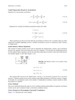
A sling-type psychrometer, as shown in Figure 9.2.1, is an instrument that determines the temperature,
relative humidity, and thus the state of the moist air by measuring its dry bulb and wet bulb temperatures.
It consists of two mercury-in-glass thermometers. The sensing bulb of one of them is dry and is called
the dry bulb. Another sensing bulb is wrapped with a piece of cotton wick, one end of which dips into
a water tube. This wetted sensing bulb is called the wet bulb and the temperature measured by it is
called the wet bulb temperature T′.
When unsaturated moist air flows over the surface of the wetted cotton wick, liquid water evaporates
from its surface. As it absorbs sensible heat, mainly from the surrounding air, the wet bulb temperature
drops. The difference between the dry and wet bulb temperatures is called wet bulb depression (T – T′).
Turning the handle forces the surrounding air to flow over the dry and wet bulbs at an air velocity
between 300 to 600 fpm. Distilled water must be used to wet the cotton wick.
At steady state, if heat conduction along the thermometer stems is neglected and the temperature of
the wetted cotton wick is equal to the wet bulb temperature of the moist air, as the sensible heat transfer
from the surrounding moist air to the cotton wick exactly equals the latent heat required for evaporation,
the heat and mass transfer per unit area of the wet bulb surface can be evaluated as:
(9.2.14)
where h
c
, h
r
=mean conductive and radiative heat transfer coefficient, Btu/hr ft
2
°F
h
d
=mean convective mass transfer coefficient, lb/hr ft
2
FIGURE 9.2.1A sling psychrometer.
Wet bulb
Water tube
Cotton
wick
Dry bulb
Moist air
T
1
, w
1
, h
1
, p
Spindle
Handle
hTT hTThww
crrads
−
′
()
+−
()
=
′
−
()
1
Air-Conditioning and Refrigeration 9-15
© 1999 by CRC Press LLC
T=temperature of undisturbed moist air at a distance from the wet bulb, °F
T
ra
=mean radiant temperature (covered later), °F
w
1
, =humidity ratio of the moist air and the saturated film at the interface of cotton wick and
surrounding air, lb/lb
=latent heat of vaporization at the wet bulb temperature, Btu/lb
The humidity ratio of the moist air is given by:
(9.2.15)
where K′=wet bulb constant, which for a sling psychrometer = 0.00218 1/°F
Le=Lewis number
The wet bulb temperature T′ depends not only on its initial state but also on the rate of heat and mass
transfer at the wet bulb. Therefore, the thermodynamic wet bulb temperature is used in ASHRAE
psychrometric charts.
According to Threlkeld (1970), for a sling psychrometer whose wet bulb diameter is 1 in. and for air
flowing at a velocity of 400 fpm over the wet bulb, if the dry bulb temperature is 90°F and the measured
wet bulb temperature is 70°F, the difference between the measured wet bulb and the thermodynamic
wet bulb (T′ – T
*
)/(T
*
– T′) is less than 1%.
Psychrometric Charts
A psychrometric chart is a graphical presentation of the thermodynamic properties of moist air and
various air-conditioning processes and air-conditioning cycles. A psychrometric chart also helps in
calculating and analyzing the work and energy transfer of various air-conditioning processes and cycles.
Psychrometric charts currently use two kinds of basic coordinates:
1.h-w charts. In h-w charts, enthalpy h, representing energy, and humidity ratio w, representing
mass, are the basic coordinates. Psychrometric charts published by ASHRAE and the Charted
Institution of Building Services Engineering (CIBSE) are h-w charts.
2.T-w charts. In T-w charts, temperature T and humidity ratio w are basic coordinates. Psychrometric
charts published by Carrier Corporation, the Trane Company, etc. are T-w charts.
Figure 9.2.2 shows an abridged ASHRAE psychrometric chart. In the ASHRAE chart:
•A normal temperature chart has a temperature range of 32 to 120°F, a high-temperature chart 60
to 250°F, and a low-temperature chart –40 to 50°F. Since enthalpy is the basic coordinate,
temperature lines are not parallel to each other. Only the 120°F line is truly vertical.
•Thermodynamic properties of moist air are affected by atmospheric pressure. The standard
atmospheric pressure is 29.92 in. Hg at sea level. ASHRAE also published charts for high altitudes
of 5000 ft, 24.89 in. Hg, and 7500 ft, 22.65 in. Hg. Both of them are in the normal temperature
range.
•Enthalpy h-lines incline downward to the right-hand side (negative slope) at an angle of 23.5° to
the horizontal line and have a range of 12 to 54 Btu/lb.
•Humidity ratio w-lines are horizontal lines. They range from 0 to 0.28 lb/lb.
•Relative humidity ϕ-lines are curves of relative humidity 10%, 20%, 90% and a saturation
curve. A saturation curve is a curve of the locus of state points of saturated moist air, that is, ϕ
= 100%. On a saturation curve, temperature T, thermodynamic wet temperature bulb T
*
, and dew
point temperature T
dew
have the same value.
′
w
s
′
h
fg
wwKTT hTThTT
1
1=
′
−
′
−
′
()
+−
′
()
−
′
()
[]
{}
()
s r ra c
′
=
′
KcL h
pa fg
e
06667.
9-16 Section 9
© 1999 by CRC Press LLC
• Thermodynamic wet bulb T
*
-lines have a negative slope slightly greater than that of the h-lines.
A T
*
-line meets the T-line of the same magnitude on the saturation curve.
• Moist volume v-lines have a far greater negative slope than h-lines and T
*
-lines. The moist volume
ranges from 12.5 to 15 ft
3
/lb.
Moist air has seven independent thermodynamic properties or property groups: h, T, ϕ, T
*
, p
at
, ρ – v,
and w – p
w
– T
dew
. When p
at
is given, any additional two of the independent properties determine the
state of moist air on the psychrometric chart and the remaining properties.
Software using AutoCAD to construct the psychrometric chart and calculate the thermodynamic
properties of moist air is available. It can also be linked to the load calculation and energy programs to
analyze the characteristics of air-conditioning cycles.
Refer to Wang’s Handbook of Air Conditioning and Refrigeration (1993) and ASHRAE Handbook,
Fundamentals (1993) for details of psychrometric charts and psychrometric tables that list thermody-
namic properties of moist air.
Example 9.2.1
An air-conditioned room at sea level has an indoor design temperature of 75°F and a relative humidity
of 50%. Determine the humidity ratio, enthalpy, density, dew point, and thermodynamic wet bulb
temperature of the indoor air at design condition.
Solution
1. Since the air-conditioned room is at sea level, a psychrometric chart of standard atmospheric
pressure of 14.697 psi should be used to find the required properties.
2. Plot the state point of the room air at design condition r on the psychrometric chart. First, find
the room temperature 75°F on the horizontal temperature scale. Draw a line parallel to the 75°F
FIGURE 9.2.2 The abridged ASHRAE psychrometric chart and the determination of properties as in Example 9.2.1.
40
0.024
0.024
0.016
0.012
0.008
0.004
0
w, lb/lb
T, °F
50 60 70 75 80 90 100 105
0.0093
80
70
60
50
40
20
30
40
28.1
T
dew
55
13.67
ft
3
/lb
h, Btu/lb
32
T-line
T*=62.5°F
14.0
13.0
20%
40%
50%
60%80%90%
ϕ-line
h-line
w-line
T*-line
v-line
r
Air-Conditioning and Refrigeration 9-17
© 1999 by CRC Press LLC
temperature line. This line meets the relative humidity curve of 50% at point r, which denotes
the state point of room air as shown in Figure 9.2.2.
3.Draw a horizontal line toward the humidity ratio scale from point r. This line meets the ordinate
and thus determines the room air humidity ratio ϕ
r
= 0.0093 lb/lb.
4.Draw a line from point r parallel to the enthalpy line. This line determines the enthalpy of room
air on the enthalpy scale, h
r
= 28.1 Btu/lb.
5.Draw a line through point r parallel to the moist volume line. The perpendicular scale of this line
indicates v
r
= 13.67 ft
3
/lb.
6.Draw a horizontal line to the left from point r. This line meets the saturation curve and determines
the dew point temperature, T
dew
= 55°F.
7.Draw a line through point r parallel to the thermodynamic wet bulb line. The perpendicular scale
to this line indicates that the thermodynamic wet bulb temperature T
*
= 62.5°F.
9-18 Section 9
© 1999 by CRC Press LLC
9.3Air-Conditioning Processes and Cycles
Air-Conditioning Processes
An air-conditioning process describes the change in thermodynamic properties of moist air between the
initial and final stages of conditioning as well as the corresponding energy and mass transfers between
the moist air and a medium, such as water, refrigerant, absorbent or adsorbent, or moist air itself. The
energy balance and conservation of mass are the two principles used for the analysis and the calculation
of the thermodynamic properties of the moist air.
Generally, for a single air-conditioning process, heat transfer or mass transfer is positive. However,
for calculations that involve several air-conditioning processes, heat supplied to the moist air is taken
as positive and heat rejected is negative.
The sensible heat ratio (SHR) of an air-conditioning process is defined as the ratio of the change in
absolute value of sensible heat to the change in absolute value of total heat, both in Btu/hr:
(9.3.1)
For any air-conditioning process, the sensible heat change
(9.3.2)
where =volume flow rate of supply air, cfm
ρ
s
=density of supply air, lb/ft
3
T
2
, T
1
=moist air temperature at final and initial states of an air-conditioning process, °F
and the mass flow rate of supply air
(9.3.3)
The latent heat change is
(9.3.4)
where w
2
,w
1
= humidity ratio at final and initial states of an air-conditioning process, lb/lb.
In Equation (9.3.4), h
fg58
≈ 1060 Btu/lb represents the latent heat of vaporization or condensation of
water at an estimated temperature of 58°F, where vaporization or condensation occurs in an air-handling
unit or packaged unit. Therefore
(9.3.5)
Space Conditioning, Sensible Cooling, and Sensible Heating Processes
In a space conditioning process, heat and moisture are absorbed by the supply air at state s and then
removed from the conditioned space at the state of space air r during summer, as shown by line sr in
Figure 9.3.1, or heat or moisture is supplied to the space to compensate for the transmission and
infiltration losses through the building envelope as shown by line s′r′. Both processes are aimed at
maintaining a desirable space temperature and relative humidity.
The space cooling load q
rc
, in Btu/hr, can be calculated as:
SHR
sen total sen sen 1
==+
()
qqqqq
q VcTT mcTT
sen
s
spa
a
pa
=−
()
=−
()
60 60
21 21
o
o
ρ
V
o
s
mV
o
o
s
s
s
=ρ
q Vwwh Vww
121 21
60 106060≈−
()
=× −
()
oo
s
s
fg.58
s
s
ρρ
SHR
a
pa
a
pa
a
fg.58
=−
()
−
()
+−
()
mcTT mcTT mwwh
ooo
21 21 21
Air-Conditioning and Refrigeration 9-19
© 1999 by CRC Press LLC
(9.3.6)
whereh
r
, h
s
= enthalpy of space air and supply air, Btu/lb.
The space sensible cooling load q
rs
, in Btu/hr, can be calculated from Equation (9.3.2) and the space
latent load q
rl
, in Btu/hr, from Equation (9.3.1). In Equation (9.3.4), T
2
should be replaced by T
r
and T
1
by T
s
. Also in Equation (9.3.1), w
2
should be replaced by w
r
and w
1
by w
s
. The space heating load q
rh
is always a sensible load, in Btu/hr, and can be calculated as:
(9.3.7)
whereT
s
, T
r
= temperature of supply and space air, °F.
A sensible heating process adds heat to the moist air in order to increase its temperature; its humidity
ratio remains constant, as shown by line 12 in Figure 9.3.1. A sensible heating process occurs when
moist air flows over a heating coil. Heat is transferred from the hot water inside the tubes to the moist
air. The rate of heat transfer from the hot water to the colder moist air is often called the heating coil
load q
rh
, in Btu/hr, and is calculated from Equation (9.3.2).
A sensible cooling process removes heat from the moist air, resulting in a drop of its temperature; its
humidity ratio remains constant, as shown by line 1′2′ in Figure 9.3.1. The sensible cooling process
occurs when moist air flows through a cooling coil containing chilled water at a temperature equal to
or greater than the dew point of the entering moist air. The sensible cooling load can also be calculated
from Equation (9.3.2). T
2
is replaced by T
1
and T
1
by T
2′
.
FIGURE 9.3.1Supply conditioning, sensible heating, and sensible cooling processes.
6040 80 100
0.020
0.016
0.012
0.008
0.004
0
w, lb/lb
T, °F
21
r´
s´
r
s
20%
50%
60%
80%
90%
60
40
1´
2´
Coil
m
a
T
2
h
2
w
2
m
a
T
1
h
1
w
1
Conditioned
space
m
a
T
r
h
r
w
r
m
a
T
s
h
s
w
s
s
r
q
rc
.
.
qmhhVhh
rc
a
rs
s
sr s
=−
()
=−
()
60 60
o
o
ρ
qmhhVhh
rc
a
rs
s
sr s
=−
()
=−
()
60 60
o
o
ρ
q mcTT VcTT
rh
a
pa s r
s
spas r
=−
()
=−
()
60 60
o
o
ρ
9-20 Section 9
© 1999 by CRC Press LLC
Humidifying and Cooling and Dehumidifying Processes
In a humidifying process, water vapor is added to moist air and increases the humidity ratio of the moist
air entering the humidifier if the moist air is not saturated. Large-scale humidification of moist air is
usually performed by steam injection, evaporation from a water spray, atomizing water, a wetted medium,
or submerged heating elements. Some details of their construction and characteristics are covered in a
later section. Dry steam in a steam injection humidifying process is often supplied from the main steam
line to a grid-type humidifier and injected into the moist air directly through small holes at a pressure
slightly above atmospheric, as shown by line 12 in Figure 9.3.2(a) and (b). The humidifying capacity
in lb/min, is given by:
(9.3.8)
where w
hl
,w
he
= humidity ratio of moist air leaving and entering the humidifier, lb/lb. The slight inclination
at the top of line 12 is due to the high temperature of the steam. The increase in temperature of the
moist air due to steam injection can be calculated as:
FIGURE 9.3.2Humidifying and cooling and dehumidifying processes: (a) process on psychrometric chart, (b)
steam humidifier, (c) air washer, and (d) water cooling or DX coil.
80
0.020
0.016
0.012
0.008
0.004
0
w, lb/lb
T, °F
20%
50%
90%
60
40
T
1
h
1
w
1
m
a
T
2
h
2
w
2
m
a
(b)
T
1
h
1
w
1
m
a
T
2
h
2
w
2
m
a
(c)
m
a
T
m
h
m
w
m
.
m
a
T
cc
h
cc
w
cc
.
(d)
70605040 90 100 110 120
14.514.013.513.012.5
T
cc
ad
50
70
m
S HR
c
1´
2
1
2´
3*
0
cc
(a)
m
o
hu
,
mVww
o
o
hu
s
shl he
=−
()
ρ
Air-Conditioning and Refrigeration 9-21
© 1999 by CRC Press LLC
(9.3.9)
whereT
2
, T
1
=temperature of moist air at initial and final states, °F
w
sm
=ratio of mass flow rate of injected steam to moist air,
T
s
=temperature of injected steam, °F
w
12
=average humidity ratio of moist air, lb/lb
An air washer is a device that sprays water into moist air in order to humidify, to cool and dehumidify,
and to clean the air, as shown in Figure 9.3.2(c). When moist air flows through an air washer, the moist
air is humidified and approaches saturation. This actual adiabatic saturation process approximately
follows the thermodynamic wet bulb line on the psychrometric chart as shown by line 1′2′. The humidity
ratio of the moist air is increased while its temperature is reduced. The cooling effect of this adiabatic
saturation process is called evaporative cooling.
Oversaturation occurs when the amount of water present in the moist air w
os
, in lb/lb, exceeds the
saturated humidity ratio at thermodynamic wet bulb temperature as shown in Figure 9.3.2(a). When
moist air leaves the air washer, atomizing humidifier, or centrifugal humidifier after humidification, it
often contains unevaporated water droplets at state point 2′, w
w
, in lb/lb. Because of the fan power heat
gain, duct heat gain, and other heat gains providing the latent heat of vaporization, some evaporation
takes place due to the heat transfer to the water drops, and the humidity ratio increases further. Such
evaporation of oversaturated drops is often a process with an increase of both humidity ratio and enthalpy
of moist air. Oversaturation can be expressed as:
(9.3.10)
where w
2′
=humidity ratio at state point 2′, lb/lb
w
o
=sum of w
2′
and w
w
, lb/lb
The magnitude of w
w
depends mainly on the construction of the humidifier and water eliminator, if any.
For an air washer, w
w
may vary from 0.0002 to 0.001 lb/lb. For a pulverizing fan without an eliminator,
w
w
may be up to 0.00135 lb/lb.
Cooling and Dehumidifying Process
In a cooling and dehumidifying process, both the humidity ratio and temperature of moist air decrease.
Some water vapor is condensed in the form of liquid water, called a condensate. This process is shown
by curve m cc on the psychrometric chart in Figure 9.3.2(a). Here m represents the entering mixture of
outdoor and recirculating air and cc the conditioned air leaving the cooling coil.
Three types of heat exchangers are used in a cooling and dehumidifying process: (1) water cooling
coil as shown in Figure 9.3.2(d); (2) direct expansion DX coil, where refrigerant evaporates directly
inside the coil’s tubes; and (3) air washer, in which chilled water spraying contacts condition air directly.
The temperature of chilled water entering the cooling coil or air washer T
we
, in °F, determines whether
it is a sensible cooling or a cooling and dehumidifying process. If T
we
is smaller than the dew point of
the entering air in the air washer, or T
we
makes the outer surface of the water cooling coil T
s.t
<
it is a cooling and dehumidifying process. If T
we
≥ or T
s.t
≥ sensible cooling occurs. The
cooling coil’s load or the cooling capacity of the air washer q
cc
, in Btu/hr, is
(9.3.11a)
where h
ae
, h
cc
=enthalpy of moist air entering and leaving the coil or washer, Btu/lb
=mass flow rate of the condensate, lb/min
h
w
=enthalpy of the condensate, Btu/lb
TTwcTcwc
21 12
−
()
=+
()
smpss pd ps
mm
oo
s
a
/
w
s
*
,
wwwwww
os o s
*
ws
*
=−=+
()
−
′
2
′′
T
ae
′′
T
ae
,
′′
T
ae
,
′′
T
ae
,
qVhhmh
cc
s
sae cc
w
w
=−
()
−60 60
o
o
ρ
m
o
w
9-22 Section 9
© 1999 by CRC Press LLC
Since the thermal energy of the condensate is small compared with q
cc
, in practical calculations the term
is often neglected, and
(9.3.11b)
The sensible heat ratio of the cooling and dehumidifying process SHR
c
can be calculated from
(9.3.12)
where q
cs
= sensible heat removed during the cooling and dehumidifying process, Btu/hr. SHR
c
is shown
by the slope of the straight line joining points m and cc.
The relative humidity of moist air leaving the water cooling coil or DX coil depends mainly on the
outer surface area of the coil including pipe and fins. For coils with ten or more fins per inch, if the
entering moist air is around 80°F dry bulb and 68°F wet bulb, the relative humidity of air leaving the
coil (off-coil) may be estimated as:
Four-row coil 90 to 95%
Six-row and eight-row coils 96 to 98%
Two-Stream Mixing Process and Bypass Mixing Process
For a two-stream adiabatic mixing process, two moist air streams, 1 and 2, are mixed together adiabat-
ically and a mixture m is formed in a mixing chamber as shown by line 1 m1 2 in Figure 9.3.3. Since
the AHU or PU is well insulated, the heat transfer between the mixing chamber and ambient air is small
and is usually neglected. Based on the principle of heat balance and conservation of mass:
(9.3.13)
In Equation (9.3.13), represents the mass flow rate of air, lb/min; h the enthalpy, in Btu/lb; w the
humidity ratio, in lb/lb; and T the temperature, in °F. Subscripts 1 and 2 indicate air streams 1 and 2
and m the mixture; also,
(9.3.14)
Similarly,
(9.3.15)
Mixing point m must lie on the line that joins points 1 and 2 as shown in Figure 9.3.3.
If the differences between the density of air streams 1 and 2 and the density of the mixture are
neglected,
60mh
o
w
w
qVhh
cc
s
sae cc
=−
()
60
o
ρ
SHR
ccscc
mhmh mh
mwmw mw
mTmTmT
ooo
ooo
ooo
1
1
2m
m
1
1
2m
m
1
1
2m
m
+=
+=
+=
2
2
2
m
o
mmhhhhwwww
oo
1m
m1 m1
line segment m1 2 line segment 12
=−
()
−
()
=−
()
−
()
=
()()
2222
mm hhhh wwww
oo
2m
m1 1 m1 1
line segment 1 m1 line segment 12
=−
()
−
()
=−
()
−
()
=
()()
22
Air-Conditioning and Refrigeration 9-23
© 1999 by CRC Press LLC
(9.3.16)
(9.3.17)
In a bypass mixing process, a conditioned air stream is mixed with a bypass air stream that is not
conditioned. The cold conditioned air is denoted by subscript cc, the heated air ch, and the bypass air by.
Equations (9.3.14) and (9.3.17) can still be used but subscript 1 should be replaced by cc or ch and
subscript 2 by “by” (bypass).
Let K
cc
= and K
ch
= then the cooling coil’s load q
cc
and heating coil’s load q
ch
,
both in Btu/hr, for a bypass mixing process are
FIGURE 9.3.3 Mixing processes.
6040 80 100
0.020
0.016
0.012
0.008
0.004
0
w, lb/lb
T, °F
ch
cc
s
20%
50%
90%
60
40
14.0
Hot
deck
m
2
T
2
h
2
w
2
m1
m2
m2
2
1
m1
13.0
m
m
T
m
h
m
w
m
m
1
, T
1
, h
1
, w
1
Two-stream
adiabatic mixing
m
a
T
m1
h
m1
w
m1
m
a
T
m2
h
m2
w
m2
m
by
(m
ch
)
m
cc
(m
by
)
Cold
deck
Bypass mixing
.
.
.
.
.
Vh Vh V h
Vw Vw V w
VT VT V T
oo o
oo o
oo o
1
1
2m
m
1
1
2m
m
1
1
2m
m
+=
+=
+=
2
2
2
VV V
oo o
12 m
+=
mm
cc
m
oo
/
mm
ch
m
oo
/;
9-24 Section 9
© 1999 by CRC Press LLC
(9.3.18)
In Equation (9.3.18), subscript s denotes the supply air and m the mixture air stream.
Air-Conditioning Cycle and Operating Modes
An air-conditioning cycle comprises several air-conditioning processes that are connected in a sequential
order. An air-conditioning cycle determines the operating performance of the air system in an air-
conditioning system. The working substance to condition air may be chilled or hot water, refrigerant,
desiccant, etc.
Each type of air system has its own air-conditioning cycle. Psychrometric analysis of an air-condi-
tioning cycle is an important tool in determining its operating characteristics and the state of moist air
at various system components, including the volume flow rate of supply air, the coil’s load, and the
humidifying and dehumidifying capacity.
According to the cycle performance, air-conditioning cycles can be grouped into two categories:
• Open cycle, in which the moist air at its end state does not resume its original state. An air-
conditioning cycle with all outdoor air is an open cycle.
• Closed cycle, in which moist air resumes its original state at its end state. An air-conditioning
cycle that conditions the mixture of recirculating and outdoor air, supplies it, recirculates part of
the return air, and mixes it again with outdoor air is a closed cycle.
Based on the outdoor weather and indoor operating conditions, the operating modes of air-conditioning
cycles can be classified as:
• Summer mode: when outdoor and indoor operating parameters are in summer conditions.
• Winter mode: when outdoor and indoor operating parameters are in winter conditions.
• Air economizer mode: when all outdoor air or an amount of outdoor air that exceeds the minimum
amount of outdoor air required for the occupants is taken into the AHU or PU for cooling. The
air economizer mode saves energy use for refrigeration.
Continuous modes operate 24 hr a day and 7 days a week. Examples are systems that serve hospital
wards and refrigerated warehouses. An intermittently operated mode usually shuts down once or several
times within a 24-hr operating cycle. Such systems serve offices, class rooms, retail stores, etc. The 24-
hr day-and-night cycle of an intermittently operated system can again be divided into:
1. Cool-down or warm-up period. When the space is not occupied and the space air temperature is
higher or lower than the predetermined value, the space air should be cooled down or warmed
up before the space is occupied.
2. Conditioning period. The air-conditioning system is operated during the occupied period to
maintain the required indoor environment.
3. Nighttime shut-down period. The air system or terminal is shut down or only partly operating to
maintain a set-back temperature.
Summer, winter, air economizer, and continuously operating modes consist of full-load (design load)
and part-load operations. Part load occurs when the system load is less than the design load. The capacity
of the equipment is selected to meet summer and winter system design loads as well as system loads
in all operating modes.
qKVhh
qKVhh
cc cc
s
sm cc
ch ch
s
s2 1
=−
()
=−
()
o
o
ρ
ρ