Handbook Of Air Conditioning And Refrigeration P2
Bạn đang xem bản rút gọn của tài liệu. Xem và tải ngay bản đầy đủ của tài liệu tại đây (157.94 KB, 10 trang )
2. Variation of the properties of water vapor attributable to the effect of pressure
3. Effect of intermolecular forces on the properties of water vapor itself
For an ideal gas, Z ϭ 1. According to the information published by the former National Bureau
of Standards of the United States, for dry air at standard atmospheric pressure (29.92 in. Hg, or 760
mm Hg) and a temperature of 32 to 100°F (0 to 37.8°C) the maximum deviation is about 0.12
percent. For water vapor in moist air under saturated conditions at a temperature of 32 to 100°F
(0 to 37.8°C), the maximum deviation is about 0.5 percent.
Calculation of the Properties of Moist Air
The most exact calculation of the thermodynamic properties of moist air is based on the formula-
tions developed by Hyland and Wexler of the U.S. National Bureau of Standards. The psychromet-
ric chart and tables of ASHRAE are constructed and calculated from these formulations.
Calculations based on the ideal gas equations are the simplest and can be easily formulated. Ac-
cording to the analysis of Nelson and Pate, at a temperature between 0 and 100°F (Ϫ17.8 and 37.8°C),
calculations of enthalpy and specific volume using ideal gas equations show a maximum deviation of
0.5 percent from the exact calculations by Hyland and Wexler. Therefore, ideal gas equations will be
used in this text for the formulation and calculation of the thermodynamic properties of moist air.
Although air contaminants may seriously affect the health of occupants of the air conditioned
space, they have little effect on the thermodynamic properties of moist air since their mass concen-
tration is low. For simplicity, moist air is always considered as a binary mixture of dry air and water
vapor during the analysis and calculation of its properties.
2.2 DALTON’S LAW AND THE GIBBS-DALTON LAW
Dalton’s law shows that for a mixture of gases occupying a given volume at a certain temperature,
the total pressure of the mixture is equal to the sum of the partial pressures of the constituents of the
mixture, i.e.,
p
m
ϭ p
1
ϩ p
2
ϩиии (2.5)
where p
m
ϭ total pressure of mixture, psia (Pa)
p
1
, p
2
,...ϭ partial pressure of constituents 1, 2,...,psia (Pa)
The partial pressure exerted by each constituent in the mixture is independent of the existence of
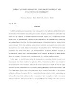
other gases in the mixture. Figure 2.1 shows the variation of mass and pressure of dry air and water
vapor, at an atmospheric pressure of 14.697 psia (101,325 Pa) and a temperature of 75°F (23.9°C).
The principle of conservation of mass for nonnuclear processes gives the following relationship:
m
m
ϭ m
a
ϩ m
w
(2.6)
where m
m
ϭ mass of moist air, lb (kg)
m
a
ϭ mass of dry air, lb (kg)
m
w
ϭ mass of water vapor, lb (kg)
Applying Dalton’s law for moist air, we have
p
at
ϭ p
a
ϩ p
w
(2.7)
where p
at
ϭ atmospheric pressure or pressure of the outdoor moist air, psia (Pa)
p
a
ϭ partial pressure of dry air, psia (Pa)
p
w
ϭ partial pressure of water vapor, psia (Pa)
PSYCHROMETRICS
2.3
Dalton’s law is based on experimental results. It is more accurate for gases at low pressures.
Dalton’s law can be further extended to state the relationship of the internal energy, enthalpy, and
entropy of the gases in a mixture as the Gibbs-Dalton law:
m
m
u
m
ϭ m
1
u
1
ϩ m
2
u
2
ϩиии
m
m
h
m
ϭ m
1
h
1
ϩ m
2
h
2
ϩиии (2.8)
m
m
s
m
ϭ m
1
s
1
ϩ m
2
s
2
ϩиии
where m
m
ϭ mass of gaseous mixture, lb (kg)
m
1
, m
2
,...ϭ mass of the constituents, lb (kg)
u
m
ϭ specific internal energy of gaseous mixture, Btu /lb (kJ/kg)
u
1
, u
2
,...ϭ specific internal energy of constituents, Btu /lb (kJ /kg)
h
m
ϭ specific enthalpy of gaseous mixture, Btu/lb (kJ /kg)
h
1
, h
2
,...ϭ specific enthalpy of constituents, Btu/lb (kJ /kg)
s
m
ϭ specific entropy of gaseous mixture, Btu/lb и °R (kJ /kg иK)
s
1
, s
2
,...ϭ specific entropy of constituents, Btu/lb и °R (kJ /kg иK)
2.3 AIR TEMPERATURE
Temperature and Temperature Scales
The temperature of a substance is a measure of how hot or cold it is. Two systems are said to have
equal temperatures only if there is no change in any of their observable thermal characteristics
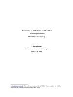
when they are brought into contact with each other. Various temperature scales commonly used to
measure the temperature of various substances are illustrated in Fig. 2.2.
In conventional inch-pound (I-P) units, at a standard atmospheric pressure of 14.697 psia
(101,325 Pa), the Fahrenheit scale has a freezing point of 32°F (0°C) at the ice point, and a boiling
point of 212°F (100°C). For the triple point with a pressure of 0.08864 psia (611.2 Pa), the magni-
tude on the Fahrenheit scale is 32.018°F (0.01°C). There are 180 divisions, or degrees, between the
boiling and freezing points in the Fahrenheit scale. In the International System of Units (SI units),
the Celsius or Centigrade scale has a freezing point of 0°C and a boiling point of 100°C. There are
2.4
CHAPTER TWO
FIGURE 2.1 Mass and pressure of dry air, water vapor, and moist air.
100 divisions between these points. The triple point is at 0.01°C. The conversion from Celsius scale
to Fahrenheit scale is as follows:
°F ϭ 1.8(°C) ϩ 32 (2.9)
For an ideal gas, at T
R
ϭ 0, the gas would have a vanishing specific volume. Actually, a real gas
has a negligible molecular volume when T
R
approaches absolute zero. A temperature scale that in-
cludes absolute zero is called an absolute temperature scale. The Kelvin absolute scale has the same
boiling-freezing point division as the Celsius scale. At the freezing point, the Kelvin scale is 273.15 K.
Absolute zero on the Celsius scale is Ϫ273.15°C. The Rankine absolute scale division is equal to
that of the Fahrenheit scale. The freezing point is 491.67°R. Similarly, absolute zero is Ϫ459.67°F
on the Fahrenheit scale.
Conversions between Rankine and Fahrenheit and between Kelvin and Celsius systems are
R ϭ 459.67 ϩ °F (2.10)
K ϭ 273.15 ϩ °C (2.11)
Thermodynamic Temperature Scale
On the basis of the second law of thermodynamics, one can establish a temperature scale that is
independent of the working substance and that provides an absolute zero of temperature; this is
called a thermodynamic temperature scale. The thermodynamic temperature T must satisfy the
following relationship:
(2.12)
where Q ϭ heat absorbed by reversible engine, Btu /h (kW)
Q
o
ϭ heat rejected by reversible engine, Btu/h (kW)
T
R
ϭ temperature of heat source of reversible engine, °R (K)
T
Ro
ϭ temperature of heat sink of reversible engine, °R (K)
Two of the ASHRAE basic tables, “Thermodynamic Properties of Moist Air ” and “Thermody-
namic Properties of Water at Saturation,” in ASHRAE Handbook 1993, Fundamentals, are based on
the thermodynamic temperature scale.
T
R
T
Ro
ϭ
Q
Q
o
PSYCHROMETRICS
2.5
FIGURE 2.2 Commonly used temperature scales.
Temperature Measurements
During the measurement of air temperatures, it is important to recognize the meaning of the terms
accuracy, precision,and sensitivity.
1. Accuracy is the ability of an instrument to indicate or to record the true value of the measured
quantity. The error indicates the degree of accuracy.
2. Precision is the ability of an instrument to give the same reading repeatedly under the same con-
ditions.
3. Sensitivity is the ability of an instrument to indicate change of the measured quantity.
Liquid-in-glass instruments, such as mercury or alcohol thermometers, were commonly used in
the early days for air temperature measurements. In recent years, many liquid-in-glass thermome-
ters have been replaced by remote temperature monitoring and indication systems, made possible
by sophisticated control systems. A typical air temperature indication system includes sensors, am-
plifiers, and an indicator.
Sensors. Air temperature sensors needing higher accuracy are usually made from resistance tem-
perature detectors (RTDs) made of platinum, palladium, nickel, or copper wires. The electrical
resistance of these resistance thermometers characteristically increases when the sensed ambient
air temperature is raised; i.e., they have a positive temperature coefficient
␣
. In many engineering
applications, the relationship between the resistance and temperature can be given by
(2.13)
where R ϭ electric resistance, ⍀
R
32
, R
212
ϭ electric resistance, at 32 and 212°F (0 and 100°C), respectively, ⍀
T ϭ temperature, °F (°C)
The mean temperature coefficient
␣
for several types of metal wires often used as RTDs is shown
below:
Many air temperature sensors are made from thermistors of sintered metallic oxides, i.e.,
semiconductors. They are available in a large variety of types: beads, disks, washers, rods, etc. Ther-
mistors have a negative temperature coefficient. Their resistance decreases when the sensed air tem-
perature increases. The resistance of a thermistor may drop from approximately 3800 to 3250 ⍀ when
the sensed air temperature increases from 68 to 77°F (20 to 25°C). Recently developed high-quality
thermistors are accurate, stable, and reliable. Within their operating range, commercially available
thermistors will match a resistance-temperature curve within approximately 0.1°F (0.056°C). Some
manufacturers of thermistors can supply them with a stability of 0.05°F (0.028°C) per year. For direct
digital control (DDC) systems, the same sensor is used for both temperature indication, or monitor-
ing, and temperature control. In DDC systems, RTDs with positive temperature coefficient are
widely used.
Measuring range,°F
␣
, ⍀/ °F
Platinum Ϫ400 to 1350 0.00218
Palladium 400 to 1100 0.00209
Nickel Ϫ150 to 570 0.0038
Copper Ϫ150 to 400 0.0038
␣
Ϸ
R
212
Ϫ R
32
180 R
32
R Ϸ R
32
(1 ϩ
␣
T )
2.6
CHAPTER TWO
Amplifier(s). The measured electric signal from the temperature sensor is amplified at the solid
state amplifier to produce an output for indication. The number of amplifiers is matched with the
number of the sensors used in the temperature indication system.
Indicator. An analog-type indicator, one based on directly measurable quantities, is usually a
moving coil instrument. For a digital-type indicator, the signal from the amplifier is compared with
an internal reference voltage and converted for indication through an analog-digital transducer.
2.4 HUMIDITY
Humidity Ratio
The humidity ratio of moist air w is the ratio of the mass of water vapor m
w
to the mass of dry air m
a
contained in the mixture of the moist air, in lb /lb (kg/kg). The humidity ratio can be calculated as
(2.14)
Since dry air and water vapor can occupy the same volume at the same temperature, we can apply the
ideal gas equation and Dalton’s law for dry air and water vapor. Equation (2.14) can be rewritten as
(2.15)
where R
a
, R
w
ϭ gas constant for dry air and water vapor, respectively, ftиlb
f
/lb
m
и°R(J/ kgиK). Equa-
tion (2.15) is expressed in the form of the ratio of pressures; therefore, p
w
and p
at
must have the
same units, either psia or psf (Pa).
For moist air at saturation, Eq. (2.15) becomes
(2.16)
where p
ws
ϭ pressure of water vapor of moist air at saturation, psia or psf (Pa).
Relative Humidity
The relative humidity
of moist air, or RH, is defined as the ratio of the mole fraction of water va-
por x
w
in a moist air sample to the mole fraction of the water vapor in a saturated moist air sample
x
ws
at the same temperature and pressure. This relationship can be expressed as
(2.17)
And, by definition, the following expressions may be written:
(2.18)
(2.19) x
ws
ϭ
n
ws
n
a
ϩ n
ws
x
w
ϭ
n
w
n
a
ϩ n
w
ϭ
x
w
x
ws
͉
T,p
w
s
ϭ 0.62198
p
ws
p
at
Ϫ p
ws
ϭ
53.352
85.778
p
w
p
at
Ϫ p
w
ϭ 0.62198
p
w
p
at
Ϫ p
w
w ϭ
m
w
m
a
ϭ
p
w
VR
a
T
R
P
a
VR
w
T
R
ϭ
R
a
R
w
p
w
p
at
Ϫ p
w
w ϭ
m
w
m
a
PSYCHROMETRICS
2.7