Surface densified camshaft gear for high performance combustion engines ppt
Bạn đang xem bản rút gọn của tài liệu. Xem và tải ngay bản đầy đủ của tài liệu tại đây (216.36 KB, 5 trang )
Surface densified camshaft gear for high performance combustion engines
1. Background of the Development
The shape of gears is very attractive to the PM manufacturing process. Spur gears
as well as helical gears can be shaped by compaction. The performance of gears is
influenced beneath the geometrical design mainly by the material parameters tooth
root strength σ
FE
and pitting resistance σ
Hlim
. The comparison of these values from
PM gears to wrought steel gears shows clearly, that PM gears can only be used in
low loaded applications (Fig. 1).
Dynamic Material properties
(acc. DIN 3990)
0
200
400
600
800
1000
1200
1400
1600
Steel 16MnCr5 ESint Fe+1,5%Cu+0,4%C
Sress [MPa]
Tooth root strength sFE Pitting resistance sHlim
Fig. 1. Tooth root strength and pitting resistance /1/
The main influence to the differences in mechanical properties has the residual
porosity, which is caused by the PM manufacturing process. The porosity is
distributed in the whole volume of the part. But the stress analysis of torque loaded
gears shows, that the hot spots always appear near the surface of the tooth (Fig. 2).
This leads to the approach to reduce the porosity in the area near the surface.
Effective stress levels [Mpa]
l
ow high
Fig.2: Stress distribution of torque loaded gears
In extensive investigations it was able to show, that the surface-near areas of PM
gears can be densified by a rolling process after sintering (Fig. 3).
Fig. 3: Rolling process and cross section of a rolled PM tooth
The influence of the densified surface layer to the performance of the gear was
investigated at the FZG in Munich. The results are added in the following diagram
(Fig. 4).
Dynamic properties (acc. DIN 3990)
0
200
400
600
800
1000
1200
1400
1600
Steel 16MnCr5 ESint
Fe+1,5%Cu+0,4%C
Sint DENSGRAD
Stress [MPa]
Tooth root strength sFE Pitting resistance sHlim
Fig. 4. Tooth root strength and pitting resistance including DENSGRAD
TM
values.
Based on this extraordinary improvement, the PM DENSGRAD
TM
technology is
in the position to substitute wrought steel gears keeping the existing space.
2. Gear Design by DENSGRAD
TM
technology
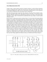
In the course of technical modification of an existing diesel engine (Fig. 5) we were
asked if the two steel gears, which are running the cam shafts can be substituted by
sintered gears. The necessary performance data were well known. A geometrical
change of the gears was due to the already existing engine not possible.
Fig. 5. Diesel Engine with camshaft to camshaft gears
By the use of the Standard Gear Calculation DIN 3990 and based on the determined
material data of the DENDGRAD
TM
process it was possible to show, that
DENSGRAD
TM
gears can fulfil the requirements with sufficient safety factors. This
fact and also economical advantages convinced the customer to test these gears
(Fig. 6). All tests were passed without any failure.
Fig. 6: Cam shaft gears made by the DENSGRAD
TM
technology
3. Manufacturing of DENSGRAD
TM
gears
High performance gears require beneath good mechanical properties especially high
precision tolerances. In order to keep gear class 7 (acc. DIN 3960) we decided to
finish the toothing by a honing operation. This honing process works economically up
to a machining allowance of 0.04 mm. That means that the sum of all tolerances of
the different manufacturing steps has to be within the honing allowance.
The manufacturing steps are:
• Compacting
• Sintering
• Sizing
• Rolling
• Casehardening
• Hard turning
• Honing
• Shipping
Therefore it was necessary to focus on two tasks for the development of rolling
process: a proper densified layer and a near net shape toothing.
The dimensional precision after rolling is mainly effected by the properties of the
sintered material like density distribution and elastic behaviour. The circumferential
density distribution e.g. is directly linked to run out deviations.
The spring back effect after elastic deformation causes also geometrical deviations.
The elastic deflection of the whole part under rolling force is mainly influenced by the
design of the gear. Due to the conical web of the regarding gear it was necessary to
support the gear with a specific clamping device during rolling.
Deviations of tooth profile are mainly caused by elastic deflection during rolling
contact. To compensate these deformations it is necessary to modify the tooth profile
of the rolling tool. To do this in an efficient way, the software GEARCONTUR was
developed (Fig. 7).
Fig. 7: Computer aided rolling tool design – GEARCONTOUR.
4. Experience and response since serial launch
Due to a perfect working project team it was possible to introduce this new
technology into our existing production without big troubles. Up to now approx.
700.000 parts have been produced and delivered without complaints. Beyond that
our customer noticed a clearly reduced meshing noise emission.
The successful market launch of the DENSGRAD
TM
process opens a new and huge
field for high loaded PM gear applications in the future.
Literature:
/1/ Niemann G., Winter H.: Maschinenelemente Band II, Springer Verlag 1989
Appendix: Main dimensions