Surface Chemistry ppt
Bạn đang xem bản rút gọn của tài liệu. Xem và tải ngay bản đầy đủ của tài liệu tại đây (28.2 MB, 210 trang )
Section 3
Surface Chemistry
Chapter 8
Small Molecules and Peptides Inside Carbon
Nanotubes: Impact of Nanoscale Confinement
Peng Xiu , Zhen Xia and Ruhong Zhou
Additional information is available at the end of the chapter
/>1. Introduction
Carbon-based nanoparticles and nanostructures, such as carbon nanotubes (CNTs), have
drawn great attention in both academia and industry due to their wide potential applica‐
tions. Owing to their well-defined one-dimensional (1D) interior, CNTs serve as desirable
materials for encapsulating molecules, such as water [1-4], ionic liquid [5], drug molecules
[6], and biomolecules [7]. The nanoscale confinement of CNTs have considerable impact on
the inner molecules, including changes in their structure, size distribution, surface area, and
dynamics, thus leading to many interesting and striking properties that are quite different
from those in bulk [1-5, 7-9]. For example, nanoscale confinement of CNTs can give rise to
ordered structure and extra-fast motion of water molecules [1-4], significantly enhanced ac‐
tivity of catalytic particles [8], phase transition of ionic liquids from liquid to high-melting-
point crystal [5], and denatured structures of peptide helices [9]. In particular, recent studies
[10-13] have shown that these CNT-based nanomaterials can be used as a new paradigm of
diagnostic and therapeutic tools, which is beyond the traditional organic chemistry based
therapeutics in the current pharmacology. Before their wide applications in the biomedical
filed, the effects of CNTs on biomolecules (and drug molecules) need to be understood thor‐
oughly [14-20].
In this book chapter, we review some of our recent works [21-24], with large scale molecular
dynamics (MD) simulations using massively parallel supercomputers such as IBM Blue
Gene, on the nanoscale confinement of both small molecules and peptides inside the CNT,
which demonstrate wide implications in nanoscale signal processing, single-file transporta‐
tion, drug delivery, and even cytotoxicity. The structure of this chapter will be organized as
following. First, we show that water molecules confined within a Y-shaped CNT can realize
the molecular signal conversion and multiplication, due to the surprisingly strong dipole-
© 2013 Xiu et al.; licensee InTech. This is an open access article distributed under the terms of the Creative
Commons Attribution License ( which permits unrestricted use,
distribution, and reproduction in any medium, provided the original work is properly cited.
induced orientation ordering of confined water wires [25]. Second, we find a striking phe‐
nomen that urea can induce the drying of CNTs and result in single-file urea wires. The
unique properties of a urea wire as well as its biological and technological implications are
discussed [22, 23]. Third, we show that nanoscale confinement can catalyze the chiral transi‐
tion of chiral molecules. We further explore the molecular mechanism of CNT-catalyzed
enantiomerization and provide some implications for drug delivery [24]. Last, we investi‐
gate the effect of confinement of CNT on three important secondary structural motifs of pro‐
teins – a hairpin turn, a helix, and a beta-sheet.
2. Results
2.1. Water-mediated signal multiplication with Y-shaped nanotubes
Uunderstanding the molecular-scale signal transmission (amplification, shunting, etc) has
attracted intensive attentions in recent years because it is of particular importance in many
physical, chemical, and biological applications, such as molecular switches, nano-gates, and
biosensors [26-29]. However, due to the intrinsic complexity of these nano-systems and the
significant noises coming from thermal fluctuations as well as interferences between branch
signals, the molecular details are far from well understood. On the other hand, water mole‐
cules confined within nanochannels exhibit structures and dynamics quite different from
bulk [3], which might provide a medium for molecular signal transmission. Water molecules
inside CNT with a suitable diameter can form a single-file hydrogen-bonded molecular
wire, with the concerted water dipole orientations, i.e., either parallel or antiparallel to the
CNT axis [1, 30, 31]. The characteristic time for reorientation of the dipole orientation of wa‐
ter wire is in the range of 2–3 ns for CNT with a length of 1.34 nm [1], and the water wire
inside a nanochannel can remain dipole-orientation-ordered up to macroscopic lengths of ~
0.1 mm, with durations up to ~ 0.1 s [30]. If we can “tune” the orientation of a water mole‐
cule at one end, we might be able to control the orientations of all water molecules in the
molecular wire and even amplify and shunt the orientation signal.
Recently, Y-shaped nanotubes have been successfully fabricated by means of many different
methods [32-34]. These nanotubes have been found to exhibit both electrical switching and
logic behaviour [27, 35]. In the following, we will show that single-file water wires confined
within a Y-shaped single-walled CNT (hereafter referred to it as Y-SWNT, see Fig. 1) can
perform both signal amplification and shunting, ignited by a single electron, because of the
surprisingly strong interactions between water molecules at the Y-junction. We construct Y-
SWNT by jointing three (6, 6) uncapped armchair single-wall CNTs (SWNTs) together sym‐
metrically along three directions neighbouring 120° one another. An external charge, q, is
positioned at the centre of a second carbon ring of the main nanotube (see Fig. 1) to monitor
the dipole orientation of water wire inside the tube. All carbon atoms were fixed and an op‐
posite charge was assigned at the edge of simulated boxes to keep the whole system charge-
neutral. MD simulations were carried out in NVT ensemble (300K, 1atm) with Gromacs 3.3.3
[36]. The TIP3P [37] water model was used.
Physical and Chemical Properties of Carbon Nanotubes
188
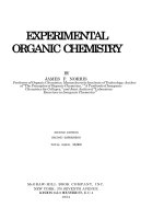
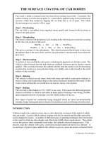
Figure 1. Schematic snapshot of the simulation system in side-view. The Y-SWNT consists of a main tube (MT) and two
branch tubes (BT
1
, BT
2
) positioned in the same plane. Water molecules outside the nanotubes are omitted. The light
blue sphere represents the imposed charge. The water molecule facing the external charge is referred to as “Moni‐
tored-water”. The lengths of MT, BT
1
and BT
2
are 1.44 nm, 1.21 nm, and 1.21 nm, respectively. Insets: Enlarged part for
the typical configurations: upper for q = -e and lower for q = +e. This figure is reproduced from ref. [21] with permis‐
sion.
The simulations show that water molecules in the Y-SWNT form single-file hydrogen-bond‐
ed molecular wires. Although the water wires in different tubes interact at the Y-junction, all
water’s orientations are either parallel or anti-parallel to the nanotube axis, similar as the
case of water wire in conventional SWNT [1]. To describe quantitatively the confined wa‐
ter’s dipole orientation, we choose an angle ϕ
i
between the dipole orientation of ith water
molecule and the SWNT axis, and the average angle
φ
¯
(
t
)
, which the average over all the
water molecules inside a nanotube at some time t. The outward direction of the main tube
and inward directions of the branch tubes are set as positive directions. The results are dis‐
played in Fig. 2(A). It is clear that
φ
¯
dominantly falls in two ranges for each nanotube, 10˚<
φ
¯
<70˚ and 110˚< φ
¯
<170˚, indicating that the water molecules within each nanotube are near‐
ly aligned. Furthermore, we have noticed that φ
¯
(
t
)
for all tubes falls in the range from 10˚ to
70˚ when q = -e, with few fluctuations to larger values. In contrast, when q = +e,
φ
¯
(
t
)
for the
main tube primarily falls into the range from 110˚ to 170˚. For the branch tubes, φ
¯
(
t
)
jumps
between the two ranges. From the water orientations in each branch tube, we can easily
identify the sign of the imposed charge, i.e., the charge signal at the main tube correctly
transmits and is amplified/shunted to the two branch tubes.
To further characterize the molecular signal transmission, we define an integer s(t): s(t) = +1
when 10˚<
φ
¯
<70˚, and s(t) = -1 when 110˚< φ
¯
<170˚. We calculate the P(t), defined as the oc‐
currence probability of s(t) = +1 from the start of the simulation until the time t in each tube.
For a sufficiently long time, P(t) in both branch tubes will approach 1.0 when q=-e, and ap‐
proach 0.5 when q =+e since φ
¯
(
t
)
falls in the two different ranges with an equal probability.
Here, we set P
C
= 0.8 as the threshold value to determine the charge. It is expected that P> P
C
indicates q = -e, and that P< P
C
indicates q = +e. From Fig. 2(B) we can see that, for both
branch tubes, when q = -e, P> P
C
for t> 1 ns; when q = +e, P< P
C
for t> 8 ns. Consequently, the
Small Molecules and Peptides Inside Carbon Nanotubes: Impact of Nanoscale Confinement
/>189
charge signal at the main tube can be readily distinguished from the value of P(t) in each
branch tube within a time interval of ~8 ns.
Figure 2. Trajectory of average dipole angle
φ
¯
(
t
)
of the water orientation and the probability of dipole orientation P(t)
in each tube in a Y-SWNT. (A) Average dipole angle in the main tube (MT), first branch tube (BT
1
) and second branch
tube (BT
2
) for a negative charge (left) and a positive charge (right) in the main tube. (B) P(t) in different tubes for a
negative charge (solid lines) and a positive charge (dashed lines). P(t) for a negative charge converges to about 1.0
within a few nanoseconds. This figure is reproduced from ref. [21] with permission.
Figure 3. Snapshot of a three Y-junction (3Y-SWNT) system (side view). Colours match those in Fig. 1. The angle be‐
tween any two neighbouring tubes at each Y-junction is 120
°
. The lengths of the main tube (MT), two middle tubes
denoted by MT
1
and MT
2
, and four branch tubes denoted by BT
1
, BT
2
, BT
3
and BT
4
are 1.44 nm, 1.44 nm, and 1.21 nm,
respectively. This figure is reproduced from ref. [21] with permission.
Careful examinations reveal that the external charge “monitors” the water molecule facing
this charge (referred to as the “Monitored-water”); the Monitored-water determines the wa‐
ter orientations in the main tube; the uppermost water molecule in the main tube governs
the dipole orientations of the bottommost water molecules in branch tubes and hence the
water dipole orientations within both branch tubes (see ref. [21] for more discussions). In ad‐
dition, we find that the response to the switching of the charge signal is very rapid, from a
few nanoseconds to a few hundred nanoseconds: In response to -e→+e signal switching, the
Physical and Chemical Properties of Carbon Nanotubes
190
time delay for the branch tubes is 40 ns on average with a maximal duration of 150 ns; in
response to +e→-e polarity flip, it is only around 4ns.
Figure 4. Probability P(t) in the main tube (black line), two middle tubes (blue and red solid lines), and four branch
tubes (dashed lines) in response to a negative (A) and a positive (B) imposed charge signal. This figure is reproduced
from ref. [21] with permission.
The charge signal can also be transmitted and amplified/shunted through additional chan‐
nels. We have simulated a system with three Y-junctions where each of the outlet branch
tubes forms a Y-junction connecting two more tubes (see Fig. 3). We refer the two middle
tubes as MT
1
and MT
2
, and the four branch tubes as BT
1
, BT
2
, BT
3
and BT
4
. Fig. 4 shows the
P(t) for different branch tubes. It is found that when t > 200 ns, P(t) > P
C
when q = -e, and
P(t) < P
C
when q = +e, for all branch tubes. As a consequence, the charge signal at the main
tube transmits to four branch tubes with a temporal resolution time of ~200 ns.
To summarize, by using MD simulations we show that a signal at the single-electron level
can be converted and multiplied into two or more signals by water wires confined within a
narrow Y-shaped CNT. This remarkable capability of signal transduction by Y-SWNT de‐
rives from the surprisingly strong dipole-induced ordering of such water wires, so that the
concerted water orientations in the two branches of the Y-SWNT can be modulated by the
orientation of water wire in the main channel. The response to the switching of the charge
signal is found to be very rapid, from a few nanoseconds to a few hundred nanoseconds. To
our knowledge, this is the first observation of the remarkable signal amplification and
shunting with a Y-shaped nanotube at the atomic level and this observation may have sig‐
nificance for future applications in molecular-scale electronic devices. In addition, it is note‐
worthy that there are Y-shaped biological channels [38, 39], therefore, our findings might
also provide useful insight into the molecular signal transmission in biological systems.
2.2. Molecular wire of urea and induced drying in carbon nanotubes
2.2.1. Molecular wire of urea inside narrow carbon nanotube
Molecules confined inside nanoscale space such as narrow nanotubes or membrane proteins
can form one-dimensional (1D) molecular wires, which have attracted intense interest re‐
cently because of their scientific importance and potential applications in nanotechnology [1,
21, 40-56]. Among them, it is of particular interest in determining the structure and dynami‐
Small Molecules and Peptides Inside Carbon Nanotubes: Impact of Nanoscale Confinement
/>191
cal behavior of water wires [1, 21, 40-49] which have been found to exist in narrow nano‐
tubes[1, 21, 40-42, 46-48] and biological channels [43-45]. Water wires have many interesting
properties, such as wavelike density distributions [1, 46], rapid and concerted motions [1, 40,
43], orientation-ordered structures and collective flips [1, 21, 41, 48], and excellent on-off gat‐
ing behaviors [46, 47]. In addition, it has been observed that the methane [56], methanol [54],
and gas molecules (O
2
, H
2
, and CO
2
) [55] preferentially bind to the interiors of narrow
SWNT over water and form 1D molecular wires. Despite the above progress, the properties
of molecular wires have not been fully understood, particularly for the molecular wires
formed by larger polar organic molecules.
Urea plays an important role in the metabolism of nitrogen-containing compounds by ani‐
mals [57, 58], and serves as a common protein chemical denaturant and an important raw ma‐
terial in chemical industry. It is important to note that the biological urea channel dvUT (a urea
transporter from the bacterium Desulfovibrio vulgaris) has a long (~ 16 Å) and narrow selectivi‐
ty filter; this filter consists of closely spaced hydrophobic residues which allows dehydrated
urea to permeate in single-file [58]. The hydrophobic SWNTs with appropriate diameters
might serve as useful model systems for studying biological urea channel. The current simula‐
tions were based on TIP3P water model [37] and two commonly used urea models, namely,
KBFF [59] and OPLS [60, 61] models. Below we mainly present the results for the KBFF case;
the results for OPLS case are similar, and some of them are also shown as comparison. The sim‐
ulation were performed using Gromacs 4.0.7 [62] in an NPT (300K, 1 atm) ensemble.
Figure 5. Number of urea (in blue; KBFF urea model is used) and water (in red) molecules within the 336-carbon (6, 6)
SWNT as a function of simulation time, at 1 M urea concentration. Inset: Snapshot of a “perfect” urea wire.
We have performed MD simulation of 336-carbon (6, 6) SWNT (3.32 nm in length), solvated in
aqueous urea with various urea concentrations (8M, 1 M and 0.5 M, with the simulation
lengths 100 ns, 200 ns, and 200 ns, respectively). Fig. 5 shows the number of solvent (water/
urea) molecules inside the SWNT in case of 1 M urea concentration during the course of simu‐
lation. Almost all water molecules inside the SWNT are replaced by urea within the first 25 ns.
The confined urea molecules form a 1D “perfect” urea wire with a contiguous hydrogen-bond‐
Physical and Chemical Properties of Carbon Nanotubes
192
ed network in most of the simulation time, or occasionally forms a “defective” urea wire [with
a very small number of “water defect(s)”, commonly near the SWNT edge].
Table 1 summarizes the average number of urea ( N
¯
urea
) and water molecules ( N
¯
water
) in‐
side the SWNT after the systems have reached equilibrium with various urea concentra‐
tions. Regardless of urea concentration and urea model used, finally, the SWNTs are nearly
completely filled with urea molecules. Table 1 also shows the occurrence probability for
“perfect” urea wire, P
perfect
, which is high for most cases. These results indicate that urea has
a robust capability to form uninterrupted molecular wire.
Table 1. Average number of urea and water molecules ( f
drying
= R
SWNT
/
R
bulk
and N
¯
urea
, respectively) inside the 336-
carbon (6, 6) SWNT in equilibrium, together with occurrence probabilities for “perfect wire” (P
perfect
a
), with various
urea concentrations (C
urea
) and with different urea models.
Next, we explore the structure of the confined urea wire. We use the case of the 336-carbon
(6, 6) SWNT in 8 M KBFF urea for illustration because P
perfect
in this case is very high (see
Table 1). We performed two independent 100 ns simulations under same conditions, denot‐
ed by case 1 and case 2, respectively. As shown in the inset of Fig. 5, urea molecules inside
(6, 6) SWNT form a single-file structure with a contiguous hydrogen-bonded network and
concerted dipole orientations [urea’s dipole orientation approximates the dipole orientation
of its carbonyl (-CO-) group]. Quantitatively, we have computed ϕ (the angle between a
urea dipole and the nanotube axis). ϕ is found to fall in two ranges: the angle around 20º
(case 1) and around 160º (case 2). No event of flipping between these two ranges is observed
during the time period of 100 ns. Even for urea wire in 144-carbon (6, 6) SWNT, no flipping
event is observed for KBFF urea, and 1~2 flipping events is observed for OPLS urea, during
several independent 100 ns simulations. In contrast, the flipping of water wire inside 144-
carbon (6, 6) SWNT occurs every 2~3 ns on average [1, 48]. Further analysis reveal that the
lower flipping frequency of urea wire compared with water mainly comes from the larger
physical dimension and higher polarity of urea [23].
The above findings have technological implications. Our previous reports [21, 25] have dem‐
onstrated water wires can mediate the signal conversion and multiplication because of their
ordered 1D structure and collective flipping behavior. However, the very small size of the
water and fast flipping of water wire make the experimental realization very difficult [25].
Urea wire has similar ordered 1D structure and flipping behavior as water wire but has a
lower flipping frequency and a high molecular polarity which can facilitate the signal detec‐
tion in practice (urea wire has longer response time [21] to switch its dipole orientation un‐
Small Molecules and Peptides Inside Carbon Nanotubes: Impact of Nanoscale Confinement
/>193
der the influence of a change in charge signal). We therefore expect that urea wire can serve
as a better candidate for signal transduction and multiplication.
Next, we have calculated the position distribution of urea along the nanotube axis. There are
seven distinct, sharp peaks (with an average peak-to-peak value of ~ 4.6 Å), indicating that
the urea wires are translationally ordered along the SWNT axis. The position distribution is
found to be much sharper than water wire owing to the larger molecular size of urea (see
ref. [23] for details).
Figure 6. Potential energy profiles of urea along the axis of 336-carbon (6, 6) SWNT (8 M urea, KBFF urea model is
used). (A) and (B) show the van der Waals (vdW) and electrostatic potentials, respectively. Case 1 and case 2 denote
independent simulation under same conditions. The positions of SWNT inlet/outlet are indicated with dashed lines.
We have also calculated the interaction energies with the rest of the system for a urea mole‐
cule with respect to its axial distance from the geometrical center of SWNT (see Fig. 6). Inter‐
estingly, the vdW potential curves are approximately symmetric; whereas electrostatic
potential curves are observably asymmetric, i.e., correlate to the inner urea’s dipole orienta‐
tions. Urea’s asymmetric molecular partial charge distribution together with the extremely
confined space result in the orientationally ordered structure (concerted dipole orientations)
of molecular wire, thus breaking the symmetry of the system within a finite time period
(more than 100 ns for the present case) and causing an asymmetric electrostatic potential.
Although single-file transport of water through SWNT has been intensively investigated in re‐
cent years [1, 40, 46-48], much less is known about the single-file transportation for organic
small molecules. Here we explore the transport properties of urea wire and make a compari‐
son with water wire. We have calculated the urea flow, defined as the total number of urea
molecules per nanosecond that have entered from one end and leave the SWNT from the op‐
posite side. Given that the biological urea channel dvUT [52] has a length of ~ 16 Å (the num‐
ber of urea molecules accommodated in the selectivity filter is about 3), we chose the 144-
carbon (6, 6) SWNT (13.5 Å in length) as the nanochannel, wherein the resulting urea wire also
consists of ~ 3 urea molecules. To facilitate a direct comparison with water wire, we per‐
formed additional simulations for the SWNT immersed in pure water. The calculated average
flows (averaged over three independent 100 ns simulations) are 0.73 ns
-1
and 0.79 ns
-1
, for KBFF
and OPLS urea, respectively, and it is 16.2 ns
-1
for water. Transportation of urea seems to be 20+
times slower than water. Fig. 7(A) displays the time evolution of urea flow from a typical sim‐
ulation trajectory. The urea flow is low, with a maximal value of only 4 ns
-1
; it vanishes fre‐
Physical and Chemical Properties of Carbon Nanotubes
194
quently, and the duration time of zero value can be up to 6 ns (e.g., t = 11 ns ~ 17 ns). In contrast,
for water wire, its minimal flow is up to 7 ns
-1
, and its maximal flow reaches a value of 32 ns
-1
.
Furthermore, we have studied the influence of urea concentrations (1 M ≤ C
urea
≤ 10 M) of the
surrounding bath on urea’s permeability through SWNT and find a maximal urea flow (~0.87
ns
-1
) around a concentration of 5 M (see ref. [23] for more details).
Figure 7. Single-file transport of urea through 144-carbon (6, 6) SWNT (8 M urea, using KBFF urea for demonstration)
and the underlying physics. (A) Urea flow versus time from a typical trajectory. (B) The potential energy profiles along
the SWNT axis for the urea wire (blue) and the water wire (red), respectively. The data for water derives from the con‐
trol runs of SWNT immersed in pure water.
To understand the physical mechanism behind the enormously lower permeability of urea
relative to water for SWNT, we have calculated the interaction energies of a inner urea/
water molecule with the SWNT (the data for water derives from the control runs of SWNT
immersed in pure water). Because the carbon atoms of SWNT are modeled as uncharged
Lennard-Jones particles, there are only vdW interactions between urea/water and SWNT. As
displayed in Fig 7(B), the potential valley for urea is much deeper than that for water, be‐
cause urea has a stronger dispersion interaction with SWNT than water, which in turn leads
to a much lower permeability of urea than water.
In this section, we have investigated the structure and dynamical behavior of urea wire in‐
side the narrow SWNT. Even at relatively low urea concentration (e.g., 0.5 M), we have ob‐
served spontaneous and continuous filling of SWNT with a 1D urea wire. The resulting urea
wire is translationally and orientationally ordered, with a contiguous hydrogen-bonded net‐
work and concerted dipole orientations of urea molecules. Despite the symmetric nature of
SWNT, the urea’s potential energy profile along SWNT is asymmetric, coming from asym‐
metric molecular partial charge distribution (or dipole moment) and the ordering of urea’s
dipole orientation under extremely confinement. Furthermore, we have studied the single-
file transportation of confined urea, and find that urea flow decreases significantly (by a fac‐
tor of ~ 20) compared to that of water, due to the fact that urea has a stronger dispersion
interaction with SWNT than water. We also find a maximum in urea permeation around a
concentration of 5 M. The studies on the urea wire confined inside SWNT not only help our
understanding of the unique properties of confined polar organic molecules, but also
present biological (biological urea channel) and technological (e.g., electronic devices for sig‐
nal transduction and multiplication at nanoscale) implications.
Small Molecules and Peptides Inside Carbon Nanotubes: Impact of Nanoscale Confinement
/>195
2.2.2. Urea-induced drying of carbon nanotubes
In the previous section, we have demonstrated that urea can expel water inside a narrow
SWNT [(6, 6) SWNT]. One may wonder if this phenomenon can persist in wider SWNT. To
answer this, we performed MD simulations of (17, 8) SWNT (1.73 nm in diameter, it can ac‐
commodate several layers of urea and water) immersed in 8 M urea solution. Considering
that there are some urea models commonly used in literature whose charge distributions are
quite different [22], herein we have used five different urea models to test if the drying phe‐
nomenon is sensitive to force fields used.
The five urea models used in the current study are the OPLS [60, 61], KBFF [59], CHARMM
(parameters derived from the CHARMM22 force field [63]), AMBER
*
[64], and AMBER [pa‐
rameters derived from the file embedded in the AMBER 10 simulation package (University
of California at San Francisco)] urea models. The simulation were performed using Gromacs
4.0.7 [62] in an NPT (300K, 1 atm) ensemble with the simulation lengths of 100 ns for all sys‐
tems. In all cases, we observe that most of water molecules initially inside the SWNT (C
urea
inside the SWNT is approximately 8 M from the initial solvation setup) are repelled from the
SWNT within the first 10 ns; after that, the hydrophobic nanopores are dominantly occupied
by urea. Table 2 lists the average number of urea and water molecules inside (17, 8) SWNT
with different urea models. To quantitatively characterize the drying effect, we have calcu‐
lated the “drying factor”, f
drying
, defined as following:
drying SWNT bulk
/f R R=
(1)
where R
SWNT
and R
bulk
are the ratios of the average number of urea to water molecules in‐
side SWNT and in the bulk region, respectively. A larger f
drying
means a stronger urea-in‐
duced drying effect. f
drying
for different urea models are also shown in Table 2. In all cases, f
drying
is very high, indicating that strong drying phenomena occur in all cases.
Table 2. Average number of urea (
N
¯
urea
) and water molecules (
N
¯
water
) inside (17, 8) SWNT together with the drying
factors, f
drying
(see text for the definition) with different urea models. These data were averaged over the time region
wherein the systems have reached equilibrium (t ≥ 90 ns).
Physical and Chemical Properties of Carbon Nanotubes
196
To understand the observed phenomenon of urea-induced drying of SWNTs, we have calcu‐
lated the difference in average interaction energies for a solvent (urea/water) in bulk and in
(17, 8) SWNT with the rest of the system. As the solvent molecules move from bulk into the
(17, 8) SWNT, both urea and water lose electrostatic interaction energies, but urea gains
more vdW energy than water (about 3~4 times larger than water), which mainly comes from
the stronger dispersion interaction of urea than water with nanotube. As a consequence, af‐
ter a solvent penetrates the SWNT, on average each urea gains 2.55~4.58 kcal/mol whereas
each water loses 0.12~1.64 kcal/mol. It is noteworthy that the replacement of structurally
confined water by larger urea (on average each urea molecule can replace ~2.5 water mole‐
cules) is also favorable in overall free energy due to an overall solvent entropy gain. In addi‐
tion, the free energy analysis [by calculating the potential of mean force (PMF)] also support
that the phenomenon of urea-induced drying of SWNT derives from the stronger dispersion
interaction of urea with SWNT than water (see ref. [22] for details).
In conclusion, by using MD simulation we have observed a striking phenomenon of urea-
induced drying of hydrophobic nanotubes and demonstrated the robustness of this phe‐
nomenon by using five different urea models. By decomposing the interaction energies for a
solvent molecule into electrostatic and vdW components, we find that the drying phenom‐
enon results from the stronger dispersion interaction of urea than water with nanotube.
These results also have implications on understanding the urea-induced denaturation of
proteins by providing further evidence of the potential existence of a “dry globule”-like
transient state [65] during early stage of protein unfolding and the “direct interaction mech‐
anism” whereby urea attacks protein directly via favorable dispersion interaction, rather
than disrupts water structure as a “water breaker”. In addition, this study points out the
crucial role of dispersion interaction in the selective absorption of molecules inside hydro‐
phobic nanopores [54-56], which might be important for nanoscience and nanotechnology.
2.3. Chirality switch of drug-like molecules inside boron-nitride nanotubes
Many basic building materials of organism, such as amino acids and saccharides, are chiral
in nature. Understanding the molecular chirality is very important for pharmaceutical prod‐
ucts because the biological systems have stereoselectivity [66]. Some molecules chiral stable
in bulk systems may undergo conformational transitions in human body [67]. For example,
in late 1950s and early 1960s, thalidomide caused serious damages to the fetal growth,
known as the “thalidomide tragedy” [67, 68], which correlates to a chiral transition of thali‐
domide occurred in human body. Hence, good conformational stability is an important re‐
quirement for chiral molecules used in pharmaceutical products and drug delivery.
It is well-known that there are various nanoscale confinement environments in human
body, but the effect of nano-confinement on molecular chirality is still poorly understood so
far. Here we use MD simulations (employing Gromacs 3.3.1 [36]) to study the chiral transi‐
tion of difluorobenzo[c]phenanthrene molecules (C
18
H
12
F
2
, referred to as “D molecule”) in
single-walled boron-nitride nanotubes (SWBNNTs). Molecular systems can be chiral by
asymmetrically arranging atoms in space around a center, axis, or plane, which are called
point, axial, and planar chirality, respectively [69]. It has been reported using infrared laser
Small Molecules and Peptides Inside Carbon Nanotubes: Impact of Nanoscale Confinement
/>197
pulses that D molecule show the planar chirality transition between P-enantiomer and M-
enantiomer, and the energy barrier for this transition in bulk was estimated to be only
6.7-8.0 kcal/mol [70]. The chiral character of enantiomers can be characterized by dihedral
angle of four atoms (a-b-c-d) shown in Fig. 8(a). When the dihedral angle is averaged over a
certain time period (0.1 ns is used), the value of the chiral character is positive for P-enan‐
tiomer and negative for M-enantiomer.
Figure 8. a) P- and M-form enantiomers of D molecule. The dihedral angle of four atoms (a-b-c-d) is used to identify
the chiral geometry of different enantiomers. The e, f and g atoms are used to determine a plane of the D molecule.
(b) Snapshot of D molecule inside a (15, 6) SWBNNT to illustrate the simulation system. This figure is reproduced from
ref. [24] with permission.
Figure 9. Time evolution of dihedral angle of the D molecule in a (15, 6) SWBNNT at different temperatures. (a) P-
form at 420 K. (b) M-form at 420 K. (c) P-form at 440 K, showing chiral transition. (d) P-form at 460 K, showing chiral
transition. This figure is reproduced from ref. [24] with permission.
Figs. 9(a) and (b) show the chiral character of P- and M-enantiomers inside a (15, 6)
SWBNNT at 420 K. In all of 50 ns simulation times, the averaged values of dihedral angle
keep their original signs, indicating that both P- and M-enantiomers are chiral stable at (and
below) 420 K. When the temperature increases to 440 K, the chiral transitions occur, as
Physical and Chemical Properties of Carbon Nanotubes
198
shown in Figs. 9(c) and (d). Similar phenomena have been observed in other SWBNNTs sys‐
tems in which the transition occurs at different temperature thresholds.
Figure 10. a) Transition critical temperature T
C
(star representation, left axis) and corresponding interaction energy
barrier ΔE between SWBNNT and D molecules in the chiral transition process (● representation, right axis). Symbols of
the same color denote the data for the same SWBNNT. (b) The dependence of chiral transition frequency f on temper‐
ature T. Solid lines are fitted with the exponential functions f = f
0
exp(-E
a
/k
B
T) for different SWBNNTs. This figure is
reproduced from ref. [24] with permission.
Figure 11. Typical configurations of D molecule and the corresponding interaction energies E inside (15, 6) SWBNNT
in different time periods. t
1
and t
3
denote the time periods wherein the enantiomers are stable; t
2
denotes the time
periods wherein the chiral transition occurs. This figure is reproduced from ref. [24] with permission.
We have computed the critical temperature T
C
for chiral transitions for different SWBNNTs.
Here T
C
is defined as the temperature at which the enantiomers can transform within 30 ns,
and meanwhile, the enantiomer keeps intact at T
C
-20 K for 30 ns, for a large number of tra‐
jectories starting from different initial configurations, with the error bars of T
C
approximate‐
ly 20 K by this definition. As displayed in Fig. 10(a), T
C
increases monotonically with the
diameter of SWBNNT. We have also calculated the frequencies of chiral transition, f, for dif‐
Small Molecules and Peptides Inside Carbon Nanotubes: Impact of Nanoscale Confinement
/>199
ferent temperatures inside various SWBNNTs, as shown in Fig. 10(b). The data can be fitted
with the Arrhenius activation energy function (f = f
0
exp(-E
a
/k
B
T)) very well, where E
a
is the
activation energy, k
B
is the Boltzmann constant. For the current cases, f
0
= 937, 139, 276 ns
-1
,
and E
a
= 36, 18, 17 kJ/mol, for (15, 6), (14, 5), and (13, 4) SWBNNTs, respectively.
Now we focus on how enantiomerization occurs in nanotubes and the mechanism be‐
hind those observations. The D molecule consists of four six-membered rings, with a near‐
ly planar structure. At low temperatures, the D molecule prefers to cling to the inner
surface of SWBNNT [with its rings parallel to the SWBNNT axis, see Fig. 11(a)]. It is ob‐
served that when chiral transition occurs, the D molecule changes its orientation first so
that the angle between plane of D molecule [determined by atoms e, f and g, see Fig.
8(a)] and the axis of SWBNNT increases considerably, even reaches 90
°
in a SWBNNT
with a large diameter, e.g., the (15, 6) SWBNNT [see Fig. 11(b)]. This observation is quite
different from the chiral transition in bulk systems. When the D molecule clings to the
SWBNNT surface again, its chirality may be changed [see Fig. 11(c)]. We have comput‐
ed the interaction energies between (15, 6) SWBNNT and D molecule, and find that when
chiral transition occurs (at this time, D molecule is almost perpendicular to the nano‐
tube axis), D molecule loses interaction energies [~30 kJ/mol, see Fig. 11(d)], mainly comes
from the lost in vdW interactions (the electrostatic interactions between D molecules and
nanotube is very small, in the order of 0.1 kJ/mol).
We have also obtained the interaction energy barrier ΔE for the chiral transitions inside dif‐
ferent SWBNNTs. The results are displayed in Fig. 10(a) (●, right axis). ΔE is defined as the
average interaction energy in the t
2
period, minus the average interaction energy in the t
1
and t
3
periods [see Fig. 11(d)]. It is found that ΔE gradually increases with the diameter of
SWBNNTs and the tendency is quite similar to that of the threshold temperature T
C
. It ap‐
pears that the T
C
for the D molecule is mainly determined by the transition barrier from a
parallel conformation to a perpendicular conformation relative to the nanotube axis. There‐
fore, we can control the transition temperature by using SWBNNTs with appropriate diame‐
ters. To further characterize the effect of confined environments on the chiral transition, we
have calculated the free energy of chiral transition for isolated D molecule, and a D molecule
inside (13, 4) and (14, 5) SWBNNTs, at the room temperature (300 K). Compared to that of
isolated D molecule, the free energy barriers for (13, 4) and (14, 5) SWBNNTs decrease by ~5
kJ/mol and ~3 kJ/mol, respectively (see ref. [24] for more details), indicating that the con‐
fined environment can indeed catalyze the enantiomerization of molecules with planar chir‐
ality.
In summary, we have performed MD simulations of chiral transition of D molecule (with
planar chirality) in SWBNNTs and revealed remarkable effects of nanoscale confinement on
molecular chirality. The critical temperature, above which the enantiomerization occurs, in‐
creases considerably with the diameter of nanotube, and the frequency of chiral transition
decreases exponentially with respect to the reciprocal of temperature. The chiral transitions
are found to closely correlate with the orientational transformations of D molecule. Further‐
more, the barriers of interaction energies between D molecule and SWBNNT for different
orientational states can characterize the chiral transition, implying that the temperature
thresholds of chiral transitions can be controlled by nanotubes with appropriate diameters.
Physical and Chemical Properties of Carbon Nanotubes
200
These findings provide new insights to the effect of nano-confinement on molecular chirali‐
ty, and offer some guidance for the safe delivery of the chiral drugs since an unexpected chi‐
ral transition may cause serious cytotoxicity.
2.4. Conformational change of small peptides in carbon nanotubes
How proteins fold and unfold in nanoscale confinement has been an open question to the
society. Currently, most of the experimental and theoretical studies on protein folding are
performed in dilute solutions [71-73]. However, in vivo, proteins fold in a heterogeneous,
crowded, and confined space, in which the energy landscapes, the folding thermodynamics
and kinetics may alter from that in bulk [74-92]. Interestingly in some situations, the con‐
fined environment could facilitate the proteins folding to their desired native structures,
such as the confinement in chaperonin-assisted folding cavity [93-96], or the exit tunnel of
the ribosome [97, 98].
Previous studies using polymer physics models have proposed an entropic stabiliza‐
tion theory, pointing out that the stability of folded protein can be enhanced in con‐
fined space because of the reduction of conformational entropy to the unfolded structural
ensemble [80, 85, 92, 94]. On the other hand, the additional hydrophobic interaction be‐
tween the protein and the confined boundary may destabilize the folded state [76-78,
81]. Both the stabilization and destabilization effects due to the confinement were then
examined in amino acid side chain level using molecular dynamics simulations by Vai‐
theeswaran and Thirumalai [99]. In their work, three types of side chain interactions, hy‐
drophobic (Ala:Phe), polar (Ser:Asn) and charged (Lys:Glu), were simulated in a cylinder
nanopore confinement with different lengths and diameters, showing that the hydropho‐
bic side chain pair was strongly destabilized and then separated in the confined environ‐
ment, while both the interactions of polar side chain pair and charged side chain pair
were enhanced in the cylindrical confinement [99].
Later, the effect of different confining geometries on protein-folding thermodynamics and
kinetics were studied by Mittal and Best [100], in which two proteins, a 3-helix bundle pro‐
tein prb and protein G, were tested in a coarse-grained model. A quantitative exponential
relationship (R
-γc
, where γc ≈5/3) was found between the characteristic size R of the confin‐
ing boundary and its stabilization effect on the folded state. Surprisingly, the stabilization
effect was not relevant to the dimension of the confinement (e.g., planar, cylindrical, or
spherical) [100]. The dominant effect of stability and kinetics by confinement was due to the
free energy change of the unfolded state in proteins, in which the diffusion coefficients only
show difference in the unfolded state basin.
The role of solvent in protein folding kinetics and thermodynamics in confined environ‐
ment was investigated by Pande’s group [81]. In a small representative protein (vil‐
lin) system, Pande and co-workers found that the protein was promoted to folded state
and more unlikely to change to the unfolded state when only the protein was con‐
fined [81]. However, the folded state was destabilized when both the protein and wa‐
ters were confined. Comparing to the bulk, a compact unfolded state was promoted
Small Molecules and Peptides Inside Carbon Nanotubes: Impact of Nanoscale Confinement
/>201
instead of native state, which points out the confined solvent may be another crucial as‐
pect to the protein folding under nanoscale confinement.
Carbon nanotubes (CNTs) are good cylindrical condiment carriers with hydrophobic sur‐
face [9]. CNTs are recognized as promising candidates to be biocompatible cargos for
drugs, nucleic acids, and proteins because they can spontaneously penetrate mammali‐
an cells [101, 102]. Towards this goal, lots of efforts have been put on studying the bi‐
osafety of using CNTs in vivo, where the potential influence of CNTs to the biomolecules
need to be carefully investigated [10-19]. Our recent work indicates that four main types
of interactions hydrophobic interaction, π-π stacking interaction, electrostatic interac‐
tion, and cation-π interaction could affect the structure and function of protein [103,
104]. However, the interactions of proteins with inner side of CNTs are not fully stud‐
ied yet. The hydrophobic wall of CNT could drastically change the original strong-po‐
lar environment (e.g., water) around proteins. In addition, the CNT confinement could
affect the solvent by decreasing its entropy. For example, a 23-residue helical peptide
was found unstable in CNT by Ponder’s group, in which the change of solvent entro‐
py was considered to be the main reason alter the protein stability [9].
In this section, the stability of protein motifs are systematically investigated in CNT con‐
finement with various secondary structures, including a helix, a beta-sheet, and a hair‐
pin turn. Our simulations show that the stability of tested peptides is mainly dependent
on their secondary structural types. Interestingly, the stability of beta-sheet peptides is
enhanced by the CNTs confinement, but those stabilized beta-sheets can become total‐
ly unfolded when a hairpin turn is added to connect these two beta-sheets. The heli‐
cal structure was bended inside the CNTs in order to adapt to the curved surface,
forming stable coil-coil structures (see Table 3).
System
CNT (15, 15)
D = 20 Å
a
CNT (22, 22)
D = 30 Å
Bulk water
Hairpin turn (GB1) unfolded
unfolded stable
Single-strand beta
Ac-KLVFFAE-NH
2
stable stable unstable
Double-strand antiparallel beta
Ac-KLVFFAE-NH
2
stabilized stabilized unstable
Alpha-helix (26-mer poly-alanine) coil-coil coil-coil stable
a D refers to the diameter of the CNTs
Table 3. Comparison the stability of peptide with various secondary structures in bulk water and under CNTs
confinement.
The structure of hairpin turn in CNT confinement was investigated by all-atom MD simula‐
tions with explicit solvent. The GB1 hairpin turn (PDB entry 2GB1, residue index 41 to 56)
was put into CNTs with diameters of D=20 Å (D20) and 30 Å (D30), respectively [105]. We
found both hairpin turns were unfolded to random coils after 30 ns simulations in CNTs of
Physical and Chemical Properties of Carbon Nanotubes
202
different sizes [see Figs. 12 and 13(a)]. The hairpin turn was unfolded to a more relaxed form
in the larger size CNT, with radius of gyrations (Rg) 10.1 Å in D30 CNT and 6.7 Å in D20
CNT. Both unfolding processes were started at the turn segment, where the hydrogen bonds
formed in the beta region were broken gradually (Fig. 13b). Meanwhile, the aromatic side‐
chains of Trp
43
, Tyr
45
, and Phe
52
in the beta-region were tightly stuck to the inner wall of
CNT by their strong π-π stacking interactions. A helix-like structure was formed in the turn
segment [Figs. 12(b) and (d)]. The φ/ψ backbone dihedral angle distributions indicated the
alpha-helix and poly-Pro II were the dominant conformations in the CNT confinements for
hairpin turns [Figs.13 (c) and (d)].
Figure 12. Conformational changes of hairpin turn GB1 inside CNTs. (a) and (b) The starting structures and the final
snapshots of hairpin turn in CNTs with D = 20 Å. (c) and (d) The starting structures and the final snapshots of hairpin
turn in CNTs with D = 30 Å. The final snapshots were obtained from 100 ns MD simulations.
Figure 13. Conformational change of hairpin backbone. (a) The RMSD values of hairpin backbone by comparing each
snapshot to the starting native structure during the simulations. (b) The number of hydrogen bonds formed in the zip
Small Molecules and Peptides Inside Carbon Nanotubes: Impact of Nanoscale Confinement
/>203
region between backbone atoms. (c) and (d) Distribution of backbone dihedral angles (φ and ψ) of hairpin turn in D20
and D30 CNTs.
The polyalanine chain was then utilized as the model system to study the stability of helix in
CNT confinement. A 26-residue alanine chain was started from alpha-helix form. At the be‐
ginning of the simulations, the alanine chain was put in the middle of the CNT along the
tube direction [Figs. 14(a) and (c)]. To our surprise, in just a few nanosceonds of the simula‐
tions, the entire alanine chain was quickly stuck to the inner side of CNT wall for all sizes of
CNTs. Then the helix was bent to adapt the curved surface of CNT and extended along the
unit vector, and finally the alpha-hliex turned to the coil-coil superhelix structure [Figs.
14(b) and (d)]. We performed 3 extra independent simulations for each size of CNT systems
to conform the fast conformational changes and the final coil-coil superhelix structure for all
the alanine chains. The superhelix conformation is an important feature to design proteins
that can wrap CNTs, which has been successfully applied to virus-like protein assemblies on
CNT surfaces in DeGrado’s group [106]. Our simulations indicate that similar strategy could
be applied to wrap inner side of CNTs with preferred of coil-coil superhelix structure.
Figure 14. Conformational changes of helical polyalanine inside CNTs. (a) and (b) The starting structures and the final
snapshots of polyalanine in CNTs with D=20 Å. (c) and (d) The starting structures and the final snapshots of polyala‐
nine in CNTs with D=30 Å. The final snapshots were obtained from 100 ns MD simulations. (e) and (f) Distribution of
backbone dihedral angles (φ and ψ) in polyalanine in D20 and D30 CNTs.
For beta-strand structure, we used Alzheimer amyloid-β
16-22
peptides (Ace-KLVFFAE-NH
2
)
as an example. Both single- and double-strand beta were put into the center of CNT (15, 15)
[Figs. 15(a) and (c)]. The anti-parallel double-strand sheet was stable inside the CNT during
the simulation; in each strand, two phenylalanine were stuck to the inside wall of CNT, and
Physical and Chemical Properties of Carbon Nanotubes
204
the backbone-backbone hydrogen bonds between two strands were well kept [Figs. 15(d)
and (f)]. For single beta strand, large fluctuations can be seen at two charged terminals.
However, the middle 4-residue (with sequence “LVFFA“) still remained the beta shape
[Figs. 15(b) and (e)], which was much more stable than single strand in bulk water. Our re‐
cently theoretical investigation has shown that the hydrophobic effect plays a significant
role in protein self-assembly in water, in which the “dewetting transition” can be induced
by the hydrophobic interaction between two strands in both amyloid-β peptides (KLVFFAE)
and hIAPP
22-27
peptides (NFGAIL) [107, 108]. Our simulations confirm that beta-strand con‐
formation can be stabilized in hydrophobic environment, which could further promote the
formation of protofilaments and form amyloid fibrils. Further study is needed to confirm
the role of hydrophobic confinement in facilitating the formation of amyloid fibrils.
Figure 15. Conformational changes of beta-sheet(s) inside CNTs. (a) and (b) The starting structures and the final snap‐
shots of single-strand amyloid-beta in CNTs with D=20 Å. (c) and (d) The starting structures and the final snapshots of
double-strand antiparallel Amyloid-beta sheets in CNTs with D=20 Å. The final snapshots were obtained from 100 ns
MD simulations. (e) and (f) Distribution of backbone dihedral angles (φ and ψ) in single-strand and double-strand
amyloid-beta sheet(s).
In conclusion, we have investigated three important secondary structural motifs in protein –
hairpin turn, helix, and beta-sheet – with CNT confinements by all-atom MD simulations.
We find only beta-strand conformation is stabilized in the CNTs. The alpha-helical polyala‐
nine is turned to form coil-coil superhelix structure in order to adapt the curved surface of
CNTs. The hairpin turn becomes the most unstable structure in the CNT which totally un‐
folds to random coil structure and sticks to the CNT walls. Therefore, it is hard to make sim‐
ple conclusions that CNT confinement could stabilize or destabilize the protein structures.
Small Molecules and Peptides Inside Carbon Nanotubes: Impact of Nanoscale Confinement
/>205
The conformation of protein in the CNT confinement could be largely dependent on its resi‐
due types and building motifs.
3. Conclusion
In this book chapter, we review some of our recent computational works, including: i) the
water-mediated signal conversion and multiplication with Y-SWNT; ii) structure, dynamics,
and transportation of urea wire and the phenomenon of urea-induced drying inside SWNT;
iii) remarkable effect of nanoscale confinement on molecular chirality; and iv) conformation‐
al changes of various peptides under nanoscale confinement. These studies provide a deeper
understanding towards the unique structure and behaviors of small molecules (water and
small organic molecules) and peptides under nanoscale confinement, and demonstrate po‐
tential wide implications in nanoscale signal processing, single-file transportation, drug de‐
livery, and even cytotoxicity.
Acknowledgements
We thank Prof. Zhigang Wang, and Dr. Yusong Tu for helpful discussions. This research is
supported in part by grants from Zhejiang Provincial Natural Science Foundation of China
(Grant No. LY12A04007), the China Postdoctoral Science Foundation (Grant No. 201104738),
and the Fundamental Research Funds for the Central Universities. RZ acknowledges the
support from the IBM BlueGene Science Program.
Author details
Peng Xiu
3
, Zhen Xia
1,2
and Ruhong Zhou
1,4
1 Computational Biology Center, IBM Thomas J. Watson Research Center, Yorktown
Heights, NY 10598
2 Department of Biomedical Engineering, The University of Texas at Austin, Austin , TX
78712
3 Department of Engineering Mechanics, and Soft Matter Research Center, Zhejiang Univer‐
sity, Hangzhou , 310027, China
4 Department of Chemistry, Columbia University , New York, NY 10027
Physical and Chemical Properties of Carbon Nanotubes
206
References
[1] Hummer, G., Rasaiah, J. C., & Noworyta, J. P. (2001). Water conduction through the
hydrophobic channel of a carbon nanotube. Nature [414], 188-190.
[2] Koga, K., Gao, G. T., Tanaka, H., et al. (2001). Formation of ordered ice nanotubes in‐
side carbon nanotubes. Nature [412], 802-805.
[3] Ball, P. (2008). Water as an active constituent in cell biology. Chem. Rev. [108], 74-108.
[4] Holt, J. K., Park, H. G., Wang, Y. M., et al. (2006). Fast mass transport through sub-2-
nanometer carbon nanotubes. Science [312], 1034-1037.
[5] Chen, S. M., Wu, G. Z., Sha, M. L., et al. (2007). Transition of ionic liquid [bmim][PF6]
from liquid to high-melting-point crystal when confined in multiwalled carbon nano‐
tubes. J. Am. Chem. Soc. [129], 2416.
[6] Su, Z., Zhu, S., Donkor, A. D., et al. (2011). Controllable Delivery of Small-Molecule
Compounds to Targeted Cells Utilizing Carbon Nanotubes. J. Am. Chem. Soc. [133],
6874-6877.
[7] Tasis, D., Tagmatarchis, N., Bianco, A., et al. (2006). Chemistry of carbon nanotubes.
Chem. Rev. [106], 1105-1136.
[8] Pan, X. L., Fan, Z. L., Chen, W., et al. (2007). Enhanced ethanol production inside car‐
bon-nanotube reactors containing catalytic particles. Nat. Mater. [6], 507-511.
[9] Sorin, E. J., & Pande, V. S. (2006). Nanotube confinement denatures protein helices. J.
Am. Chem. Soc. [128], 6316-6317.
[10] Zanello, L. P., Zhao, B., Hu, H., et al. (2006). Bone cell proliferation on carbon nano‐
tubes. Nano Lett. [6], 562-567.
[11] Prato, M., Kostarelos, K., & Bianco, A. (2008). Functionalized carbon nanotubes in
drug design and discovery. Acc. Chem. Res. [41], 60-68.
[12] Bhirde, A. A., Patel, V., Gavard, J., et al. (2009). Targeted Killing of Cancer Cells in
Vivo and in Vitro with EGF-Directed Carbon Nanotube-Based Drug Delivery. ACS
Nano [3], 307-316.
[13] Thakare, V. S., Das, M., Jain, A. K., et al. (2010). Carbon nanotubes in cancer therag‐
nosis. Nanomedicine [5], 1277-1301.
[14] Bi, S. P., Zhang, J., & Cheng, J. J. (2009). Call from China for joint nanotech toxicity-
testing effort. Nature [461], 593.
[15] Donaldson, K., & Poland, C. A. (2009). NANOTOXICOLOGY New insights into
nanotubes. Nat. Nanotechnol. [4], 708-710.
[16] Gilbert, N. (2009). Nanoparticle safety in doubt. Nature [460], 937.
Small Molecules and Peptides Inside Carbon Nanotubes: Impact of Nanoscale Confinement
/>207
[17] Nel, A., Xia, T., Madler, L., et al. (2006). Toxic potential of materials at the nanolevel.
Science, 2006(311), 622-627.
[18] Service, R. F. (2000). Is nanotechnology dangerous? Science, 2000(290), 1526-1527.
[19] Zhao, Y. L., Xing, G. M., & Chai, Z.F. (2008). Nanotoxicology: Are carbon nanotubes
safe? Nat. Nanotechnol. , 2008(3), 191-192.
[20] Ge, C. C., Du, J. F., Zhao, L. N., et al. (2011). Binding of blood proteins to carbon
nanotubes reduces cytotoxicity. Proc. Natl. Acad. Sci. U. S. A. , 2011(108), 16968-16973.
[21] Tu, Y. S., Xiu, P., Wan, R. Z., et al. (2009). Water-mediated signal multiplication with
Y-shaped carbon nanotubes. Proc. Natl. Acad. Sci. U. S. A. , 2009(106), 18120-18124.
[22] Xiu, P., Yang, Z. X., Zhou, B., & et, al. . (2011). Urea-Induced Drying of Hydrophobic
Nanotubes: Comparison of Different Urea Models. J. Phys. Chem. B , 2011(115),
2988-2994.
[23] Xiu, P., Tu, Y., Tian, X., et al. (2012). Molecular wire of urea in carbon nanotube: a
molecular dynamics study. Nanoscale, 2012(4), 652-658.
[24] Zhang, R. Q., Wang, Z. G., Wang, C. L., et al. (2010). Size Dependence of Nanoscale
Confinement on Chiral Transformation. Chem. Eur. J. , 2010(16), 6482-6487.
[25] Tu, Y. S., Zhou, R. H., & Fang, H. P. (2010). Signal transmission, conversion and mul‐
tiplication by polar molecules confined in nanochannels. Nanoscale, 2010(2),
1976-1983.
[26] Kwok, K., & Ellenbogen, J. (2002). Moletronics: future electronics. Materials Today ,
2002(5), 28-37.
[27] Xu, H. Q. (2005). Nanotubes: The logical choice for electronics? Nat. Mater., 2005(4),
649-650.
[28] Koenig, D. R., Weig, E. M., & Kotthaus, J. P. (2008). Ultrasonically driven nanome‐
chanical single-electron shuttle. Nat Nano, 2008(3), 482-485.
[29] Litvinchuk, S., Tanaka, H., Miyatake, T., et al. (2007). Synthetic pores with reactive
signal amplifiers as artificial tongues. Nat. Mater. [6], 576-580.
[30] Köfinger, J., Hummer, G., & Dellago, C. (2008). Macroscopically ordered water in
nanopores. Proc. Natl. Acad. Sci. U. S. A. [105], 13218-13222.
[31] Li, J. Y., Gong, X. J., Lu, H. J., et al. (2007). Electrostatic gating of a nanometer water
channel. Proc. Natl. Acad. Sci. U. S. A. [104], 3687-3692.
[32] Papadopoulos, C., Rakitin, A., Li, J., et al. (2000). Electronic Transport in Y-Junction
Carbon Nanotubes. Phys. Rev. Lett. , 85, 3476 -3479 .
[33] Terrones, M., Banhart, F., Grobert, N., et al. (2002). Molecular Junctions by Joining
Single-Walled Carbon Nanotubes. Phys. Rev. Lett. , 89, 075505 .
Physical and Chemical Properties of Carbon Nanotubes
208
[34] Gothard, N., Daraio, C., Gaillard, J., et al. (2004). Controlled Growth of Y-Junction
Nanotubes Using Ti-Doped Vapor Catalyst. Nano Lett. [4], 213-217.
[35] Bandaru, P. R., Daraio, C., Jin, S., et al. (2005). Novel electrical switching behaviour
and logic in carbon nanotube Y-junctions. Nat. Mater. [4], 663-666.
[36] Lindahl, E., Hess, B., & van der Spoel, D. (2001). GROMACS 3.0: a package for molec‐
ular simulation and trajectory analysis. J. Mol. Modeling [7], 306-317.
[37] Jorgensen, W. L., Chandrasekhar, J., Madura, J. D., et al. (1983). Comparison of Sim‐
ple Potential Functions for Simulating Liquid Water. J. Chem. Phys. [79], 926-935.
[38] Luna, V. M., Chen, Y., Fee, J. A., et al. (2008). Crystallographic Studies of Xe and Kr
Binding within the Large Internal Cavity of Cytochrome ba3 from Thermus thermo‐
philus: Structural Analysis and Role of Oxygen Transport Channels in the Heme-Cu
Oxidases. Biochemistry , 47(47), 4657-4665.
[39] Moustafa, I. M., Foster, S., Lyubimov, A. Y., et al. (2006). Crystal Structure of LAAO
from Calloselasma rhodostoma with an l-Phenylalanine Substrate: Insights into
Structure and Mechanism. J. Mol. Biol. , 2006(364), 991-1002.
[40] Berezhkovskii, A., & Hummer, G. (2002). Single-file transport of water molecules
through a carbon nanotube. Phys. Rev. Lett. , 89, 064503 .
[41] Best, R. B., & Hummer, G. (2005). Reaction coordinates and rates from transition
paths. Proc. Natl. Acad. Sci. U. S. A. , 2005(102), 6732-6737.
[42] Kofinger, J., Hummer, G., & Dellago, C. (2008). Macroscopically ordered water in
nanopores. Proc. Natl. Acad. Sci. U. S. A. , 2008(105), 13218-13222.
[43] de Groot, B. L., & Grubmuller, H. (2001). Water permeation across biological mem‐
branes: Mechanism and dynamics of aquaporin-1 and GlpF. Science [294], 2353-2357.
[44] Tajkhorshid, E., Nollert, P., Jensen, M. O., et al. (2002). Control of the selectivity of the
aquaporin water channel family by global orientational tuning. Science [296], 525-530.
[45] Raghavender, U. S., Kantharaju, , Aravinda, S., et al. (2010). Hydrophobic Peptide
Channels and Encapsulated Water Wires. J. Am. Chem. Soc. [132], 1075-1086.
[46] Wan, R. Z., Li, J. Y., Lu, H. J., et al. (2005). Controllable water channel gating of nano‐
meter dimensions. J. Am. Chem. Soc. [127], 7166-7170.
[47] Li, J. Y., Gong, X. J., Lu, H. J., et al. (2007). Electrostatic gating of a nanometer water
channel. Proc. Natl. Acad. Sci. U. S. A. [104], 3687-3692.
[48] Wan, R. Z., Lu, H. J., Li, J. Y., et al. (2009). Concerted orientation induced unidirec‐
tional water transport through nanochannels. Phys. Chem. Chem. Phys. [11],
9898-9902.
[49] Reddy, G., Straub, J. E., & Thirumalai, D. (2010). Dry amyloid fibril assembly in a
yeast prion peptide is mediated by long-lived structures containing water wires.
Proc. Natl. Acad. Sci. U. S. A. [107], 21459-21464.
Small Molecules and Peptides Inside Carbon Nanotubes: Impact of Nanoscale Confinement
/>209