- Trang chủ >>
- Khoa Học Tự Nhiên >>
- Vật lý
Hybrid nanocomposite of fe nanoparticles on sio2 nanowires by sublimation route
Bạn đang xem bản rút gọn của tài liệu. Xem và tải ngay bản đầy đủ của tài liệu tại đây (514.39 KB, 4 trang )
Hybrid nanocomposite of Fe nanoparticles on SiO
2
nanowires by sublimation route
J. Sun, J.Q. Li, X.W. Du
⁎
, Y.W. Lu, X. Han
School of Materials Science and Engineering, Tianjin University, Tianjin 300072, People's Republic of China
Received 15 October 2006; accepted 16 December 2006
Available online 23 December 2006
Abstract
A simple route was developed to synthesize the hybrid nanocomposite with Fe nanoparticles (NPs) dispersed on the surface of SiO
2
nanowires
(NWs), where SiO
2
NWs with the diameter of 20–40 nm were produced by heating single-crystal silicon wafer, and Fe NPs in the size range of 3–
20 nm were generated by heating Fe powders. The nucleation and growth of Fe NPs follows the solid–vapor–solid (S–V–S) mechanism, namely,
Fe powders firstly sublime and then Fe atoms deposit on SiO
2
NWs to form Fe NPs.
© 2007 Elsevier B.V. All rights reserved.
Keywords: Nanocomposites; Electron microscopy; Nucleation; Growth
1. Introduction
Hybrid nanocomposites have attracted intensive attention
recently. By attaching nanoparticles on one-dimensional
nanomaterials, such as nanotubes and nanowires, many kinds
of nanocomposites have been obtained. For example, carbon
nanotubes have been exploited as the support for different
nanoparticles made by the chemical solution method [1–3],
direct sputtering [4], centrifugation and redispersion [5]; Ni and
Pt NPs were dispersed on the surface of Si NWs by PECVD [6];
Au nanoclusters were direc tly organized on Ag NWs [7]; Ag,
Cu, Pd and Rh NPs were attached on the sidewall of Si NWs by
the reaction of Si NWs with relevant aqueous solution [8–13].
Nanoparticles-on-nanowires nanocomposites have been
attempted for many applications. For example, Al clusters on
carbon nanotubes provide a “proof-of-principle” for the devel-
opment of molecular sensors [14], silver/dendrimer nanocom-
posite exhibits potential application as cell biomarkers [15], and
highly dispersed Pt particles on carbon nanofibers show effi-
cient usage for catalysts [3].
Fe NPs are well-known as catalysts and have magnetism
properties. In this work, an efficient and simple route was
developed to prepare a hybrid nanocomposite with Fe NPs on
the surface of SiO
2
NWs. Based on a detailed investigation on
the morphology and distribution of Fe NPs using transmission
electron microscope (TEM), an S–V–S mechanism was pro-
posed to explain the formation of the nanocomposite.
2. Experimental
p-type b100N orientated silicon wafer with a thickness of
650 ± 25 μm was used as silicon source to synthesize SiO
2
NWs
in a GSL 1600× tubular furnace. The wafer was cleane d using
5% HF solution and acetone, placed in an Al
2
O
3
boat, and then
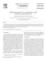
put in the middle of the tubular furnace. The side-view on the
heating system is schematically shown in Fig. 1a. The furnace
tube was evacuated for 5 min to reach the ultimate vacuum
(2 Pa) before the heating treatment, then high-pure Ar (99.99%)
was introduced into the tube at a flow rate of 40 sccm and kept
flowing, which maintained the furnace pressure at the normal
atmosphere pressure. The furnace temperature was then raised
to 1300 °C at a heating rate of 10 °C/min and held for 3 h.
Afterwards, the samples were cooled to room temperature at a
cooling rate of 10 °C/min in furnace with the protection of Ar.
In the next step, the Si wafer was taken out from Al
2
O
3
boat,
and Fe powders with the biggest size of 28 μm were put at the
upstream part of the Al
2
O
3
boat, then the Al
2
O
3
boat was placed
in the middle of the tubular furnace, as shown in Fig. 1b. The
tube was evacuated, filled with high-pure Ar and heated as
Materials Letters 61 (2007) 3783–3786
www.elsevier.com/locate/matlet
⁎
Corresponding author. Tel.: +86 22 81523700; fax: +86 22 27405874.
E-mail address: (X.W. Du).
0167-577X/$ - see front matter © 2007 Elsevier B.V. All rights reserved.
doi:10.1016/j.matlet.2006.12.033
described above until the furnace temperature rose to 750 °C,
then H
2
was filled at a flow rate of 10 sccm along with Ar gas.
Whereafter, the furnace temperature was raised to 1400 °C at a
heating rate of 10 °C/min and held for 3 h. Finally, the samples
were cooled at 10 °C/min in furnace with the protection of Ar
and H
2
to room temperature.
The morphology and structure were determined by FEI
Technai G
2
F20 TEM, and the composition was analyzed by
Oxford INCA energy-dispersive X-ray spectroscopy (EDS)
attached to the TEM. TEM samples were prepared by scratching
NWs from the wall of Al
2
O
3
boat and transferring onto copper
grids with carbon film.
3. Results and discussion
After the Si wafer was heated in Ar gas, a layer of megascopic wool-
like nanowires was found on Si wafer and the wall of the Al
2
O
3
boat.
Fig. 2a shows the TEM images of the generated nanowires. The
nanowires were 20–40 nm in diameter and several tens of microns in
length. The selected-area-electron-diffraction (SAED) pattern (inset in
Fig. 2a) on the nanowires reveals only diffusive rings, and no
diffraction spot was found, which indicates the amorphous nature of the
nanowires. Fig. 2b displays the EDS spectrum on the nanowires, which
contains the signals of Si, O, C and Cu elements. Considering the
nanowires were supported by a copper grid with carbon film in TEM
samples, C and Cu signals in EDS spectrum are not the intrinsic
information and can be neglected, therefore the product should be silica
NWs.
Fig. 1. Schematic diagram of the side-view on the system for synthesizing SiO
2
NWs (a) and that for synthesizing Fe NPs on SiO
2
NWs (b), respectively.
Fig. 2. (a) TEM image of the generated NWs and SAED pattern (inset); (b) EDS
spectrum of NWs.
Fig. 3. (a) High magnification TEM image of Fe NPs on SiO
2
NWs near the
initial Fe powders and SAED pattern (inset) of Fe NPs; (b) EDS spectrum on the
circle-marked area in (a).
3784 J. Sun et al. / Materials Letters 61 (2007) 3783–3786
Under the temperature 1300 °C, it is difficult for the silicon atoms in
wafer to escape by diffusion or sublimation, however, the tube furnace
was evacuated before the filling of highly pure Ar gas, and the partial
pressure of oxygen should be very low, and decrease with the reaction
time. As O
2
partial pressure is low enough (less than 10 Pa at 1300 °C),
atoms in bulk silicon could react with O
2
to form SiO gas [16],
2SiðsÞþO
2
ðgÞ→2SiOð gÞð1Þ
The SiO gas may condense anywhere in the tube furnace by the
following reaction,
SiOðgÞ→ Si
:
ðsÞþSiO
2
ðsÞð2Þ
As a result, Si/SiO
2
nanowires appear, and further oxidation of
nanowires could lead to the formation of pure SiO
2
nanowires.
After the Al
2
O
3
boat with SiO
2
NWs and Fe powders were heated in
H
2
and Ar mixture, many particles with the size of 3–20 nm appeared
on the surface of SiO
2
NWs, as shown in Fig. 3a. The inserted SAED
pattern exhibits clear rings corresponding to Fe {111}, {200}, {220},
{311}… planes. The EDS spectrum on the circle-marked area in Fig. 3a
(including Fe NPs and a silicon NW) is shown in Fig. 3b, and the result
suggests that there exist Fe, O, and Si elements. Compared with the
EDS spectrum on SiO
2
NWs shown in Fig. 2b, we can deduce that the
nanoparticles attaching on SiO
2
NWs are composed of Fe atoms.
To investigate the formation mechanism of Fe NPs, the distribution
and morphology of Fe NPs were analyzed in detail. In Fig. 4a, the dark
part in the lower-left corner shows an initial Fe particle with a size of
around 4 μm, and almost all the generated Fe NPs are on the side of
SiO
2
NWs facing to the initial Fe particle. Especially in Fig. 4c, Fe NPs
distribute on the surface of SiO
2
nanowire uniformly, and the size of Fe
NPs is close to the diameter of the nanowire, which approximates to
20 nm.
On the other hand, Fe NPs were only found on the SiO
2
NWs near
the initial Fe powders, as shown in Figs. 3a and 4, the density of Fe
nanoparticles decreases with the increase in the distance away from the
initial Fe powders, and finally Fe NPs disappear completely, as shown
in Fig. 2a.
The possible mechanisms on the formation of Fe NPs include
solid–liquid–solid (S–L–S) and S–V –S route. In the S–L–S route, the
solid massive Fe powders firstly melt and SiO
2
NWs are soaked in
liquid Fe; as temperature decreases, the layer of liquid Fe solidifies and
congregates into Fe NPs. In this case, the Fe NPs should distribute
uniformly on the surface of SiO
2
NWs; however, the experimental
result conflicts with this mechanism in two aspects: firstly, the massive
Fe powders should not melt at 1400 °C, and secondly, the Fe NPs do
not distribute uniformly and only appear on the front side facing to the
initial Fe powders.
As for the S–V–S route, when the temperature approaches 1400 °C,
the equilibrium vapor pressure between the solid phase and vapor
phase of Fe reaches to 0.437 Pa, calculated from the vapor–temperature
curve of Fe [17]. Therefore, the initial Fe powders sublimate into Fe
vapor in a rather high speed, and then Fe vapor is transported to the
surface of SiO
2
NWs by the flowing mixture of Ar and H
2
. Fe nuclei
form by the deposition and segregation of Fe atoms, and further growth
of Fe NPs proceeds with the continuous supply of Fe atoms during the
temperature-holding stage. Because the direction of the gas flow is
from the initial Fe powders to SiO
2
NWs, Fe atoms and Fe NPs only
attach on the front side of SiO
2
NWs, while no Fe NPs were found on
the back side of SiO
2
NWs.
4. Conclusion
Fe NPs dispersed on the surface of SiO
2
NWs can be
prepared simply by heating silicon wafer and Fe powders. The
nucleation and growth of Fe NPs follows the S–V–S
mechanism, where Fe powders firstly sublime and then the Fe
atoms deposit on SiO
2
nanowires to form Fe NPs. It is possible
to obtain various NWs decorated with NPs by changing the
starting materials. Our method is simple and efficient, thus
showing high potential on industrial application.
Acknowledgments
This work is financially supported by the Natural Science
Foundation of China (No. 50402010 and No. 50672065),
Natural Science Foundation of Tianjin City (No. 043800711)
and 985 Project of Tianjin University.
References
[1] G.L. Che, B.B. Lakshmi, E.R. Fisher, C.R. Martin, Nature 393 (1998)
346.
[2] K.Y. Jiang, A. Eitan, L.S. Schadler, P.M. Ajayan, R.W. Siegel, Nano Lett. 3
(2003) 275.
[3] M. Endo, Y.A. Kim, M. Ezaka, K. Osada, T. Yanagisawa, T. Hayashi, M.
Terrones, M.S. Dresselhaus, Nano Lett. 3 (2003) 723.
[4] C.L. Sun, L.C. Chen, M.C. Su, L.S. Hong, O. Chyan, C.Y. Hsu, K.H.
Chen, T.F. Chang, L. Chang, Chem. Mater. 17 (2005) 3749.
Fig. 4. TEM image of Fe NPs on SiO
2
NWs; (a) the area near an initial Fe particle; (b) the area apart from initial Fe powders; (c) a SiO
2
nanowire with separated Fe
NPs.
3785J. Sun et al. / Materials Letters 61 (2007) 3783–3786
[5] M. Olek, T. Büsgen, M. Hilgendorff, M. Giersig, J. Phys. Chem., B 110
(2006) 12901.
[6] A.D. LaLonde, M.G. Norton, D. Zhang, D. Gangadean, A. Alkhateeb, R.
Padmanabhan, D.N. McIlroy, J. Nanopart. Res. 8 (2006) 99.
[7] J. Sharma, J.P. Vivek, K.P. Vijayamohanan, P. Singh, C.V. Dharmadhikari,
Appl. Phys. Lett. 88 (2006) 193103.
[8] A.A. Yasseri, S. Sharma, T.I. Kamins, Z. Li, R.S. Williams, Appl. Phys., A
Mater. Sci. Process. 82 (2006) 659.
[9] X.H. Sun, N.B. Wong, C.P. Li, S.T. Lee, P.S.G. Kim, T.K. Sham, Chem.
Mater. 16 (2004) 1143.
[10] Y.Q. Qu, R. Porter, F. Shan, J.D. Carter, T. Guo, Langmuir 22 (2006) 6367.
[11] X.H. Sun, H.Y. Peng, Y.H. Tang, W.S. Shi, N.B. Wong, C.S. Lee, S.T. Lee,
T.K. Sham, J. Appl. Phys. 89 (2001) 6396.
[12] X.H. Sun, R. Sammynaiken, S.J. Naftel, Y.H. Tang, P. Zhang, P.S. Kim,
T.K. Sham, X.H. Fan, Y.F. Zhang, C.S. Lee, S.T. Lee, N.B. Wong, Y.F.
Hu, K.H. Tan, Chem. Mater. 14 (2002) 2519.
[13] X.H. Sun, C.P. Li, N.B. Wong, C.S. Lee, S.T. Lee, B.K. Teo, Inorg. Chem.
41 (2002) 4331.
[14] Q. Zhao, M.B. Nardelli, W. Lu, J. Bernholc, Nano Lett. 5 (2005) 847.
[15] W. Lesniak, A.U. Bielinska, K. Sun, K.W. Janczak, X.Y. Shi, J.R. Baker
Jr., L.P. Balogh, Nano Lett. 5 (2005) 2123.
[16] X.W. Du, X. Zhao, S.L. Jia, J.J. Li, N.Q. Zhao, Mater. Sci. Eng., B, Solid-
State Mater. Adv. Technol. 136 (2006) 72.
[17] R.E. Honig, D.A. Kramer, RCA Rev. 30 (1969) 285.
3786 J. Sun et al. / Materials Letters 61 (2007) 3783–3786