- Trang chủ >>
- Khoa Học Tự Nhiên >>
- Vật lý
Raman spectroscopy and field electron emission properties of aligned silicon nanowire arrays
Bạn đang xem bản rút gọn của tài liệu. Xem và tải ngay bản đầy đủ của tài liệu tại đây (457.69 KB, 5 trang )
Physica E 30 (2005) 169–173
Raman spectroscopy and field electron emission properties of aligned
silicon nanowire arrays
Chun Li
a
, Guojia Fang
a,Ã
, Su Sheng
a
, Zhiqiang Chen
a
, Jianbo Wang
b
,
Shuang Ma
a
, Xingzhong Zhao
a
a
Department of Physics and Center of Nanoscience and Nanotechnology Research, Wuhan University, Wuhan, 430072, PR China
b
Center for Electron Microscopy, Wuhan University, Wuhan, 430072, PR China
Received 20 March 2005; received in revised form 22 August 2005; accepted 30 August 2005
Available online 7 October 2005
Abstract
Arrays of aligned silicon nanowire (SiNW) were synthesized on a silicon (1 0 0) substrate by self-assembling electroless
nanoelectrochemistry. Compared with that of bulk crystal silicon, the first-order Raman peak of the silver cap-removed SiNW arrays
shows a downshift and asymmetric broadening due to the phonon quantum confinement effects, and intensity enhancement. Field
electron emission from the SiNWs was also investigated. The turn-on field was found to be about 12 V/mm at a current density of
0.01 mA/cm
2
. These highly densified and ordered SiNW arrays can be expected to have favorable applications in vacuum electronic or
optoelectronic devices.
r 2005 Elsevier B.V. All rights reserved.
PACS: 71.55.Cn; 85.45.Db; 78.30.Àj
Keywords: Silicon nanowire; Electroless metal deposition; Field emission; Raman spectra
1. Introduction
One-dimensional nanostructure materials are expected
to play an important role as both interconnects and
functional units in fabricating electronic and optoelectronic
devices with nanoscale dimensions [1]. SiNWs have
attracted increasing attention due to their novel funda-
mental physical properties such as light emission [2], field
electron emis sion [3], and quantum confinement effects [4].
Applications based on SiNW have been demonstrated in
field-effect transistors [5], logic circuits [6], chemical and
biological sensors [7], and thin film transistors [8]. To date,
SiNWs have been prepared by chemical vapor deposition
[9,10], laser ablation [3,11], thermal evaporation [12],
template-assisted growth [13], oxide-assisted growth
(OAG) [14] and other methods [15]. The SiNWs exhibit a
unique sp
3
-bonded crystal structure and a low work
function. Field electron emission properties of taperlike
SiNWs [14], sponge-like SiNW-induced films [3], and well-
aligned SiNWs [16] have been reported. However, these
growth mechanisms have some limitations including high
temperature or vacuum conditions, special templates and
complex equipments. A simple and efficient way to
fabricate large-scale, highly oriented, and length-control-
lable SiNWs at a lower temperature is an important and
challenging issue. Recently, electroless metal deposition
(EMD) method was developed to prepare lager-area
oriented SiNWs arrays on silicon substrates close to room
temperature [17,18]. However, the metal is always capped
on SiNWs during the preparation procedure [19] and little
information has been reported on the physical properties of
such aligned single-crystal SiNW arrays.
In this work, SiNW arrays have been synthesized by self-
assembly of EMD nanoelectrochemistry. The silver nano-
caps were removed by post-deposition treatment with nitric
acid solution. Afterwards, Raman spectroscopy and field
electron emission properties were studied.
ARTICLE IN PRESS
www.elsevier.com/locate/physe
1386-9477/$ - see front matter r 2005 Elsevier B.V. All rights reserved.
doi:10.1016/j.physe.2005.08.005
Ã
Corresponding author. Tel.: +86 27 87642784; fax: +86 27 68752569.
E-mail address: (G. Fang).
2. Experimental details
The synthesis of aligned SiNWs array was carried out in
a Telfon-lined stainless-steel autoclave. The n-type, Sb-
doped silicon (1 0 0) (resistivity $0.02 Ocm) wafer was
cleaned ultrasonically in acetone and ethanol for 20 min
each. The cleaned silicon wafer was immersed in a mixture
of 4.6 mol/L HF aqueous solution and 0.02 mol/L silver
nitrate with equal volume. Then, the au toclave was sealed
and transferred to a lab oven immediately. After etching
for 60 min at 50 1C, the silicon wafer wrapped with a thick
silver film was taken out from the autoclave. To remove the
capped silver, the as-prepared samples were dipped in
30 wt% HNO
3
aqueous solution for 60 s. Finally, the as-
prepared sampl es and the treated ones were rinsed with de-
ionized water, blown dry in air and subjected to further
analysis.
Sirion FEG (Philips XL30) scanning electron micro-
scopy (SEM) attached with an energy-dispersive X-ray
spectrometer (EDXS, Genesis7000 EDAX) was used to
study the morphology and chemical composition of the
samples. The transmission electron microscopy (TEM) and
the high-resolution transmission electron microscopy
(HRTEM) images were obtained with a JEOL JEM-2010
(HT) and a JEOL 2010F microscope, respectively. The
samples wer e prepared by ultrasonicating the nanowi res in
ethanol and placing a drop of the suspension on a TEM
carbon support film. Raman scattering measurements were
performed using a Renishaw (RMRe1000) micro-Raman
spectrometer at room temperature. Raman scattering
modes were excited by means of the 514 nm line of an
Ar
+
laser, and the Raman signals were measured in a
backscattering geometry with a spectral resolution of
1.0 cm
À1
. Field emission behavior was investigated using
a diode structure with an anode–cathode spacing of 50 mm
in a test chamber maintained at 10
À4
Pa. A spherical-
shaped stainless-steel probe with a tip diameter of 1 mm
was used as an anode.
3. Results and discussion
Fig. 1 shows typical SEM images of the as-prepared
samples an d SiNW arrays after being treated with an
HNO
3
solution. The branched dendritic structure of silver
on the top of SiNWs is shown in Fig. 1a and b. The tilted
301 view image shows that the SiNWs are closely
interconnected and held together in bundles (Fig. 1c). This
phenomenon is usual for nanosize materials caused by Van
der Waals interaction. As can be seen from the side view
(Fig. 1d), the nanowires are all straight, uniform and
relatively vertical to the silicon substrate. Their length can
be determined to be about 10 mm. The EDX spectrum of
the SiNWs after treatment with HNO
3
compared with that
of as-prepared samples reveals only one strong peak
corresponding to silicon, which indicates that silver was
removed completely (Fig. 2a and b). Further struc tural
characterization of the SiNWs was performed with TEM
and HRTEM. Fig. 3 shows a typical individual nanowire
ARTICLE IN PRESS
Fig. 1. SEM images of as-prepared and treated SiNWs. (a), (b) As-prepared SiNWs capped with silver (the dendritic structure of a silver cap); (c), (d) tilted
301 view and side view of post-deposition-treated SiNWs, respectively.
C. Li et al. / Physica E 30 (2005) 169–173170
40 nm wide and 10 mm in length. No metal particles were
observed at the side, top or bottom of the wires. The top
left inset in Fig. 3 shows the selected-area electron
diffraction pattern (SAED) of the corresponding nanowire
with the electron beam parallel to the [310] zone axis, which
proves its silicon crystalline nature. SAED and HRTEM
confirm that the length direction of the nanowire is along
[0 0 1]. The interplanar spacing between the visible fringer is
0.28 nm, corresponding to the (0 0 2) plane of silicon. There
is a thin amorphou s layer sheathing the crystalline core of
the SiNW (bottom right inset in Fig. 3), which is identified
to be amorphous silicon oxide (SiO
x
) resulting from surface
oxidation.
The formation mechanism of aligned SiNWs arrays can
be understood as being a self-assembly metal nanoden-
drite-assisted etching process with a localized microscopic
nanoelectrochemical cell model [20]. The deposited silver
nanoclusters are uniformly distributed throughout the
surface of the silicon wafer at the initial stage. Self-
assembly of silver nanoclusters to the dendrite structure
and lack of coalescence to a compact grain film continue to
cause etching of the silicon wafer along one direction in the
AgNO
3
–HF solution. At the end of the etching process, the
wire structure is formed.
The Raman spectra of bulk single-crystal silicon (c-Si)
and SiNWs are shown in Fig. 4. A Raman peak at
520.2 cm
À1
with the full-width at half-maximum (FWHM)
of 4.6 cm
À1
can be seen in the Raman spectrum of c-Si,
which can be attributed to the scattering of the first-order
optical phonon (TO) of c-Si [21]. In comparison, the first-
order Ram an peak of SiNWs is at 516.2 cm
À1
with an
FWHM of 14.2 cm
À1
(a downshift by 4 cm
À1
). Its linewidth
is broadened and the line shape becomes increasingly
asymmetric with an extended tail at low frequencies
(Fig. 4). Qualitatively, when the crystalline size decreases,
momentum conservation will be relaxed ðqa0Þ and
ARTICLE IN PRESS
Fig. 2. EDXS of SiNW arrays. (a) As-prepared sample; (b) sample after
treatment with HNO
3
.
Fig. 3. TEM image of an individual SiNW with the corresponding SAED pattern (top left) in the inset. The bottom right inset shows an HRTEM image
of a SiNW.
C. Li et al. / Physica E 30 (2005) 169–173 171
Raman-active modes will not be limited to being at the
center of the Brillouin zone (G point). The smaller the
crystalline grain, the larger the frequency shifts and the
more asymmetric and the broader the peak becomes. This
feature has been confirmed by experiments on nano-
crystalline silicon [22] and porous silicon [23] and SiNWs
fabricated by thermal evaporation [12]. According to the
theoretical model proposed by Richter et al. [24] and
Campbell et al. [25], the first-order Raman spectrum can be
described by the following equation:
IðoÞ¼
Z
d
3
qCð0; qÞ
2
½o À oðqÞ
2
þ
G
0
2
ÀÁ
2
, (1)
where the phonon wave vector q is expressed in units of
2p=a, the crystalline grain size L is in units of a, with a
being the lattice constant of silicon and o(q) represents the
phonon dispersion curve. G
0
is the geometrical sum of the
inverse lifetime of zone center phonon and there is an
increase of the linewidth by phonon dispersion. C is the
weighting function in reciprocal space, which can be chosen
by physical arguments only [4]. Using this model, the
experiment data were fitted well by choosing it as
jCð0; qÞj
2
¼ expðÀq
2
L
2
=4p
2
Þ with L ¼ 10 nm as shown in
Fig. 4. In addition, about 10-times enhancement of first-
order Raman spectrum compared with that of c-Si was
observed, which is shown in the inset of Fig. 4. Two effe cts
could lead to the enhancement of Raman intensity. Firstly,
the transmitted excitation intensity into the material should
increase according to decreasing area fraction of the
remaining silicon after etching, ignoring losses to diffuse
scattering. Secondly, the Raman backscatter traveling
toward the surface may have encountered the nano-
interstice surface between the SiNWs, suggesting another
enhancement factor for the light excitation [26].
It is well known that cold cathode field electron emission
is one of the most important and promising applications of
nanoscale tubes or wires with sharp tip arrays. For field
electron emission devices, the desired tip diameter of the
SiNWs must be less than 100 nm, and the aspect ratio must
be higher than 10 [16]. In this work, SiNWs with an aspect
ratio higher than 200 have been successfully synthesized.
The EMD method enables one to control the size and
aspect ratio of SiNWs through deposition parameters
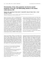
[17–20]. Fig. 5 shows the results of current density versus
anode–cathode voltage (I–V) with the inset being the
corresponding Fowler–Nordheim (FN) plot [ln ðJ=E
2
Þ
versus 1=E]. The FN plot shows that the measured data fit
well to the linear relationship given by the following
equation:
lnðJ=E
2
l
Þ¼lnðA=fÞÀBf
3=2
=E
l
, (2)
with two distinct regions , where A ¼ 1:54 Â 10
À6
AeVV
À2
,
B ¼ 6:83 Â 10
3
eV
À3=2
Vmm
À1
, J is the current density, b is
the field enhancement factor, and F is the work function of
emitter materials. The local electric field (E
l
) can be related
to b and the macroscopic field (E
m
)byE
l
¼ bE
m
¼ bV =d,
where V is the applied voltage, and d is the distance
between the cathode and the anode. The field enhancement
factor can be de termined from the slope of the FN plot, if
the work function of the emitter is known. Assuming that
F equals 4.15 eV for Si [27], b was calculated to be 1270 and
616 from the slope of the fitted lines (a) and (b),
respectively. Clearly, the field emission from SiNWs
underlies a barrier tunneling quantum mechanical mechan-
ism. The change of the slope of the FN plot from the low-
field to the high-field region indicates that the local field
conditions at the top of the nanowire may not always be
linearly dependent on the applied voltage during the whole
voltage sweeping [28]. After cond ucting the same electric
field sweeping at least 10 times, no considerable change was
found. The turn-on field, which we de fine as the electric
field required to detect a current density of 0.01 mA/cm
2
,is
estimated to be about 12 V/mm. This value is comparable
with those for other field emitters including carbon
nanotubes [29], diamonds [30] and SiNWs fabricated by
the laser-ablation method [3], chemical vapor deposition
[9], oxide-assisted growth [14], and vapor–liquid–solid
ARTICLE IN PRESS
Fig. 4. Raman spectra of signals normalized to the same peak height to
illustrate shift and asymmetric broadening. The inset shows the signals
from bulk c-Si and SiNWs.
Fig. 5. Emission current–voltage characteristics of SiNWs. The inset
shows Fowler–Nordheim plots of ln(J/E
2
) versus (1/E).
C. Li et al. / Physica E 30 (2005) 169–173172
(VLS) method [31]. As this rapid synthesis method is not
inherently area limited, possesses lower growth tempera-
ture and can be scaled up with the reaction vessel size and
may also be compatible with standard lithographic
processes, this kind of SiNW arrays have potential
application in field emission microelectronic devices.
4. Conclusions
A relatively rapid (a growth rate greater than 3 nm/s)
and inexpensive method of fabricating large-area silver
cap-removed SiNWs has been demonstrated on the basis of
an electroless metal deposition technique. The single-
crystal SiNWs show a high aspect ratio greater than 200
with an average diameter of 40 nm. The phonon quantum
confinement effects of the SiNW arrays were confirmed
through the downshifting, broadening and asymmetry of
the first-order Raman peak. A goo d fie ld electron emission
for SiNWs was observed with a turn-on field of 12 V/mmat
a current density of 0.01 mA/cm
2
. This kind of SiNW
directly formed on a silicon substrate would be of
particular interest for integration in the current silicon-
technology-based vacuum electronic and optoelectronic
devices.
Acknowledgements
This work was supported by the National Natural
Science Foundation of China under Grant No. 60244003 .
References
[1] Y.N. Xia, P.D. Yang, Y.G. Sun, Y.Y. Wu, B. Mayers, B. Gates, Y.D.
Yin, F. Kim, H.Q. Yan, Adv. Mater. 13 (2003) 353.
[2] J.F. Qi, J.M. White, A.M. Belcher, Y. Masumoto, Chem. Phys. Lett.
372 (2003) 763.
[3] F.C.K. Au, K.W. Wong, Y.H. Tang, Y.F. Zhang, I. Bello, S.T. Lee,
Appl. Phys. Lett. 75 (1999) 1700.
[4] S. Bhattacharyya, S. Samui, Appl. Phys. Lett. 84 (2004) 1564.
[5] Y. Cui, Z. Zhong, D. Wang, W. Wang, C.M. Lieber, Nano Lett. 3
(2003) 149.
[6] Y. Huang, X. Duan, Y. Cui, L. Lauhon, K. Kim, C.M. Lieber,
Science 294 (2001) 1313.
[7] Y. Cui, Q. Wei, H. Park, C.M. Lieber, Science 293 (2001) 1289.
[8] X. Duan, C. Niv, V. Sahi, J. Chen, J.W. Parce, S. Empedocles, J.L.
Goldman, Nature 425 (2003) 274.
[9] M. Lu, M.K. Li, L.B. Kong, X.Y. Guo, H.L. Li, Chem. Phys. Lett.
374 (2003) 542.
[10] T.I. Kamins, R.S. Williams, Y. Chen, Y.L. Chang, Y.A. Chang,
Appl. Phys. Lett. 76 (2000) 562.
[11] D.P. Yu, C.S. Lee, I. Bello, G.W. Zhou, Z.G. Bai, Z. Zhang, S.Q.
Feng, Solid State Commun. 105 (1998) 403.
[12] D.P. Yu, Z.G. Bai, Y. Ding, Q.L. Hang, H.Z. Zhang, J.J. Wang,
Y.H. Zou, W. Qian, G.C. Xiong, H.T. Zhou, S.Q. Feng, Appl. Phys.
Lett. 72 (1998) 3458.
[13] K.K. Lew, J.M. Redwing, J. Cryst. Growth 254 (2003) 14.
[14] Y.L. Chueh, L.J. Chou, S.L. Cheng, J.H. He, W.W. Wu, L.J. Chen,
Appl. Phys. Lett. 83 (2005) 133112.
[15] J.D. Holmes, K.P. Johnston, R.C. Doty, B.A. Korgel, Science 287
(2000) 1471.
[16] M. Ishida, T. Kawano, M. Futagawa, Y. Arai, H. Takao, K. Sawada,
Superlattice Microstruct. 34 (2003) 567.
[17] K.Q. Peng, J. Zhu, J. Electroanal. Chem. 558 (2003) 35.
[18] K.Q. Peng, J. Zhu, Electrochim. Acta 49 (2004) 2563.
[19] T. Qiu, X.L. Wu, X. Yang, G.S. Huang, Z.Y. Zhang, Appl. Phys.
Lett. 84 (2004) 3867.
[20] K.Q. Peng, Y.J. Yan, S.P. Gao, J. Zhu, Adv. Mater. 14 (2002) 1164.
[21] B.B. Li, D.P. Yu, S.L. Zhang, Phy. Rev. B 59 (1999) 1645.
[22] Z. Iqbal, S. Veperk, J. Phys. C 15 (1982) 377.
[23] Z.F. Sui, P.P. Leong, I.P. Herman, G.S. Higashi, H. Temkin, Appl.
Phys. Lett. 60 (1992) 2086.
[24] H. Richter, Z.P. Wang, L. Ley, Solid State Commun. 39 (1981) 625.
[25] I.H. Campbell, P.M. Fauchet, Solid State Commun. 58 (1986) 739.
[26] L. Tian, K.B. Ram, I. Ahmad, L. Menon, M. Holtz, J. Appl. Phys. 97
(2005) 026101.
[27] C.S. Chang, S. Chattopadhyay, L.C. Chen, K.H. Chen, C.W. Chen,
Y.F. Chen, R. Collazo, Z. Sitar, Phy. Rev. B 68 (2003) 125322.
[28] Y.C. Choi, Y.M. Shin, D.J. Bae, S.C. Lim, Y.H. Lee, B.S. Lee, Diam.
Relat. Mater. 10 (2001) 1457.
[29] Q.H. Wang, T.D. Corrigan, J.Y. Dai, R.P.H. Chang, A.R. Krauss,
Appl. Phys. Lett. 70 (1997) 3308.
[30] W. Zhu, G.P. Kochansiki, S. Jin, L. Seibles, D.C. Jacobson, M.
McCormack, A.E. White, Appl. Phys. Lett. 67 (1995) 1157.
[31] J. Westwater, D.P. Gosain, S. Tomiya, S. Usui, H. Ruda, J. Vac. Sci.
Technol. B 15 (1997) 554.
ARTICLE IN PRESS
C. Li et al. / Physica E 30 (2005) 169–173 173