Conventional Three-Phase Fixed-Bed Technologies: Analysis and Critique docx
Bạn đang xem bản rút gọn của tài liệu. Xem và tải ngay bản đầy đủ của tài liệu tại đây (7.28 MB, 115 trang )
SpringerBriefs in Applied Sciences
and Technology
For further volumes:
/>Leonid B. Datsevich
Conventional Three-Phase
Fixed-Bed Technologies
Analysis and Critique
123
Leonid B. Datsevich
University of Bayreuth
Bayreuth
Germany
and
MPCP GmbH
Bayreuth
Germany
ISSN 2191-530X ISSN 2191-5318 (electronic)
ISBN 978-1-4614-4835-8 ISBN 978-1-4614-4836-5 (eBook)
DOI 10.1007/978-1-4614-4836-5
Springer New York Heidelberg Dordrecht London
Library of Congress Control Number: 2012943362
Ó The Author(s) 2012
This work is subject to copyright. All rights are reserved by the Publisher, whether the whole or part of
the material is concerned, specifically the rights of translation, reprinting, reuse of illustrations,
recitation, broadcasting, reproduction on microfilms or in any other physical way, and transmission or
information storage and retrieval, electronic adaptation, computer software, or by similar or dissimilar
methodology now known or hereafter developed. Exempted from this legal reservation are brief
excerpts in connection with reviews or scholarly analysis or material supplied specifically for the
purpose of being entered and executed on a computer system, for exclusive use by the purchaser of the
work. Duplication of this publication or parts thereof is permitted only under the provisions of
the Copyright Law of the Publisher’s location, in its current version, and permission for use must always
be obtained from Springer. Permissions for use may be obtained through RightsLink at the Copyright
Clearance Center. Violations are liable to prosecution under the respective Copyright Law.
The use of general descriptive names, registered names, trademarks, service marks, etc. in this
publication does not imply, even in the absence of a specific statement, that such names are exempt
from the relevant protective laws and regulations and therefore free for general use.
While the advice and information in this book are believed to be true and accurate at the date of
publication, neither the authors nor the editors nor the publisher can accept any legal responsibility for
any errors or omissions that may be made. The publisher makes no warranty, express or implied, with
respect to the material contained herein.
Printed on acid-free paper
Springer is part of Springer Science+Business Media (www.springer.com)
Preface
Three reasons inspired the author to write this monograph. The first reason is the
obvious drawbacks inherent in the available literature devoted to industrial mul-
tiphase fixed-bed technologies. As a rule, the interactions between the physical and
chemical phenomena are not comprehensively analyzed although an experienced
reader can find a great number of publications where specific features of industrial
reactors related to hydrodynamics, kinetics, mass, and heat transfer are described
in detail.
Additionally, existing books suffer from a lack of the genesis of the technical
solutions and, therefore, cannot pronounce the new technological perspectives that
may motivate the development of more advanced techniques. Maybe, the absence
of such narration in these books accounts for the reign of the technological par-
adigms applied to the conventional fixed-bed processes. At least for about
80 years, there have been no significant attempts to reconsider the old concepts
formulated by the previous generation of process developers.
The second reason to write the monograph partly followed from the first one.
Being involved in the development of new multiphase processes and discovery of
unknown catalytic phenomena, the author could not understand why some pro-
fessionals engaged in academic research, industrial development and operation
rejected to conceive the ideas that, in the author’s opinion, were not so compli-
cated and had been proved not only in experimental units, but also in industrial
installations. The explanation of such a rather strange fact lies apparently in that
the traditional approaches are regarded as the undoubted postulates, even if under a
close view, they turn out to be false. The monograph explains why these deeply
rooted, but wrong approaches will be ineffective and even dangerous if they are
realized in industrial plants. Thus, one of the objectives of this book is to help
specialists to comprehend the misconceptions in scientific and design approaches
as well as to indicate that some attempts to enhance industrial processes are dead-
end and futureless––with no chance to succeed when these efforts follow the
stereotypes embedded in the traditional literature. Additionally, the focal point of
this work is to show why the conventional paradigms do not correspond to the
current level of scientific and technical knowledge.
v
Finally, the third purpose of writing this book is to summarize the latest
achievements related to new multiphase technologies and theories. Since some of
these technologies were of dual use, their technical solutions in design could not be
presented in detail earlier. The same restrictions were partly imposed upon
the disclosure of the scientific fundamentals lying in their base. Although the
description of some parts of these theories and technological solutions can be
found in professional journals, their full extent is presented in this work for the first
time. The author hopes that the presentation of this first-hand knowledge about the
GIPKh and POLF technologies, Two-Zone Model, Oscillation theory, energy
dissipation mapping and analysis of runaways as well as the lessons learnt from the
revision of the old techniques can initiate fruitful discussions among professionals
and motivate young researchers and practical engineers to go beyond the tradi-
tional paradigms.
The author points out that it is impossible to cover all aspects of multiphase
fixed-bed reactors in one book. Therefore, the narration is concentrated on the
most significant features important for the critical revision of the conventional
processes with respect to intensification efforts, efficiency of the energy utilization,
bottlenecks inherent in the industrial design, and process safety, regardless of the
applications of new types of catalysts (monolith, regular packing, etc.). The author
also tried not to overburden the text with the detailed technical specifications,
equations, correlations and references, which were not necessary for the under-
standing of the crucial issues.
In many respects, the idea to write this book was induced by the author’s
opponents involved in the process development, design, operation, and the man-
ufacture of equipment as well as the author’s co-workers and Ph.D. students. The
author expresses his deep appreciation to all of these people for the arguments born
during their battles, many of which can be found in this work.
The author is greatly indebted to his colleagues from RSC ‘‘Applied
Chemistry’’ (St. -Petersburg, Russia), the University of Bayreuth and MPCP
GmbH (Bayreuth, Germany) for the support and discussions. The author would
like to mention some of them here: H. M. Avanesova, O. D. Ignatieva,
M. P. Kambur, G. A. Mironova, D. A. Mukhortov, M. I. Nagrodskii,
Y. V. Sharikov, O. J. Sokolova, N. G. Zubritskaya, B. Battsengel, A. Jess, S. Fritz,
T. Oehmichen, C. Schmitz, W. Wache, S. Werth, P. Dallakian, F. Grosh,
R. Wolfrum.
vi Preface
Contents
1 Introduction 1
References . . . . . . . . . . . . . . . . . . . . . . . . . . . . . . . . . . . . . . . . . 6
2 Technological Reasons for the Selection
of Fixed-Bed Reactors 7
3 Traditional Approaches to the Design of Fixed-Bed Reactors 11
3.1 Approaches from the Point of View of Kinetics . . . . . . . . . . . 12
3.2 Approaches from the Point of View of External
Mass Transfer . . . . . . . . . . . . . . . . . . . . . . . . . . . . . . . . . . 17
3.3 Approaches from the Point of View of Heat Evolution . . . . . . 20
3.4 Approaches from the Point of View of Hydrodynamics. . . . . . 22
3.5 Concluding Remarks. . . . . . . . . . . . . . . . . . . . . . . . . . . . . . 23
References . . . . . . . . . . . . . . . . . . . . . . . . . . . . . . . . . . . . . . . . . 24
4 Process Flow Diagram and Principal Embodiments
of Conventional Industrial Units 25
References . . . . . . . . . . . . . . . . . . . . . . . . . . . . . . . . . . . . . . . . . 31
5 Analysis of Conventional Industrial Processes 33
5.1 Temperature Control and Heat Balance . . . . . . . . . . . . . . . . . 34
5.2 Loop Hydraulics as the Main Factor for a Choice
of the Operating Pressure . . . . . . . . . . . . . . . . . . . . . . . . . . 36
5.3 Macrokinetic Peculiarities . . . . . . . . . . . . . . . . . . . . . . . . . . 39
5.4 Phenomenology of Gas–Liquid Flow . . . . . . . . . . . . . . . . . . 43
5.5 Mass Transfer . . . . . . . . . . . . . . . . . . . . . . . . . . . . . . . . . . 45
5.5.1 Mass Transfer Coefficients . . . . . . . . . . . . . . . . . . . . 45
5.5.2 Two-Zone Model for an Active Catalyst . . . . . . . . . . . 47
5.6 Specific Productivity of the Catalyst Bed . . . . . . . . . . . . . . . 51
vii
5.7 Is the Energy Delivered to the Reactor System
Dissipated Effectively? . . . . . . . . . . . . . . . . . . . . . . . . . . . . 53
5.8 Process Safety . . . . . . . . . . . . . . . . . . . . . . . . . . . . . . . . . . 55
5.9 Approximate Algorithm of the Research
and Design Procedures . . . . . . . . . . . . . . . . . . . . . . . . . . . . 58
5.10 Concluding Remarks. . . . . . . . . . . . . . . . . . . . . . . . . . . . . . 60
References . . . . . . . . . . . . . . . . . . . . . . . . . . . . . . . . . . . . . . . . . 61
6 Purification Processes 63
References . . . . . . . . . . . . . . . . . . . . . . . . . . . . . . . . . . . . . . . . . 64
7 Do the Conventional Fixed-Bed Reactors Possess any Potential
for the Process Intensification? 65
Reference . . . . . . . . . . . . . . . . . . . . . . . . . . . . . . . . . . . . . . . . . . 67
8 Unsteady-State Operation (Feed Modulations) as an Attempt
to Intensify Processes: Can it be Applied on a Great Scale? 69
References . . . . . . . . . . . . . . . . . . . . . . . . . . . . . . . . . . . . . . . . . 71
9 Alternative Industrial Fixed-Bed Technologies 73
9.1 GIPKh Technology . . . . . . . . . . . . . . . . . . . . . . . . . . . . . . . 74
9.1.1 Process Flow Diagram and Principal Embodiments . . . 74
9.1.2 Temperature Control and Heat Balance. . . . . . . . . . . . 78
9.1.3 Why were the Reactors with a Liquid Loop Not
Considered for Industrial Applications Earlier? . . . . . . 79
9.1.4 Hydrodynamic and Mass Transfer Aspects
of the GIPKh Reactors . . . . . . . . . . . . . . . . . . . . . . . 80
9.1.5 Approximate Algorithm of the Research
and Design Procedures . . . . . . . . . . . . . . . . . . . . . . . 82
9.1.6 Comparison of the GIPKh Technology
with the Conventional Processes . . . . . . . . . . . . . . . . 83
9.2 POLF Technology . . . . . . . . . . . . . . . . . . . . . . . . . . . . . . . 85
9.2.1 Scientific Fundamentals of the POLF Technology . . . . 85
9.2.2 Process Flow Diagram and Principal Embodiments . . . 87
9.2.3 Choice of Process Variables . . . . . . . . . . . . . . . . . . . 89
9.2.4 Phenomenology of Mono Phase Flow
and Liquid Solid Mass Transfer . . . . . . . . . . . . . . . . . 90
9.2.5 Approximate Algorithm of the Research
and Design Procedures . . . . . . . . . . . . . . . . . . . . . . . 91
9.2.6 Comparison of the POLF Technology with
the Conventional Fixed-Bed Reactors . . . . . . . . . . . . . 92
9.3 Concluding Remarks. . . . . . . . . . . . . . . . . . . . . . . . . . . . . . 94
References . . . . . . . . . . . . . . . . . . . . . . . . . . . . . . . . . . . . . . . . . 94
viii Contents
10 Conclusions and Perspectives 97
References . . . . . . . . . . . . . . . . . . . . . . . . . . . . . . . . . . . . . . . . . 98
Appendix A: Evaluation of an Incorporated Heat Exchanger
Destined for the Complete Heat Withdrawal
from a Catalyst Bed 99
Appendix B: Energy Demand for the Compression
and Transportation of Gas 103
Index 105
Contents ix
List of Symbols
a
s
Specific external area of catalyst particles in the bed (external surface
area of catalyst particles per bed volume), m
-1
C
A,0
Concentration of the liquid reactant in the liquid feed, mol/m
3
C
A,cat
Concentration of a liquid reactant in the catalyst bulk, mol/m
3
C
A,in
Concentration of a liquid reactant at the reactor inlet in the GIPKH and
POLF technologies (after mixing with the recirculated product),
mol/m
3
C
A,inv
Concentration of a liquid reactant according to Eq. (5.19), mol/m
3
C
A,l
Concentration of a liquid reactant in the liquid bulk, mol/m
3
C
A,out
Concentration of the liquid reactant at the outlet of the reactor or
catalyst bed, mol/m
3
C
A,out
(1)
Concentration of the liquid reactant at the outlet of the first catalyst bed
in the two-stage POLF technology (Fig. 9.4b), mol/m
3
C
A,out
(2)
Concentration of the liquid reactant at the outlet of the second catalyst
bed in the two-stage POLF technology (Fig. 9.4b), mol/m
3
C
A,s
Concentration of a liquid reactant on the external catalyst surface, mol/m
3
DC
A
Concentration drop of the liquid reactant DC
A
¼
1
n
C
B;g
H
, mol/m
3
C
B;cat
Concentration of a gas compound in the catalyst bulk, mol/m
3
C
B,g
Concentration of a gas compound in the gas phase, mol/m
3
C
B,g
*
Equilibrium concentration of a gas compound on the gas side of the
gas–liquid interface, mol/m
3
C
B,l
Concentration of a gas compound in the liquid bulk, mol/m
3
C
Ã
B;l
Equilibrium concentration of a gas compound on the liquid side of the
gas–liquid interface, mol/m
3
C
B,out
Concentration of the gas reactant at the outlet of the reactor in the one-
stage POLF process (Fig. 9.4a), mol/m
3
C
B,s
Concentration of a gas compound on the external catalyst surface (in
the liquid phase), mol/m
3
C
P,g
Molar heat capacity of the gas phase for constant pressure, J/(mol K)
xi
C
P,l
Specific heat of the liquid phase for constant pressure, J/(kg K)
C
V,g
Specific heat of the gas phase for constant volume, J/(mol K)
d
cat
Diameter of a catalyst particle, m
d
HE
Tube diameter of an incorporated heat exchanger (Appendix A), m
d
tube
Tube diameter, m
D
A,l
Diffusivity of a liquid compound in the liquid phase, m
2
/s
D
B,eff
Effective diffusion coefficient of gas inside the catalyst pellet, m
2
/s
D
B,l
Diffusivity of a gaseous compound in the liquid phase, m
2
/s
D
r
Diameter of reactor, m
E Power demanded for gas compressing or power lost at gas transpor-
tation, W
E
recycle
Estimated power demanded for gas recycling by the recycle compres-
sor (Table 3.2), W
F
HE
Heat transfer surface of an incorporated heat exchanger (Appendix A),
m
2
F
reactor
Cross-sectional surface of the catalyst bed, m
2
g Acceleration of gravity, g = 9.81 m/s
2
G.S. Surplus of the gas compound over the liquid reactant (Eq. (5.16))
H Henry’s coefficient (C
Ã
B;g
¼ HC
Ã
B;l
)
ÀDH
A
Reaction heat related to liquid compound (ÀDH
A
¼ÀnDH
B
), J/mol
ÀDH
B
Reaction heat related to gas compound (ÀDH
B
¼ÀDH
A
=n), J/mol
j
A
Molar flux of the liquid reactant, mol/(m
2
9 s)
j
B
Molar flux of the reacting gas, mol/(m
2
9 s)
k
V
Intrinsic first-order reaction-rate constant per unit volume of a catalyst
pellet, s
-1
K
g-l
Total gas–liquid mass transfer coefficient of a gas reactant, m/s
K
g-s
Overall gas–liquid–solid mass transfer coefficient, m/s
K
recycle
Recirculation rate of the liquid phase
l
bed
Total length of a catalyst bed, m
l
cat
Coordinate of the catalyst length in the flow direction, m
l
inv
Coordinate of the inversion point, at which the mass transfer limiting
stage changes, m
L
HE
Total length of tubes of an incorporated heat exchanger (Appendix A),
m
L
tube
Tube length, m
L.S. Surplus of the liquid reactant over the gas compound at the reactor inlet
(see Eq. (5.15))
n Stoichiometric coefficient in Eq. (3.1)
n
1
Index of power in Eq. (5.13)
n
2
Index of power in Eq. (5.13)
n
3
Index of power in Eq. (5.14)
N
A,feed
Molar flow rate of liquid reactant feed, mol/s
N
B,feed
Molar flow rate of gas feed, mol/s
N
g,recycle
Molar flow rate of recycled gas, mol/s
xii List of Symbols
P Pressure, N/m
2
(or bar)
P
*
Arithmetical mean of the inlet and outlet pressures at the tube ends, N/
m
2
(or bar)
P
B
Partial pressure of a reacting gas, N/m
2
(or bar)
P
1
Pressure at the compressor intake or somewhere in the gas loop, N/m
2
(or bar)
DP Pressure drop over the chosen element of the gas loop, N/m
2
(or bar)
DP
R
Pressure difference between the outlet and intake of a recycle
compressor, N/m
2
(or bar)
Q
l,feed
Volumetric flow rate of liquid feed, m
3
/s
Q
peak
l;feed
Peak flow rate of liquid at feed modulation, m
3
/s
Q
HE
Heat removed by incorporated heat exchanger, W
Q
recycle
Volumetric flow rate of the circulating liquid, m
3
/s
r
true
Maximum (intrinsic) reaction rate related to a mole of a liquid reactant
per volume of the catalyst particle if there were no concentration
gradients inside, mol/(m
3
9 s)
r
V
Overall (observed) reaction rate related to a mole of a liquid reactant
per volume of the catalyst particle, mol/(m
3
9 s)
R Universal gas constant, R = 8.314 J/(mol 9 K)
Re Reynolds number
S.P. Specific productivity of the catalyst bed, s
-1
T Temperature, K
T
0
Temperature of the gas–liquid or liquid mixture at the reactor inlet, K
T
1
Temperature at the compressor intake, K
T
max
Maximum allowable temperature preconditioned by the process
selectivity, catalyst aging and safety, K
T
min
Minimal process temperature preconditioned by the appropriate
reaction rate, K
DT Adiabatic temperature rise of the reaction mixture, K
DT
ad
Maximum adiabatic temperature rise of the reaction mixture in the
absence of heat removal, K
DT
HE
Log mean temperature difference in a heat exchanger, K
DT
permit
Permitted (adiabatic) temperature rise of the reaction mixture, K
U
g
Superficial velocity of gas equal to volumetric flow rate per unit cross-
sectional area of packed bed, m/s
U
l
Superficial velocity of liquid equal to volumetric flow rate per unit
cross-sectional area of packed bed, m/s
U
tube
Velocity of the gas phase in the tube, m/s
V Bulk volume of catalyst in the bed, m
3
V
bed
Catalyst bed volume, m
3
V
HE
Volume of heat exchanger tubes (Appendix A), m
3
X Conversion of the liquid reactant (X ¼ð1 ÀC
A;out
=C
A;0
Þ)
X
B
Conversion of the gas reactant in the one-stage POLF process
(Fig. 9.4a) (X ¼ð1 ÀC
B;out
=C
Ã
B;l
Þ)
List of Symbols xiii
Greek Symbols
a Heat transfer coefficient, W/(m
2
9 K)
b
A,s
Liquid–solid mass transfer coefficient of a liquid reactant, m/s
b
B,g
Gas-side mass transfer coefficient of a gas reactant, m/s
b
B,l
Liquid-side mass transfer coefficient of a gas reactant, m/s
b
B,s
Liquid–solid mass transfer coefficient of a gas reactant, m/s
c Adiabatic index of gas c ¼ C
P;g
=C
V;g
d Film thickness, m
e Bed porosity
f(Re) friction factor
g Effectiveness factorg ¼ r
V
=r
true
g
g
Viscosity of the gas phase, NÁs/m
2
g
l
Viscosity of the liquid phase, NÁs/m
2
l
g
Molar mass of gas, kg/mol
q
g
Density of the gas phase, kg/m
3
q
l
Density of the liquid phase, kg/m
3
s
1
Feed time in unsteady-state operation mode, s
s
R
Period of modulation, s
u Thiele module
w Split
Dimensionless Groups
Re
g
Reynolds number for gas flow based on U
g
and d
cat
Re
l
Reynolds number for liquid flow based on U
l
and d
cat
Sc
A,l
Schmidt number for a liquid reactant
Sc
B,l
Schmidt number for a gas compound in liquid
Sh
i,s
Sherwood number for liquid–solid mass transfer, liquid compound i ¼ A,
gas compound i = B
Sh
B,l
Sherwood number for mass transfer (liquid-side) of a gas compound in
liquid
Subscripts
A Liquid reactant
B Gaseous reactant
cat Catalyst
g Gas phase
xiv List of Symbols
i Gas or liquid compound (i = A or i = B, respectively)
l Liquid phase
Acronyms
BCR Bubble column reactor
CSTR Continuously operated stirred-tank reactor
GIPKh Russian abbreviation of The State Institute of Applied Chemistry
MTR Multitubular reactor
PFR Plug flow reactor
POLF Presaturated one-liquid flow
TBR Trickle-bed reactor
List of Symbols xv
Chapter 1
Introduction
Three-phase fixed-bed reactors are very often encountered in industrial applica-
tions for carrying out different chemical reactions between gaseous and liquid
reactants on porous catalysts, in processes such as, hydrogenation, hydrotreating,
purification, the Fischer–Tropsch synthesis, and in many others. These processes
form the basis for production of a large variety of intermediate and ultimate
products in refinery, bulk and fine chemistry, in manufacture of monomers, sol-
vents, pharmaceuticals, fragrances, fuels, food additives, etc.
There are three conventional types of fixed-bed reactors, which are mainly
employed for multiphase processes: Trickle-Bed Reactors (TBRs), Bubble
(packed) Column Reactors (BCRs), and MultiTubular Reactors (MTRs).
Some typical reactions realized in these reactors are exemplified in Table 1.1.It
is worth pointing out that it is impossible to enumerate all industrial applications in
one table so that each example listed in Table 1.1 symbolizes a great number of
particular reactions occurring in the industry. Furthermore, several types of
reactions given in Table 1.1 can be accomplished at the same time in the same
reactor since some compounds can have different functional groups, which react in
the course of consecutive or parallel reactions (e.g. hydrogenation of nitro com-
pounds, oil hydrotreating, etc.).
As is known, the realization of each heterogeneous, multiphase industrial
process is always a difficult compromise between the productivity, selectivity,
safety, lifetime of a catalyst and its accessibility, complexity of technical
embodiments, and other process features, the balance among all of which should
result in reasonable production and investment costs (see Fig. 1.1).
In the following consideration, we will show that conventional fixed-bed
reactors do not correspond to the current demand from the points of view of
efficiency, technical configuration, and process safety.
Moreover, as will be shown, these reactors do not possess any potential for
development. Any attempt to improve substantially the reaction performance, e.g.,
to enhance the reactor productivity (not by several percents as it is always
L. B. Datsevich, Conventional Three-Phase Fixed-Bed Technologies,
SpringerBriefs in Applied Sciences and Technology,
DOI: 10.1007/978-1-4614-4836-5_1, Ó The Author(s) 2012
1
Table 1.1 Typical reactions realized in industrial fixed-bed reactors
N Reaction Schematic reaction equation Conditions Reaction heat related
to converted gas
(-DH
B
) (kJ/mol
B
)
1 Hydrogenation of aldehydes to alcohols [1, 2]RÀ CHO þ H
2
! R À CH
2
OH 50–150 °C
30–100 bar
67–83
2 Hydrogenation of ketones to alcohols [2–4]
O
OH
R
1
-C-R
2
+H
2
R
1
-CH-R
2
50–150 °C
30–100 bar
55–60
3 Hydrogenation of double and triple bonds (e.g. in
alkenes, fatty acids, alkynes, etc.) [2–4]
R
1
R
2
+H
2
R
1
HR
2
H
80–200 °C
150–300 bar
113–156
R
1
R
2
+H
2
R
1
HR
2
H
R
1
R
2
+2H
2
R
1
H
2
R
2
H
2
4 Hydrogenation of acids to alcohols [1, 2] RCOOH þ2H
2
! RCH
2
OH þH
2
O 130–250 °C
100–300 bar
19–21
5 Hydrogenation of esters to alcohols [5, 6]
CO
O
R
1
R
1
+2H
2
R
1
CH
2
OH+R
2
OH
170–250 °C
150–300 bar
38–50
6 Hydrogenation of nitriles to primary amines [1, 7]
RC
N+2H
2
RCH
2
NH
2
50–150 °C
20–100 bar
67–80
7 Hydrogenation of nitroso compounds to amines R ÀNO þ2H
2
! R À NH
2
þ H
2
O 80–150 °C
200 bar
130–182
8 Hydrogenation of nitrosamines to hydrazines RN ÀNO þ2H
2
! RN À NH
2
þ H
2
O 40–100 °C
50–200 bar
130–182
9 Hydrogenation of nitrocompounds to amines [2]RÀ NO
2
þ 3H
2
! R À NH
2
þ 2H
2
O 70–150 °C
50–200 bar
146–182
10 Hydrogenation of aromatic nitrocompounds to
aromatic amines [7]
CH
2
NO
2
CH
3
CH
2
CH
3
CH
3
CH
2
NO
2
+6H
2
CH
2
NH
2
CH
3
CH
2
CH
3
CH
3
CH
2
NH
2
+4H
2
O
90–150 °C
50–150 bar
182
11 182
(continued)
2 1 Introduction
Hydrogenation of chlornitro compounds to
chloramines [7]
Cl
Cl
NO
2
+3H
2
Cl
Cl
NH
2
+2H
2
O
70–150 °C
100–150 bar
12 Purification processes (elimination of unsaturated,
oxygen and halogen containing compounds by
hydrogenation)
Nearly all reactions enumerated in this table 50–120 °C
10–70 bar
13 Hydrodehalogenation [7] RCl þH
2
! RH þ HCl 70–150 °C
100–150 bar
65
14 Ring hydrogenation [2–4, 7]
R
+3H
2
R
150–230 °C
*100 bar
63–69
15 The Fischer–Tropsch synthesis [7–9]COþ 2H
2
!ÀCH
2
ÀþH
2
O 180–250 °C
10–45 bar
165
16 Hydrotreating [10]
a
320–430 °C
30–70 bar
16.1 Hydrodesulfurization of mercaptans, sulfides and
disulfides
RSH þ H
2
! RH þ H
2
S 58–70
R
1
SR
2
þ H
2
! R
1
H þ R
2
H þH
2
S52
R
1
À S À S À R
2
þ 3H
2
! R
1
H þR
2
H þ2H
2
S44
16.2 Hydrodesulfurization of thiophene
S
+4H
2
C
4
H
10
+H
2
S
65
16.3 Hydrodesulfurization of dibenzothiophenes
S
+H
2
S
2H
2
8H
2
5H
2
63–69
16.4 Hydrodenitration
N
+5H
2
C
5
H
12
+NH
3
78
16.5 Deoxigenation 28
(continued)
1 Introduction 3
OH
+H
2
+H
2
O
17 Hydrocracking [3, 7]R
1
À R
2
þ H
2
! R
1
H þ R
2
H 375–430 °C
100–170 bar
42–65
a
Since any industrial hydrotreating process encompasses a great number of different reactions, which include not only those enumerated in N. 16, but also
hydrocracking and hydrogenation of other unsaturated compounds, the reaction heat of hydrotreating depends on the refinery stream to be processed. For the
purpose of a reactor design, two generalized characteristics with regard to heat production are usually used. The first one is the heat effect, which is related to
reacting hydrogen. This value is usually taken about 60780 kJ per mole of H
2
consumed. The second important parameter is the chemical consumption of
hydrogen per volume of a treated stream, for instance, 2710 Nm
3
H2
/m
3
oil
for naphtha or 1027450 Nm
3
H2
/m
3
oil
for heavier fractions and pyrolytic oils (see,
for example, [11–13]). Proceeding from these two generalized parameters, the heat effect related to 1 m
3
of hydrotreated oil can be estimated equal to
5.471610 MJ/m
3
oil
4 1 Introduction
discussed in the available literature, but by several times) cannot be realized even
at the expense of an over-proportional increase in the energy input or pressure
because of the physical and chemical restrictions inherent in these technologies.
The author would like to forestall any accusations, which can be brought against
him, if someone advances an argument with regard to some improvements that have
really been demonstrated by the introduction of new catalysts, by more effective
Fig. 1.1 Request for design of industrial units
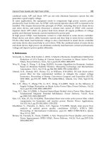
Fig. 1.2 Vehicle driven by a horse: Is there a potential for improvement if the horse is used as a
driving force?
1 Introduction 5
peripheral equipment (compressors, heat exchangers, etc.), and by more effective
heat management (recuperation, heating, cooling, etc.). The author would like only
to emphasize the cosmetic nature of such achievements although they can be
essential for a specific industrial process.
Hence, let us define the absence of ‘‘potential for development’’ in such a
meaning as is explained in Fig. 1.2. From the current point of view, will anybody
regard the horse-drawn car as a device possessing any ‘‘potential for development
(to drive faster, effectively, etc.)’’ even if it is furnished with the most modern
equipment? For example, will anybody seriously consider the fact of mounting the
cruise or electronic stability control in this car as an action toward the substantial
development if the horse remains to be the driving force?
References
1. P. Rylander, Catalytic hydrogenation in organic synthesis (Academic Press, New York,
1979)
2. N.N. Lebedev, Chemistry and technology of basic organic and petrochemical synthesis (in
Russian) (Moscow, Khimija, 1981)
3. S.B. Jaffe, Kinetics of heat release in petroleum hydrogenation. Ind. Eng. Chem. Process.
Des. Dev. 13(1), 34–39 (1974)
4. D.W. Rogers, Heats of hydrogenation (World Scientific, New Jersey, 2006)
5. E.V.W Gritz, in Handbook of Heterogeneous Catalysis, ed. by G. Ertl, H. Knözinger,
J. Weitkamp. Fat Hydrogenation, vol. 5 (Wiley-VCH, Weinheim, 1997), pp. 2224–2227
6. G. Darsow, G.M. Petruck, H.J. Alpers, European Patent Method for the preparation of
aliphatic alpha, omega-diols, 0,72,1928, 1996
7. C.H. Bartholomew, R.J. Farrauto, Fundamentals of industrial catalytic processes (Wiley,
New Jersey, 2006)
8. B. Jager, Development of commercial Fischer Tropsch reactors, in AIChE 2003 Annual
Meeting Conference Proceedings (AIChE, New Orleans, 2003), http://www.fischer-tropsch.
org/primary_documents/presentations/AIChE%202003%20Spring%20National%20Meeting/
BJager-DvlpFTReactor.pdf
9. V.I. Anikeev, A. Yermakova, B.L. Moroz, in The state of studies of the Fischer-Tropsch srocess
in Russia, AIChE 2003 Spring National Meeting (New Orleans, 2003) http://www.fischer-
tropsch.org/primary_documents/presentations/AIChE%202003%20Spring%20National%20
Meeting/Presentation%2080c%20Russia.pdf
10. T. Kabe, A. Ishihara, W. Quian, Hydrodesulfurization and Hydrodenitrogenation (Wiley-
VCH, Weinheim, 1999)
11. A.G. Bridge, in Handbook of Petroleum Refining Processes, ed. by R.A. Meyers. Hydrogen
Processing (McGraw-Hill, New York, 1996), pp. 14.1–14.68
12. P.R. Robinson, G.E. Dolbear, in Practical Advances in Petroleum Processing, ed. by C.S.
Hsu, P.R. Robinson. Hydrotreating and Hydrocracking: Fundamentals, vol. 1 (Springer,
New York, 2006), pp. 177–218
13. J. Wildschut, F.H. Mahfud, R.H. Venderbosch, H.J. Heeres, Hydrotreatment of fast pyrolysis
oil using heterogeneous noble-metal catalysts. Ind. Eng. Chem. Res. 48(23), 10324–10334
(2009)
6 1 Introduction
Chapter 2
Technological Reasons for the Selection
of Fixed-Bed Reactors
The choice for an appropriate reactor for carrying out a multiphase reaction on a
solid catalyst is always a rather challenging task. Not going deeply into the
particularities inherent in a specific process, let us point out three main problems
that should be solved in all multiphase reactions mentioned in Table 1.1
regardless of their chemical nature.
The first problem is a request for sufficient mass transfer of all reacting
compounds to the catalyst surface, especially if an active catalyst is employed. The
second point is a demand on the removal of heat generated in the course of the
reaction, and the third problem is associated with striving for the full utilization of
the catalyst potential.
At first look, the reactors with a suspended catalyst are more favorable for
multiphase reactions.
Actually, due to violent stirring, it is easy to arrange the necessary intensity of
gas–liquid and liquid–solid mass transfer and to provide the heat removal by
installation of a heat exchanger inside the slurry reactor or outside it (e.g. in
combination with an external liquid loop).
Fine catalyst particles nearly always allow one to utilize the whole bulk volume
of a single catalyst particle so that the internal surface becomes completely
accessible for reactants (no concentration gradients), which ensures a high reaction
rate.
However, slurry reactors are reluctantly applied in the industry, especially in
the medium- and large-scale production because of two paramount problems.
The first is caused by the necessity to separate a catalyst from a product. Even if
relatively big particles are initially charged into the reactor, they—being subjected
to intensive stirring—get less and less in the course of the process. Finely
powdered particles always worsen the ability of any filter to perform the filtration
by blocking the filtering surface or passing through the filter texture. Multistage
filtration is often needed to exclude catalyst penetration into the product.
Moreover, if sticky, high-molecular compounds are formed, the filtration becomes
L. B. Datsevich, Conventional Three-Phase Fixed-Bed Technologies,
SpringerBriefs in Applied Sciences and Technology,
DOI: 10.1007/978-1-4614-4836-5_2, Ó The Author(s) 2012
7
by far more dramatic by virtue of a gluing filter cake so that a frequent replacement
of filters is needed.
The second problem is related to the abrasive properties of many commercial
catalysts. Due to the attrition of stirrers, tubes, valves, control devices, etc., much
time is demanded for the revision and replacement of apparatuses, which results in
a rise in operating costs.
If a slurry reactor should operate in continuous mode, more difficulties should
be solved additionally. For example, they encompass the catalyst preparation
(e.g. activation), continuous charge, discharge and deactivation of a pyrophoric
catalyst, replacement or regeneration of a filter, and so on.
It is not surprising that continuous slurry reactors are very seldom encountered
in industrial applications if a comparatively large output is needed.
The only method that makes it possible to evade the problems attributed to a
suspended catalyst is the fixation of catalyst pellets inside a reactor (column or
tube). In such fixed-bed reactors, the conventional way to achieve the appropriate
Table 2.1 Slurry reactors versus conventional fixed-bed reactors
N Compared features Slurry reactor Fixed-bed
reactors
1 Reaction performance
1.1 Overall reaction rate related to the catalyst
mass
High Low
1.2 Overall reaction rate related to the reactor
volume (or volume of all apparatuses)
Low High
1.3 Pressure Low/Medium Medium/
High
2 Safety
2.1 Temperature control Simple Simple
2.2 Probability of runaways in exothermic
reactions
Low Extremely
high
2.3 Special measures against possible runaways
in exothermic reactions
Not necessary Nearly
always
necessary
3 Economic efficiency
3.1 Operating costs High Low
3.2 Investment costs High (at continuous
operation)
Low
3.3 Operation mode Discontinuous (continuous
operation is very seldom)
Continuous
3.4 Number of apparatuses in the continuous
operation
A lot A few
3.5 Filtration stage Necessary Absent
3.6 Demand on production flour area/working
space
Great Low
3.7 Multi-product operation in the case of
medium scale output
More cost based Less cost
based
3.8 Catalyst consumption High Low
8 2 Technological Reasons for the Selection of Fixed-Bed Reactors
mass transfer and simultaneously to remove reaction heat is the passage of a
reacting gas through the catalyst bed. Since the chemical consumption of the
reacting gas is much less than the amount of the gas which should go through the
reactor, the unreacted part of the gas is mixed with a fresh portion and returned
back to the reactor by means of the gas recirculation. Such reactors with gas loop
gain widespread acceptance in different industries.
Unfortunately, it is impossible to utilize the whole catalyst potential in indus-
trial processes since small catalyst particles cannot be used in fixed-bed reactors.
Actually, it is impracticable to apply particles less than 1 mm in size because of
the pressure drop problem (Sect. 5.2). Despite the fact that fixed-bed reactors
employ catalysts of 1–10 mm, which inevitably leads to the existence of
intraparticle diffusion limitations, the fixed-bed technology considerably exceeds
the efficiency of the slurry technique with regard to many practical features (see
Table 2.1). For instance, it is impossible to imagine any refinery hydrotreating
process of throughput about 100 m
3
of oil per h carried out in a slurry reactor.
2 Technological Reasons for the Selection of Fixed-Bed Reactors 9
Chapter 3
Traditional Approaches to the Design
of Fixed-Bed Reactors
For the purpose of the successful analysis of existing technologies, we will try to
reproduce the main arguments that were likely made by the previous generations
of process developers. On the one hand, it is interesting to retrace why the original
ideas have established such a rigid paradigm that is widely shared by the industrial
and scientific communities and, by force of habit, remains without any critical
view up to now. On the other hand, it becomes clear why the process layouts in
many applications look so uniform even when it is not demanded by the physical
or chemical nature [e.g., purification processes, including ultra-deep hydrodesul-
furization (see Chap. 6)].
The typical reaction scheme in multiphase processes can be expressed as
A þnB ! Product ðliquid or gasÞð3:1Þ
where A means an initial liquid compound to be converted, for instance, nitro-
benzene, B is a reacting gas (e.g., hydrogen), Product represents one or more
liquid or gas products, e.g., aniline and water, and n is the stoichiometric coeffi-
cient, which is equal, for example, to three in the case of complete nitrobenzene
hydrogenation to aniline.
Since the reactions between hydrogen and some organic species, which are
liquid or residing inside the liquid phase, represent the majority of industrial gas–
liquid–solid processes, in the following consideration, we will purposefully focus
on them.
It is worth pointing out that hydrogenation according to Eq. (3.1) makes no
differences toward many other industrial reactions, all of which have a great
number of common features including low gas solubility, high reaction heat,
similar process embodiments, and so on.
L. B. Datsevich, Conventional Three-Phase Fixed-Bed Technologies,
SpringerBriefs in Applied Sciences and Technology,
DOI: 10.1007/978-1-4614-4836-5_3, Ó The Author(s) 2012
11
3.1 Approaches from the Point of View of Kinetics
It is traditionally assumed that the porous structure of an individual catalyst
particle is completely occupied with liquid due to strong capillary effects (e.g. [1]).
It is also supposed that the reactor design should ensure the possibly even liquid
and gas distribution in any cross section, so that all particles in the radial direction
of an industrial reactor have uniform concentrations of reacting compounds on the
catalyst surface as well as the same temperature. (Note: In MTRs, there can be
observed a gradient of temperature and concentration in the radial direction, which
should be taken into consideration at the scaling-up and analysis of process safety.)
The reaction rate r
V
related to the volume of a single catalyst pellet, which is
situated somewhere in the catalyst bed, can be determined by a function including
such parameters as catalyst size d
cat
, temperature T and concentrations of gas and
liquid compounds on the liquid–solid interface (C
B;s
and C
A;s
) and can be written as
r
V
¼ fðd
cat
; T; C
B;s
; C
A;s
Þð3:2Þ
(Note: Eq. (3.2) represents the simplest case when there is no dependence of the
reaction rate on the concentrations of a final product(s), intermediate species, by-
products, and a solvent).
The dependence of the reaction rate on a catalyst particle size is usually
interpreted with the help of the Thiele/Zeldovich model [2, 3] in terms of the
effectiveness factor g as
r
V
¼ gr
true
ð3:3Þ
where r
true
represents the maximal reaction rate, which a catalyst particle would
demonstrate if there were no concentration gradients inside. For the simple
kinetics, as, for example, given by equation
r
true
¼ k
V
C
B;cat
ð3:4Þ
The effectiveness factor for a spherical particle with homogeneous properties can
be expressed through the so-called Thiele module u
u ¼
d
cat
2
ffiffiffiffiffiffiffiffiffiffiffi
k
V
D
B;eff
s
ð3:5Þ
as
g ¼
3
u
1
tanh u
À
1
u
ð3:6Þ
(Note: In the case of the more complex kinetic relations than given by Eq. (3.4),
it may not be possible to express the effectiveness factor g analytically as given by
Eq. (3.6)).
12 3 Traditional Approaches to the Design of Fixed-Bed Reactors
As a rule, industrial chemical engineers aiming at a certain industrial
application do not carry out the detailed investigation with regard to how the pellet
size influences the reaction performance. The explanation of this lies in the
stringent boundary conditions inherent in any industrial production. On the one
hand, it is preferable to apply as small particles as possible in order to increase the
overall reaction rate. On the other hand, the smaller the catalyst particles,
the higher the pressure drop built along the catalyst bed. Thus, the choice of the
catalyst size is predetermined by the reasonable pressure drop caused by the
passage of the reacting mixture through the reactor.
The temperature is one of the most influential process parameters. It dictates the
reactor productivity, process selectivity, and catalyst lifetime. In all industrial
applications, the value of the temperature along the catalyst bed must strongly be
restricted. Its choice represents a difficult compromise between productivity,
selectivity, and a rate of the catalyst aging. From the point of view of the compact
reactor design, it is preferable to carry out the process under possibly higher
temperatures in order to have a faster reaction rate (higher reactor productivity).
However, the high temperature inevitably leads to a rise in an amount of by-
products, which worsens the product quality. Moreover, the increased temperature
accelerates the catalyst decay due to the formation of coke or sticky, high
molecular and polymer-like compounds in catalyst pores.
Another aspect of high temperature with regard to kinetics is the process safety.
Any final product in the multi-phase process according to Eq. (3.1) can always be
regarded as an intermediate substance, which can react still further. Even if the
catalyst of the best selectivity is used, under increased temperatures, any goal
product can undergo the further conversion according to reactions presented in
Table 1.1. By-reactions are accompanied by far more heat liberation, which, in
turn, provokes further reactions with still higher heat generation.
For example, hydrogenation of furfural to furfuryl alcohol as a goal product can
proceed thereafter to tetrahydrofurfuryl alcohol and still further up to hydrocar-
bons of lower molecular weight:
ð3:7Þ
In the case of the worst scenario concerning by-reactions, the heat production in
an industrial reactor can rise sharply by several times, which leads to a very strong
and quick growth in temperature and, therefore, in pressure, resulting in reactor
damage. (Note: If the reaction is carried out in the presence of an organic solvent,
the high temperature can also cause its conversion with additional heat liberation).
The concentrations of the reacting gas and liquid species C
B;s
and C
A;s
on the
external catalyst surface are also very crucial parameters. Usually, it is assumed
that the reaction runs faster at their higher concentrations although it is correct to
some extent. If these concentrations are as high as in the liquid bulk (i.e. there is no
liquid–solid mass transfer resistance), the reaction rate is expected to be also high.
O
CH
O
O
CH
2
OH
O
CH
2
OH
+
H
2
+
2H
2
3.1 Approaches from the Point of View of Kinetics 13