- Trang chủ >>
- Khoa Học Tự Nhiên >>
- Vật lý
Semiconductor nanostructures for optoelectronic applications artech
Bạn đang xem bản rút gọn của tài liệu. Xem và tải ngay bản đầy đủ của tài liệu tại đây (7.71 MB, 436 trang )
Semiconductor Nanostructures for
Optoelectronic Applications
For a listing of recent titles in the Artech House
Semiconductor Materials and Devices Library, turn to the back of this book.
Semiconductor Nanostructures for
Optoelectronic Applications
Todd Steiner
Editor
Artech House, Inc.
Boston • London
www.artechhouse.com
Library of Congress Cataloging-in-Publication Data
A catalog record of this book is available from the U.S. Library of Congress.
British Library Cataloguing in Publication Data
Semiconductor nanostructures for optoelectronic applications
—(Artech House semiconductor materials and devices library)
1. Semiconductors 2. Nanostructured materials 3. Optoelectronic devices
I. Steiner, Todd
621.3’8152
ISBN 1-58053-751-0
Cover design by Gary Ragaglia
© 2004 ARTECH HOUSE, INC.
685 Canton Street
Norwood, MA 02062
All rights reserved. Printed and bound in the United States of America. No part of this book
may be reproduced or utilized in any form or by any means, electronic or mechanical, includ-
ing photocopying, recording, or by any information storage and retrieval system, without
permission in writing from the publisher.
All terms mentioned in this book that are known to be trademarks or service marks have
been appropriately capitalized. Artech House cannot attest to the accuracy of this informa-
tion. Use of a term in this book should not be regarded as affecting the validity of any trade-
mark or service mark.
International Standard Book Number: 1-58053-751-0
10987654321
Contents
CHAPTER 1
Introduction 1
1.1 Synopsis 1
1.2 Growth 1
1.3 Optoelectronic Devices Based on Semiconductor Nanostructures 2
1.4 Materials for Semiconductor Nanostructures 2
1.5 Summary 3
CHAPTER 2
Review of Crystal, Thin-Film, and Nanostructure Growth Technologies 5
2.1 Introduction 5
2.2 Review of Thermodynamics 6
2.2.1 Chemical Reactions 7
2.2.2 Phase Diagrams 7
2.3 Bulk Crystal Growth Techniques 8
2.3.1 Czochralski Method 8
2.3.2 Bridgman Method 11
2.3.3 Float-Zone Method 13
2.3.4 Lely Growth Methods 14
2.4 Epitaxial Growth Techniques 16
2.4.1 Liquid Phase Epitaxy 16
2.4.2 Vapor Phase Epitaxy 17
2.4.3 Molecular Beam Epitaxy 20
2.4.4 Metalorganic Chemical Vapor Deposition 24
2.4.5 Atomic Layer Epitaxy 29
2.5 Thin-Film Deposition Techniques 29
2.5.1 Plasma-Enhanced Chemical Vapor Deposition 29
2.5.2 Vacuum Evaporation 31
2.5.3 Sputtering 33
2.6 Growth of Nanostructures 34
2.6.1 Properties and Requirements of Quantum Dot Devices 35
2.6.2 Growth Techniques 36
References 41
v
CHAPTER 3
Quantum Dot Infrared Photodetectors 45
3.1 Introduction 45
3.2 QD and QDIP Structure Growth and Characterization 49
3.2.1 GaAs Capped Large and Small InAs QDs 50
3.2.2 AlGaAs Capped Large InAs MQD QDIP Structures 57
3.2.3 In
x
Ga
1-x
As Capped Small and Large InAs MQD-Based QDIP
Structures 64
3.3 QDIP Device Characteristics 76
3.3.1 Device Structures 76
3.3.2 Unintentionally Doped Large (PIG) InAs/GaAs MQD-Based
Detectors 77
3.3.3 QDIPs with AlGaAs Blocking Layers 87
3.3.4 InAs/InGaAs/GaAs QDIPs 92
3.3.5 Dual-Color QDIPs 102
3.4 Prognosis 107
Acknowledgments 109
References 109
CHAPTER 4
Quantum Dot Lasers: Theoretical Overview 113
4.1 Introduction: Dimensionality and Laser Performance 113
4.2 Advantages of an Idealized QD Laser 115
4.3 Progress in Fabricating QD Lasers 115
4.4 State-of-the-Art Complications 116
4.4.1 Nonuniformity of QDs 117
4.4.2 Parasitic Recombination Outside QDs 126
4.4.3 Violation of Local Neutrality in QDs 129
4.4.4 Excited States 131
4.4.5 Spatial Discreteness of Active Elements: Hole Burning 132
4.4.6 Intrinsic Nonlinearity of the Light-Current Characteristic 134
4.4.7 Critical Sensitivity to Structure Parameters 139
4.4.8 Dependence of the Maximum Gain on the QD Shape 142
4.4.9 Internal Optical Loss 143
4.5 Novel Designs of QD Lasers with Improved Threshold and Power
Characteristics 148
4.5.1 Temperature-Insensitive Threshold 148
4.5.2 Enhanced Power Performance 150
4.6 Other Perspectives 151
References 153
vi Contents
CHAPTER 5
High-Speed Quantum Dot Lasers 159
5.1 Introduction 159
5.2 MBE Growth of Self-Organized QDs and Their Electronic
Properties 160
5.2.1 Self-Organized Growth of In(Ga)As QDs 160
5.2.2 Electronic Spectra of In(Ga)As/GaAs QDs 161
5.3 Separate Confinement Heterostructure QD Lasers and Their
Limitations 163
5.3.1 Carrier Relaxation and Phonon Bottleneck in
Self-Organized QDs 164
5.3.2 Hot Carrier Effects in SCH QD Lasers 167
5.4 Tunnel Injection of Carriers in QDs 168
5.4.1 Tunneling-Injection Laser Heterostructure Design and
MBE Growth 169
5.4.2 Measurement of Phonon-Assisted Tunneling Times 170
5.5 Characteristics of High-Speed Tunneling-Injection QD Lasers 172
5.5.1 Room Temperature DC Characteristics 172
5.5.2 Temperature-Dependent DC Characteristics 172
5.5.3 High-Speed Modulation Characteristics 174
5.6 Conclusion 183
Acknowledgments 183
References 183
CHAPTER 6
Zinc Oxide-Based Nanostructures 187
6.1 Introduction 187
6.1.1 General Properties of ZnO 187
6.1.2 ZnO One-Dimensional Nanostructures 189
6.2 Growth Techniques 191
6.2.1 Growth Mechanisms 191
6.2.2 Growth Techniques 194
6.2.3 Summary 210
6.3 Characterizations 211
6.3.1 Structural Characterizations 211
6.3.2 Optical Characterizations 215
6.4 Device Applications 219
6.4.1 Optical Devices 219
6.4.2 Electronic Devices 221
References 224
Contents vii
CHAPTER 7
Antimony-Based Materials for Electro-Optics 229
7.1 Introduction 229
7.1.1 Antimony 229
7.1.2 Sb-Based III-V Semiconductor Alloys 230
7.1.3 Bulk Single-Crystal Growth 232
7.1.4 Applications 232
7.2 III-Sb Binary Compounds: GaSb, AlSb, and InSb 235
7.2.1 GaSb 235
7.2.2 AlSb 239
7.2.3 InSb 242
7.3 InAsSb 250
7.3.1 Physical Properties 250
7.3.2 Growth of InAsSb 253
7.3.3 Characterizations 253
7.3.4 Device Measurement 256
7.4 InTlSb 259
7.4.1 MOCVD Growth of InTlSb 259
7.4.2 InTlSb Photodetectors 262
7.5 InBiSb 262
7.5.1 MOCVD Growth of InSbBi 262
7.5.2 InSbBi Photodetectors 265
7.6 InTlAsSb 266
7.7 InAsSb/InAsSbP for IR Lasers 267
7.7.1 Growth and Characterization of InAsSb and InAsSbP 268
7.7.2 Strained-Layer Superlattices 269
7.7.3 Device Results 271
7.8 GaSb/InAs Type II Superlattice for IR Photodetectors 273
7.8.1 Introduction 273
7.8.2 Experimental Results for Type II Photodetectors 275
Acknowledgments 284
References 285
CHAPTER 8
Growth, Structures, and Optical Properties of III-Nitride Quantum Dots 289
8.1 Introduction 289
8.2 Growth of III-Nitride QDs 291
8.2.1 MBE Growth of III-Nitride QDs 292
8.2.2 Other Techniques 314
8.3 Optical Properties of III-Nitride QDs 317
8.3.1 Effects of Quantum Confinement, Strain, and Polarization 318
viii Contents
8.3.2 GaN QDs 323
8.3.3 InGaN QDs 337
8.4 Summary 343
References 344
CHAPTER 9
Self-Assembled Germanium Nano-Islands on Silicon and
Potential Applications 349
9.1 Introduction 349
9.2 Heteroepitaxy Mechanisms 349
9.3 Uniform Ge Islands 350
9.4 Registration and Regimentation of Ge Islands 355
9.5 Novel Device Applications 362
9.5.1 Optoelectronics 362
9.5.2 Thermoelectricity 365
9.5.3 Electronics Applications 366
9.5.4 Quantum Information Applications 366
9.6 Conclusion 367
References 367
CHAPTER 10
Carbon Nanotube Engineering and Physics 371
10.1 Introduction 371
10.2 Controlled Fabrication of Uniform Nanotubes in a Highly
Ordered Array 373
10.3 Interfacing with Biomolecules and Cells 379
10.4 Intrinsic Quantum Electromechanical Couplings 382
10.5 Extrinsic Coupling to Radiation Fields 391
10.6 Heterojunction Nanotubes 392
10.7 Prospects for Future Advances 396
Acknowledgments 398
References 398
Acronyms 403
About the Editor 407
Index 409
Contents ix
.
CHAPTER 1
Introduction
Todd Steiner, Air Force Office of Scientific Research
1.1 Synopsis
As we begin the twenty-first century, nanoscience and technology are advancing at a
rapid pace and making revolutionary contributions in many fields including elec
-
tronics, materials science, chemistry, biology, structures and mechanics, and optoe
-
lectronics. Although nanoscience and technology are progressing along many
fronts, the most impressive progress has been made in the area of semiconductor
technology. This book reviews recent progress in semiconductor nanostructure
growth and materials development and also reviews progress in semiconductor
devices using nanostructures, with a particular emphasis on 3D nanostructures that
have emerged during the last 10 years.
1.2 Growth
Semiconductor nanostructures have been enabled by the advancements in epitaxial
growth techniques, which are now capable of growing epilayers as thin as one
atomic layer and with interface roughnesses that are a mere fraction of a monolayer.
The development of advanced crystal and thin-film growth technologies capable of
realizing high crystalline quality and purity of materials is an enabling step in bring
-
ing semiconductor devices to reality. These growth techniques are reviewed in
Chapter 2. Chapter 2 starts with an overview of the bulk crystal growth techniques
that are required for obtaining high-quality substrates, then looks at the primary
means for producing high-quality epilayers, including liquid phase epitaxy, vapor
phase epitaxy, molecular beam epitaxy, metalorganic chemical vapor deposition
(MOCVD), and atomic layer epitaxy (ALE), as well as techniques for thin-film
deposition including plasma-enhanced chemical vapor deposition, electron cyclo
-
tron resonance, vacuum evaporation, and sputtering. Chapter 2 then discusses the
different growth modes of low-dimensional structures such as quantum wires and
quantum dots.
1
1.3 Optoelectronic Devices Based on Semiconductor Nanostructures
Since the successful development of quantum well lasers in the 1970s, one of the
richest areas of application of semiconductor nanostructures has been in the area of
optoelectronic devices, with the two most important areas being semiconductor
lasers and detectors. Early efforts focused on band-to-band transitions and have
progressed more recently to intersubband devices. In addition, the early devices util
-
ized 2D nanostructures, either superlattices or quantum wells. In recent years, the
growth of quantum dots and their integration into working devices has revolution
-
ized semiconductor devices. This book highlights results in semiconductor devices
based on quantum dots (QDs).
In Chapter 3, we review progress on quantum dot infrared detectors (QDIPs) by
providing a comprehensive discussion of the growth, structural and optical charac
-
terization, and device figures of merit. We discuss the QD and the QDIP structure
growth, QD size distribution, and the tailoring of the QD electronic energy levels
and wave functions via manipulation of the QD confinement potential. We also
show how to take advantage of stress manipulation to realize multiple-color QDIPs.
One section focuses on the QDIP device characteristics (dark current, responsivity,
noise, photoconductive gain, detectivity) for each of three classes of QDIPs dis-
cussed: InAs/GaAs/AlGaAs, InAs/InGaAs/GaAs, and dual-color InAs/InGaAs/GaAs
QDIPs.
In Chapter 4, we provide a theoretical overview of QD lasers, including the
advantages of QD lasers over quantum well lasers, the recent progress in fabricating
QD lasers, and a theoretical treatment of many issues of practical importance in
developing QD lasers, such as the nonuniformity of QDs, parasitic recombination
outside of QDs, threshold and power characteristics, and nonlinear properties. The
chapter also includes novel designs for QD lasers with improved threshold and
power characteristics.
In Chapter 5, we provide an overview of InGaAs tunnel injection QD lasers,
which have demonstrated the lowest thresholds for QD lasers and the highest modu
-
lation bandwidths. This chapter describes the growth of these QD lasers, the unique
carrier dynamics observed in self-organized QDs, their effect on high-frequency per
-
formance of QD lasers, and the novel injection technique whereby electrons are
injected into the QD ground state by tunneling. The enhanced performance of these
tunnel injection QD lasers is also described and discussed.
1.4 Materials for Semiconductor Nanostructures
Progress in semiconductor nanostructures is advancing to a wide variety of material
systems. In this book we highlight the progress in five important material systems of
technological importance. Each of these material systems has demonstrated 2D and
3D nanostructures and has had varying degrees of success in the fabrication of
optoelectronic devices.
In Chapter 6 we review progress in zinc oxide-based nanostructures, including
the Zno/ZnMgO system. Zinc oxide is emerging as an important material for
2 Introduction
ultraviolet and visible optoelectronic applications, due to the ease with which light
emission can be obtained. In Chapter 7 we review progress in antimony-based
nanostructures, including the binary compounds GaSb, InSb, and AlSb; the tertiary
compounds InAsSb, InAsP, InTlSb, and InSbBi; and the quaternary compounds
InTlAsSb and InAsSbP. Devices based on these materials are also discussed. In
Chapter 8 we review recent advances in the growth of III-nitride quantum dots and
their unique properties. The growth techniques and the structural and optical prop
-
erties associated with quantum confinement, strain, and polarization in GaN and
In
x
Ga
1–x
N quantum dots are discussed in detail.
In Chapter 9 we review the progress of nanostructures in the silicon/germanium
material system, which has the potential for bringing optoelectronics and photonics
to silicon. Specifically, we review issues of Ge island formation on Si. We show uni
-
form Ge island formation on planar Si and ordered island formation on prepat
-
terned mesa structures. We discuss the effect of growth conditions such as growth
temperature, deposition rate, deposition coverage, and substrate patterning on the
formation of the islands. We discuss the potential applications of Ge islands in the
fields of optoelectronics, thermoelectricity, electronics, and quantum information.
In Chapter 10, we present a review of carbon nanotubes, especially for optoelec
-
tronics applications. The field of carbon nanotubes has advanced quickly and
widely on many fronts during the past decade. Controlled fabrication of carbon
nanotubes of uniform diameter, length, and spacing is now feasible. Real and per-
ceived potential applications in electronics, sensing, molecular biology, actuation,
composite material, and energy storage have been demonstrated. We introduce
some of these advances and some of the fundamental properties of the carbon nano-
tubes, discuss the underlying physics of new effects and phenomena observed or
anticipated, and describe the controllable fabrication processes of new forms of
nanotubes, as well as some interesting and relatively new and unconventional direc-
tions of potential applications.
1.5 Summary
As we enter the twenty-first century, semiconductor nanostructures are revolution
-
izing many areas of electronics, optoelectronics, and photonics. We present in this
volume some of the more interesting results that are leading the revolution in the
area of optoelectronics. It is in this area that the real benefits of 3D structures are
being realized for practical devices. These achievements will serve to enhance the
contributions of semiconductor nanostructures in other areas, helping to maintain
the leading position of semiconductor nanotechnology in the more general world of
nanoscience and technology.
1.5 Summary 3
.
CHAPTER 2
Review of Crystal, Thin-Film, and
Nanostructure Growth Technologies
Alireza Yasan and Manijeh Razeghi, Northwestern University
2.1 Introduction
During the latter half of the twentieth century, in an effort to increase integration,
enhance functionality, and reduce energy consumption, the major focus of the
development of semiconductor devices was on miniaturization. As a result, semi
-
conductor devices have evolved from millimeter-sized devices capable of manipulat
-
ing electricity (e.g., transistors) into micrometer-sized devices that can handle both
electricity and light (e.g., light-emitting diodes). As we enter the twenty-first cen-
tury, we envision nanometer-sized semiconductor devices that can directly interact
with individual atoms and molecules at the nanometer level (e.g., quantum sensors).
In this regard, the development of advanced crystal and thin-film synthesis tech-
nologies capable of realizing high crystalline quality and purity of materials is an
enabling step toward making such semiconductor devices a reality.
We begin this chapter by giving an overview of thermodynamics. Chemical
reactions and phase diagrams are the subject of this first section, after which we
move on to a discussion of crystal growth techniques.
The earliest crystal growth techniques consisted of growing semiconductor
crystals in bulk form using one of the bulk crystal growth techniques: Czochralski,
Bridgman, or float zone. These methods are appropriate for the synthesis of large-
volume semiconductor crystals under thermodynamic equilibrium conditions, but
offer nearly no flexibility in terms of alloy composition or the heterostructures
needed for advanced semiconductor devices. Nevertheless, these are excellent tech
-
niques for manufacturing high-purity, near perfect, single-crystal wafers to be used
as substrates for epitaxial growth.
Epitaxial growth techniques have been specifically developed to enable the
growth of high-quality semiconductor alloys under controlled conditions. Using
these techniques, single-crystal semiconductor thin films are synthesized on a sub
-
strate. As the need for even more complex semiconductor devices increased, several
techniques have been successively developed and refined to satisfy these ever-
evolving needs. Liquid phase epitaxy is the oldest epitaxial growth technique.
Although still used in some instances, this technique is losing momentum because of
5
its poor thickness uniformity and control and poor interface. The second tech
-
nique, vapor phase epitaxy, has enjoyed broader success, but the material gener
-
ally suffers from surface defects. It is nevertheless gaining interest in the case of
GaN-based semiconductors. Two other techniques, molecular beam epitaxy and
metalorganic chemical vapor deposition, are the most widely used techniques and
have demonstrated unsurpassed capabilities in the epitaxial growth of numerous
semiconductor structures, in terms of material quality, process control, and
reliability.
Other thin-film deposition techniques exist that are primarily used for the depo
-
sition of dielectric films, but can also be used for the deposition of semiconductors in
a polycrystalline form. These techniques include plasma-enhanced chemical vapor
deposition, electron cyclotron resonance, vacuum evaporation, and sputtering.
They are much simpler and cheaper than the epitaxial growth techniques, but are
not as flexible and do not yield material that is as high in quality. Nevertheless, they
are well suited for the deposition of the dielectric films commonly employed in the
manufacturing process used for semiconductor devices.
Finally, we conclude by discussing low-dimensional structures such as quantum
wires and quantum dots. Different growth modes and possible growth techniques
are presented. The requirements for room-temperature operation of devices based
on nanostructures are briefly discussed.
2.2 Review of Thermodynamics
In this section we briefly review the thermodynamics of materials. Thermodynamics
tells us whether or not a reaction is possible. It can also determine, to some extent,
the feasibility of a chemical reaction. To get such information the free-energy func-
tion, G, is often used:
G=H−TS (2.1)
where H is the enthalpy, S is the entropy, and T is the absolute temperature. Let’s
assume that the initial state of the system (i) changes to a final state (f) due to a
chemical reaction while the temperature is kept constant. The free-energy change
can be written as
∆∆∆GG G HTS
fi
=−= −
(2.2)
The second law of thermodynamics states that “in all energy exchanges, if no
energy enters or leaves the system, the potential energy of the state will always be less
than that of the initial state (∆G<0).” This implies that systems tend to minimize
the free energy to a lower value than the initial value. After the system has achieved
the equilibrium, ∆G = 0. For a process that cannot occur, ∆G > 0. Therefore, the
possibility of occurrence of a particular reaction can be determined through the sign
of ∆G.
6 Review of Crystal, Thin-Film, and Nanostructure Growth Technologies
2.2.1 Chemical Reactions
For a typical chemical reaction involving materials X, Y, and Z in equilibrium with
x, y, and z as the stoichiometric coefficients,
xX yY zZ+→
(2.3)
The free-energy change of the reaction is given by
∆GzG xG yG
ZXY
=− −
(2.4)
Free energy of individual reactants is often written as
GGRTa
ii i
=+
0
ln
(2.5)
where G
i
0
is the free energy of the species in its standard state and a
i
is a term called
activity that reflects the change in free energy when the material is not in its standard
state. The standard state is typically 1 atmosphere partial pressure for a gas at 25°C.
A pure liquid or solid is the standard state of the relevant substance. Table 2.1 lists
the standard values of enthalpy and entropy for various substances [1]. Substitution
of (2.5) into (2.4) and letting ∆G = 0 yields
−=∆GRTK
0
ln
(2.6)
where
()
() ()
K
a
aa
Zeq
z
Xeq
x
Yeq
y
=
(2.7)
2.2.2 Phase Diagrams
Phase diagrams are the primary visualization tools in materials science because they
allow one to predict and interpret changes in the composition of a material from
2.2 Review of Thermodynamics 7
Table 2.1 Standard Values of Enthalpy and Entropy for Various Species
Species State ∆H
f
(kJ/mol) S (J/mol⋅K)
CO
2
Gas –393.51 ± 0.13 213.785 ± 0.010
Cl
2
Gas 0 223.081 ± 0.010
H Gas 217.998 ± 0.006 114.717 ± 0.002
H
+
Aqueous 0 0
H
2
O Liquid –285.830 ± 0.040 69.95 ± 0.03
H
2
O Gas –241.826 ± 0.040 188.835 ± 0.010
N Gas 472.68 ± 0.40 153.301 ± 0.003
NH
3
Gas –45.94 ± 0.35 192.77 ± 0.05
O
2
Gas 0 205.152 ± 0.005
phase to phase. As a result, phase diagrams have been proven to provide an immense
understanding of how a material forms microstructures within itself, leading to an
understanding of its chemical and physical properties. However, in some instances
materials have failed to perform to their proposed potential. One can deduce, by
referring to a material’s phase diagram, what may have happened to the material
when it was made to cause failure. In these instances, one can use thermodynamic
relations to go into the phase diagrams and extrapolate the data.
A few simple rules are associated with phase diagrams with the most important
of them being the Gibb’s phase rule . The phase rule describes the possible number of
degrees of freedom in a (closed) system at equilibrium, in terms of the number of
separate phases and the number of chemical constituents in the system. It can be sim
-
ply written as follows:
fCP=−+2
(2.8)
where C is the number of components, P is the number of phases, and f is the number
of degrees of freedom in the system. The number of degrees of freedom (f)isthe
number of independent intensive variables (i.e., those that are independent of the
quantity of material present) that need to be specified in value to fully determine the
state of the system. Typical such variables might be temperature, pressure, or con-
centration. This rule states that for a two-component, one-phase system, there are
two degrees of freedom. For example, on a P-T diagram, pressure and temperature
can be chosen independently. On the other hand, for a two-phase system, there is
only one degree of freedom and there is only one pressure possible for each tempera-
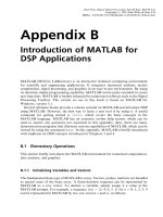
ture. Finally, for a three-phase system, there exists only one point with fixed pressure
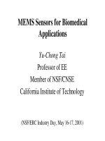
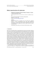
and temperature (Figure 2.1). As a real-world example, the P-T-x phase diagram of
the Ga-N system at a fixed pressure of 1 atm is shown in Figure 2.2 [2].
2.3 Bulk Crystal Growth Techniques
The historical starting point for virtually all semiconductor devices has been in the
synthesis of single crystals. Today, three major methods have been developed to
realize large-volume semiconductor crystals under thermodynamic equilibrium con
-
ditions: the Czochralski, Bridgman, and float-zone methods, which are discussed in
the following subsections.
2.3.1 Czochralski Method
The Czochralski (CZ) crystal growth method was developed in 1916 by accident.
Jan Czochralski, an engineer at the AEG Company in Berlin at that time, acciden
-
tally dipped his pen into a crucible containing molten tin and withdrew it quickly.
He observed a thin wire of solidified metal hanging at the tip. This small observation
later led to development of the Czochralski method for obtaining single crystals [3].
The Czochralski method is by far the most popular crystal growth method,
8 Review of Crystal, Thin-Film, and Nanostructure Growth Technologies
2.3 Bulk Crystal Growth Techniques 9
Gas
Liquid + gas
Liquid + GaN
GaN + Gas
Ga + GaN
Ga-N diagram at 1 atm of Nitrogen
T, K
2,500
2,000
1,500
1,000
500
Ga
20 40 60 80
N
Atomic % Nitrogen
Figure 2.2 Calculated P-T-x phase diagram for Ga-N at atmospheric pressure.
Solid
(P=1,f=2)
Liquid
(P=1,f=2)
Gas
(P=1,f=2)
Solid + gas
(P=2,f=1)
Liquid + solid
(P=2,f=1)
Gas + liquid
(P=2,f=1)
Solid + gas + liquid
(P=3,f=0)
Temperature
Pressure
Figure 2.1 P-T diagram of a one-component system showing degrees of freedom for a different
number of phases.
accounting for between 80% and 90% of all silicon crystals grown for the semicon
-
ductor industry.
The Czochralski method uses a high-purity quartz (SiO
2
) crucible filled with
pieces of polycrystalline material, called charge, which are heated above their melt
-
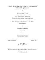
ing point (e.g., 1,415°C for silicon). The crucible, shown in Figure 2.3, is heated
either by induction using radio-frequency (RF) energy or by thermal resistance
methods. A “seed” crystal, about 0.5 cm in diameter and 10 cm long, with the
desired orientation is lowered into molten crystal, termed melt, and then drawn up
at a carefully controlled rate. When the procedure is properly done, the material in
the melt will make a transition into a solid phase crystal at the solid/liquid interface,
so the newly created material accurately replicates the crystal structure of the seed
crystal. The resulting single crystal is called the boule. Modern boules of silicon can
reach diameters of more 300 mm and be up to 2m long.
During the entire growth period, the crucible rotates in one direction at 12 to 14
rotations per minute (rpm), while the seed holder rotates in the opposite direction at
6 to 8 rpm while being pulled up slowly. This constant stirring prevents the forma
-
tion of local hot or cold regions. The crystal diameter is monitored by an optical
pyrometer that is focused at the interface between the edge of the crystal and the
melt. An automatic diameter control system maintains the correct crystal diameter
through a feedback loop control. Argon is often used as the ambient gas during this
10 Review of Crystal, Thin-Film, and Nanostructure Growth Technologies
Quartz tube
Pulling rod
Encapsulant
Heater coil
Crucible
Crucible holder
Seed crystal
Melt
Figure 2.3 Cross section of a furnace used for the growth of single-crystal semiconductor boules
by the Czochralski process.
crystal-pulling process. By carefully controlling the pull rate, the temperature of the
crucible, and the rotation speed of both the crucible and the rod holding the seed,
precise control over the diameter of the crystal is obtained.
During the Czochralski growth process, several impurities are incorporated into
the crystal. Because the crucibles are made from fused silica (SiO
2
) and the growth
process takes place at temperatures around 1,500°C, small amounts of oxygen will
be incorporated into the boule. For extremely low concentrations of oxygen impuri
-
ties, the boule can be grown under magnetic confinement. In this situation, a large
magnetic field is directed perpendicularly to the pull direction and used to create a
Lorentz force. This force will change the motion of the ionized impurities in the melt
in such a manner as to keep them away from the solid/liquid interface and therefore
decrease the impurity concentration. Using this arrangement, the oxygen impurity
concentration can be reduced from about 20 parts per million (ppm) to as low
as 2 ppm.
It is also common to introduce dopant atoms into the melt in order to tailor the
electrical properties of the final crystal: the carrier type and concentration. Simply
weighing the melt and introducing a proportional amount of impurity atoms is all
that is theoretically required to control the carrier concentration. However, impuri
-
ties tend to segregate at the solid/liquid interface, rather than be uniformly distrib-
uted inside the melt. This will in turn affect the amount of dopant incorporated into
the growing solid.
The growth of GaAs with the Czochralski method is far more difficult than for
silicon because of the vast differences in vapor pressure of the constituents at the
growth temperature of ~1,250°C: 0.0001 atm for gallium and 10,000 atm for arse-
nic. The liquid encapsulated Czochralski (LEC) method utilizes a tightly fitting disk
and sealant around the melt chamber (see the encapsulant in Figure 2.3) to prevent
the out-diffusion of arsenic from the melt. The most commonly used sealant is boric
oxide (B
2
O
3
). Additionally, pyrolytic boron nitride (pBN) crucibles are used instead
of quartz (silicon oxide) in order to avoid silicon doping of the GaAs boule. Once
the charge is molten, the seed crystal can be lowered through the boric oxide until it
contacts the charge, at which point it may be pulled.
Because the thermal conductivity of GaAs is about one-third that of silicon, the
GaAs boule is not able to dissipate the latent heat of fusion as readily as silicon. Fur
-
thermore, the shear stress required to generate a dislocation in GaAs at the melting
point is about one-fourth that in silicon. Consequently, the poorer thermal and
mechanical properties allow GaAs boules to be only about 8 inches in diameter [4]
and they contain many orders of magnitude larger defect densities than are realized
in silicon.
2.3.2 Bridgman Method
The Bridgman crystal growth method is similar to the Czochralski method except
that all of the semiconductor material (melt, seed, crystal) is kept completely
inside the crucible during the entire heating and cooling processes, as shown in
Figure 2.4.
2.3 Bulk Crystal Growth Techniques 11
A quartz crucible filled with polycrystalline material is pulled horizontally
through a furnace tube. As the crucible is drawn slowly from the heated region into a
colder region, the seed crystal induces single-crystal growth. The shape of the result-
ing crystal is determined by the shape of the crucible. As a variation to this proce-
dure, the heater may move instead of the crucible. As an alternative, the heater may
move instead of the crucible.
A couple of disadvantages are associated with the Bridgman growth method.
They result from the fact that the material is constantly in contact with the crucible.
First, the crucible wall introduces stresses in the solidifying semiconductor. These
stresses will result in deviations from the perfect crystal structure. Also, at the high
temperatures required for bulk crystal growth, silicon tends to adhere to the
crucible.
In the case of compound semiconductors, the process is slightly different from
that for silicon. The solid gallium and arsenic components are loaded onto a fused
silica ampule, which is then sealed. The arsenic in the chamber provides the over
-
pressure necessary to maintain stoichiometry. A tube furnace is then slowly pulled
past the charge. The temperature of the furnace is set to melt the charge when it is
completely inside. As the furnace is pulled past the ampule, the molten GaAs charger
in the bottom of the ampule recrystallizes. A seed crystal may be mounted so as to
contact the melt.
Typical compound semiconductor boules grown by the Bridgman method have
diameters of 2 inches. The growth of larger crystals requires very accurate control of
the stoichiometry and the radial and axial temperature gradients. Dislocation densi
-
ties of lower than 10
3
cm
–2
, compared to 10
4
cm
–2
for boules grown by the CZ
method, are routinely achieved with the Bridgman method. This method produces
the best results for compound semiconductor growth such as GaAs, and approxi
-
mately 75% of the compound semiconductor boules are grown by the Bridgman
growth method.
12 Review of Crystal, Thin-Film, and Nanostructure Growth Technologies
Furnace tube
Pull
Seed
Crucible
Molten semiconductor
Heater coils
PolycrystalCrystal
Pull
Crystal
Pull
Molten area
(a) (b)
Figure 2.4 The Bridgman growth method in a crucible: (a) solidification from one end of the
melt and (b) melting and solidification in a moving heated zone.
2.3.3 Float-Zone Method
Unlike the previous two methods, the float-zone (FZ) technique proceeds directly
from a rod of polycrystalline material obtained from the purification process as
shown in Figure 2.5. Moreover, this method does not make use of a crucible. For
this reason, extremely high-purity silicon boules, with carrier concentrations lower
than 10
11
cm
–3
, have been grown by the FZ method. But in general, this method is
not used for compound semiconductor growth.
The principle of the FZ method is as follows. A rod of an appropriate diameter
is held at the top of the growth furnace and placed in the crystal-growing chamber.
A single-crystal seed is clamped in contact at the other end of the rod. The rod and
the seed are enclosed in a vacuum chamber or inert atmosphere, and an inductive-
heating coil is placed around the rod outside the chamber. The coil melts a small
length of the rod, starting with part of the single seed crystal. A “float zone” of melt
is formed between the seed crystal and the polysilicon rod. The molten zone is
slowly moved up along the length of the rotating rod by moving the coil upward.
High-purity crystals can be obtained with FZ method.
The molten region that solidifies first remains in contact with the seed crystal
and assumes the same crystal structure as the seed. As the molten region is moved
along the length of the rod, the polycrystalline rod melts and then solidifies along its
2.3 Bulk Crystal Growth Techniques 13
Polycrystalline
rod
Seed crystal
Quartz tube
Upward
moving
heater coil
Molten zone
Single crystal
Inert gas
Figure 2.5 Cross section of the FZ crystal growth furnace.