- Trang chủ >>
- Khoa Học Tự Nhiên >>
- Vật lý
fabrication of nanomaterials using porous alumina templates
Bạn đang xem bản rút gọn của tài liệu. Xem và tải ngay bản đầy đủ của tài liệu tại đây (373.78 KB, 14 trang )
Journal of Nanoparticle Research 5: 17–30, 2003.
© 2003 Kluwer Academic Publishers. Printed in the Netherlands.
Fabrication of nanomaterials using porous alumina templates
Shoso Shingubara
Graduate School of Advanced Sciences of Matters, Hiroshima University, Kagamiyama 1-3-1,
Higashi-Hiroshima 739-8530 Japan (Fax: +81-824-24-7645; E-mail: )
Received 6 January 2003; accepted in revised form 29 March 2003
Key words: porous alumina, anodic oxidation, quantum dot, nanorod, photoluminescence, magnetic storage
Abstract
Nanofabrication by self-organization methods has attracted much attention owing to the fact that it enables
mass production without the use of expensive lithographical tools, such as an electron beam exposure system.
Porous alumina can be fabricated electrochemically through anodic oxidation of aluminum by means of such
a self-organization method, yielding highly ordered arrays of nanoholes several hundreds down to several tens
of nanometers in size. This paper is an overview of recent research on porous alumina science and technology,
nanohole array self-organization conditions and mechanisms, various methods of nanostructure formation using
porous alumina templates, optical and magnetic nanofabrication, perspectives on electronic nano device fabrication
and chemical/biological sensors and membranes.
Introduction
Porous alumina films formed by anodic oxidation of
aluminum have been intensively studied for use as
molds to form nanostructured materials. While the
technology of porous alumina and its usage as an anodic
oxide coating in tools has a long history, basic research
on self-organization of nanostructures via porous alu-
mina templates began much more recently, namely in
the mid-1990s. There is a great demand for the use
of highly ordered nanohole arrays, which can be pro-
duced on a scale of several tens of nanometers through
self-organization, in a diversity of applications, such as
high density storage media, functional nanomaterials
exhibiting quantum size effect, highly sensitive chem-
ical sensors, nano electronic devices and functional
bio-chemical membranes. This paper reviews recent
research activity on nanofabrication by porous alumina
templates; it focuses on self-organization conditions
and mechanisms, nanostructure formation, optical and
magnetic nanomaterials fabrication, electronic nano
devices and chemical and biological sensors.
Nanohole array formation and self-organization
Anodic oxide coating for aluminum and aluminum
alloys containing various acidic electrolytes has been
explored since the early 1900s, and widely used as
tableware, kettle, car body and other commodities. In
the early days of porous alumina research, Keller et al.
(1953) reported details on cell structure and anodic
voltage dependence of the cell size. They defined a cell
as the unit area containing a single nanohole. Anodi-
cally oxidized alumina film consists of nanoholes that
grow normal to the surface. Later, several authors
discussed the mechanism of nanohole formation by
electrical field assisted dissolution (Hoar & Mott,
1959; O’Sullivan & Wood, 1970; Thompson et al.,
1978). Thompson et al. discussed the effect of two
processes: (i) growth of aluminum oxide at the inter-
face between aluminum and alumina due to transport
of Al
3+
,OH
−
and O
2−
ions within the alumina film
and (ii) the dissolution and deposition of aluminum
oxide at the interface between the alumina film and
solution.
18
An explosion of porous alumina research was ignited
once the capability of producing a nanohole array
with excellent regularity was established. Masuda and
Fukuda (1995) reported that a highly ordered nanohole
array could be obtained by two-step anodization of
high purity aluminum using a 0.3 M oxalic acid solu-
tion under a constant voltage of 40 V at 0
◦
C. The
first anodization is carried out for 160 h. Although cell
arrangement at the surface is not so regular, nanohole
regularity improves with increasing film thickness.
Excellent regularity can be achieved at the hole bottom
after a long anodization period. Then the first anodic
alumina film is selectively wet etched away by the so-
called P-C etch established by Schwartz and Platter
(1975), in which a mixture of 35 ml/l 85% H
3
PO
4
and
20 g/l CrO
3
at 80
◦
C is used. The post-etched aluminum
surface has a periodic surface roughness, as evidenced
by a highly regular array of nanohole bottoms. Con-
sequently, the nanohole array formed by the second
anodic oxidation exhibits excellent regularity as a result
of the initial surface.
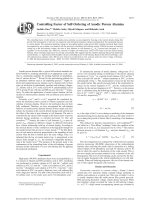
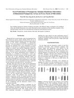
Figure 1 shows a typical nanohole array formed by
the two-step anodization. A plan view SEM micro-
graph (Figure 1a) shows a trigonal lattice of nanoholes
having an average diameter of 36 nm. The nanoholes
are slightly enlarged by wet chemical etching with
diluted phosphoric acid; the distance between holes is
90 nm. A cross-sectional view of alumina nanoholes
formed by the second, 30 s long anodization is shown
in Figure 1b. The hole depth is 220 nm; the hole bottom
is closed by a so-called barrier film 30 nm in thickness.
Neighboring nanoholes are separated by a 50 nm thick
alumina sidewall.
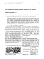
The size and geometrical arrangement of the
well-ordered nanohole array is constrained by the
self-organization condition that is determined by
the acid species. Shingubara et al. quantified the reg-
ularity of the nanohole array, in the case of oxalic acid
electrolyte, as a function of anodic voltage and acid
concentration (Shingubara et al., 1997). The regularity
of the nanohole array is the highest around 40 V; it
improves with increasing first anodization time and
acid concentration. The average cell and hole diam-
eters as a function of anodic voltage are shown in
Figure 2. The relationship between cell diameter and
voltage is almost linear, however, the cell size drops
rapidly below 20 V. Self-organization conditions in the
case of sulfuric acid (Masuda et al., 1997a) and phos-
phoric acid (Masuda et al., 1998) were investigated.
The anodic voltage that gives a well-ordered nanohole
array is found to be dependent on the acid species.
Figure 1. SEM micrographs of alumina nanohole array formed
by two step anodic oxidation of 40 V using 0.15 M oxalic acid.
(a) plan-view, (b) cross-sectional view (Shingubara et al., 1997).
Figure 2. Voltage dependence of nanohole diameter and cell
diameter, formed by oxalic anodic oxidation (Shingubara et al.,
1997).
19
Table 1. Nanohole diameter and cell diameter obtained by
typical self-organization conditions using different acid species
Acid/voltage Hole diameter (nm) Cell diameter (nm)
H
2
SO
4
/25–27 V >13 50–60
(COOH)
2
/40 V >25 90
H
3
PO
4
/195 V >200 500
Typical dimensions of the nanohole array under self-
organization conditions are summarized inTable 1. The
cell diameter under self-organization conditions are
500, 90 and 50–60 nm for phosphoric acid (anodiza-
tion voltage V
a
= 195 V), oxalic acid (V
a
= 40 V) and
sulfuric acid (V
a
= 25–27 V), respectively. Hole diam-
eters immediately after anodic oxidation are listed in
the table; additional diluted phosphorous acid etching
can increase these values, i.e., widen the holes. Cell
size differs slightly for different acids at a given anodic
voltage. For instance, the cell size formed by sulfuric
acid is slightly smaller than that formed by oxalic acid
when anodic voltage is between 30 and 40 V.
The mechanisms for nanohole self-organization
have not yet been satisfactorily identified. Jessensky
et al. (1998a,b) discussed the morphology and
formation conditions of ordered hexagonal pore arrays
for both oxalic and sulfuric acid. They suggested that
the voltage dependence of the volume expansion of the
aluminum during oxidation and the current efficiency
for oxide formation are responsible for the voltage
dependence of nanohole self-organization. Nielsch
et al. (2002a) proposed that self-ordering requires a
porosity of 10%, independent of the specific anodiza-
tion conditions. They propose that self-ordering of
porous alumina is possible with any interpore dis-
tance if the applied voltage and the pH value of the
electrolyte match the 10% porosity rule. The effect of
the stress at the aluminum/porous alumina interface
would be an essential part of these volume expan-
sion arguments. We need to further clarify the origin
of the nearest neighbor interaction between adjacent
nanoholes, since it would produce a close-packed
hexagonal lattice in two dimensions.
A new approach to controlling nanohole arrange-
ment by pretexturing the initial aluminum surface was
proposed by Masuda et al. (Masuda et al., 1997b;
Asoh et al., 2001). They prepared periodic concave
regions on the aluminum surface by pressing it using
a SiC mold with an array of periodic convex surfaces.
Figure 3 schematizes the pretexturing process. The
SiC mold was fabricated by conventional lithography
Figure 3. A method to imprint periodic concaves on Al by SiC
mold to control nanohole initial position (Asoh et al., 2001).
and dry etching. A long-range-ordered channel array
with dimensions on the order of millimeters could be
obtained by this method. This method is very effective
for fabricating a photonic band crystal that will be men-
tioned later. The density and hence the fineness of the
nanohole array is limited by the electron beam lithog-
raphy and dry etching of the SiC mold. Even through
state-of-the-art electron beam lithography technology,
a cell size finer than 50 nm would be too difficult to
fabricate in large area. Alternative pretexturing tech-
nique using atomic force microscopy (AFM) nano-
indentation was proposed (Shingubara et al., 2002a;
2003). A schema of AFM nano-indentation is shown
in Figure 4. By using a diamond-tipped AFM, peri-
odic concave regions can be formed with the desired
20
pitch and geometrical arrangement. Shingubara et al.
tried to form a tetragonal array of nanoholes using an
aluminum thin film sputtered on a Si substrate, since a
tetragonal array tends to rearrange into a trigonal array
as the holes deepen. An indenting strength of around
4 × 10
−5
N was sufficient to control the initiation of
nanohole formation by nano-indentation. The effect of
indentation interval on the regularity of nanoholes at a
fixed anodic voltage of 40 V is shown in Figure 5. At a
55 nm interval (Figure 5a), nanoholes were connected
to each other, and at a 110 nm interval (Figure 5d), addi-
tional holes formed at random between the holes whose
positions were controlled by indentation. Ordered
arrays of nanoholes were formed at 65 and 80 nm inter-
vals. Thus, controllability of nanoholes depends on
both anodic voltage and indentation interval.
Figure 4. AFM nanoindentation.
Nanofabrication using a
porous alumina template
Self-organized porous alumina nanohole arrays have
been used to fabricate a variety of nanomaterials. These
methods are categorized as follows: etching semicon-
ductor substrate using a porous alumina film as a mask,
pattern transfer using porous alumina as a template,
deposition of functional materials in the form of porous
alumina nanohole arrays by electroplating and sol–
gel, and deposition of functional materials by chemical
vapor deposition (CVD).
Porous alumina as an etching mask
Pattern transfer of nanoholes to a semiconductor sub-
strate is promising for applications such as photonic
band materials, field emitter arrays and quantum dot
arrays. In the beginning, a thin porous alumina film was
used as a dry etching mask, by placing it in contact with
the substrate (Nakao et al., 1999; Liang et al., 2002;
Chen et al., 2001). The porous alumina film was delam-
inated from the aluminum plate by a negative voltage
pulse or dissolution of aluminum by dipping in HgCl
2
solution. After removal of the nanohole bottom bar-
rier layer by Ar plasma etching or ion beam etching, a
porous alumina film is placed on the substrate. Highly
directional ion beam etching is necessary for substrate
etching since the alumina nanohole aspect ratio (the
ratio of depth to diameter) is very high. GaAs and InP
substrates by reactive ion beam etching (RIBE) (Nakao
et al., 1999; Liang et al., 2002), and an InGaN/GaN
Figure 5. Plan-view SEM micrographs of porous alumina film surfaces that were formed by AFM nano-indentation followed by anodic
oxidation at 40 V using 0.15 M oxalic acid for 5 min. Indentation force was 4.16 × 10
−5
N. Indentation interval d
int
was varied from 55 to
110 nm. (Shingubara et al., 2002).
21
multiple quantum well (MQW) (Chen et al., 2001)
were assessed. The alumina mask showed high toler-
ance to RIBE using a Br
2
/N
2
mixed gas system. In
this method, maintaining the gap between the porous
alumina and the substrate at a minimum is essential
for achieving ultrahigh uniformity. Recently, an alter-
native method, namely using a porous alumina film
deposited directly on the semiconductor substrate, was
proposed (Shingubara et al., 2001). A thin porous alu-
mina film with an aspect ratio below 5 was formed
on a Si/SiO
2
substrate by the use of sputtered alu-
minum. Reactive ion etching using chlorine with a
high self-bias of RF plasma proved effective for pat-
tern transfer to Si. There was a significant reduction
in hole size due to redeposition of nonvolatile mate-
rials on the sidewall of nanoholes. For instance, the
initial porous alumina hole size of 45 nm was reduced
to 13 nm Si holes when a higher aspect ratio of porous
alumina nanoholes mask was used. The problem with
this method is the non-uniformity of the porous alu-
mina mask thickness, which would require a specially
designed anodic oxidation electrode to improve.
Pattern transfer by replica of
porous alumina film
Pattern transfer of alumina nanohole arrays to metallic
hole arrays using a replica was proposed (Masuda &
Fukuda, 1995). After detachment of the porous alu-
mina film by wet dissolution of the aluminum substrate
using HgCl, the bottom barrier layer was removed by
ion beam etching. Then, the negative of the nanohole
array pattern was transferred to PMMA by coating it on
the porous alumina film. Finally, the porous aluminum
film was chemically wet-etched, leaving behind only
the resist pattern. The PMMA pattern can be used to
form a replica by deposition of metals via sputtering,
evaporation, etc.
Electroplating or sol–gel synthesis on
porous alumina
Numerous studies have been conducted on filling of
conductive materials in porous alumina nanoholes by
electroplating. Possible applications include coloring
of the aluminum plate itself (Asada, 1969; Gphausen &
Schoener, 1984) and magnetic recording media for a
high-density magnetic disk (Kawai & Ishiguro, 1975;
1976). Prior to electroplating, the bottom barrier layer
should be thinned to less than about 10 nm. Wet
chemical etching of the anodic alumina film using
a diluted phosphorous acid solution (pore widening
treatment), or step-wise lowering of the anodic volt-
age down to 10 V were employed. Alternating current
(AC) or pulsed-current electroplating was used since
the impedance of the barrier layer at the nanohole
bottom is too large to afford for direct current (DC)
electroplating. Research activity on the electroplating
of magnetic materials in porous alumina has intensified
remarkably in recent years; details will be presented
later. As for other metals, nanowire array formation of
gold (Shingubara et al., 1997) and silver (Sauer et al.,
2002) have been reported.
Sol–gel provides an alternative synthesis route for
nanomaterial fillings in porous alumina nanoholes.
Monodisperse hollow nanocylinders containing crys-
talline titania particles have been filled by an aqueous
solution of titanium tetrafluoride (Imai et al., 1999).
Hollow nanotubes comprising In
2
O
3
and Ga
2
O
3
were
synthesized by sol–gel chemistry (Cheng & Samulski,
2001) and sol–gel synthesis of an array of C-70 sin-
gle crystal nanowires in a porous alumina template was
investigated (Cao et al., 2001a,b).
CVD deposition on porous alumina
Chemical vapor deposition of materials in porous
alumina nanoholes is a challenging topic for CVD
researchers. Since porous alumina can contain
extremely high aspect ratio holes, it is of great inter-
est to discover how high aspect ratio of holes can be
filled by CVD. Working in a supercritical fluid medium
is one way of obtaining excellent deposition profiles.
Palladium films were synthesized at controlled depths
within porous alumina disks by hydrogen reduction of
organopalladium compounds dissolved in supercritical
CO
2
at 60
◦
C (Fernandes et al., 2001). Guided by a sim-
ple mass transport model, Pd films ranging from 2 to
80 µm in thickness were deposited at prescribed depths
between 80 and 600 µm.
Carbon nanotube (CNT) CVD in porous alumina has
been intensively studied by several groups recently (Li
et al., 1999a,b; Iwasaki et al., 1999; Sung et al., 1999;
Sui et al., 2002; Hu et al., 2001; 2002; Wang et al.,
2002). It is well known that CNT–CVD needs cataly-
sis for thermal decomposition of precursors. Li et al.
(1999a,b) used electrodeposited Co as a precursor,
while Iwasaki et al. (1999) used Nb located beneath
the aluminum layer as a precursor. A SEM micro-
graph of a well-ordered array of CNT is shown in
22
Figure 6. SEM image of array of carbon nanotube fabricated in
porous alumina template (Li et al., 1999).
Figure 6. Using Co catalysis, pyrolysis of C
2
H
2
was car-
ried out at 650
◦
C. CNTs with diameters ranging from
10 to several hundred nanometers and lengths of up
to 100 µm can be produced. This structure is highly
promising for an ultrahigh-density field emitter array.
CNT formed through Co catalysis by this method has
a multi-walled structure (Hu et al., 2002). Wang X.H.
et al. (2000) reported low-temperature deposition of
CNTs at around 520
◦
C by microwave plasma ass-
isted CVD.
Functional optical nanomaterials embedded in
porous alumina
There have been many attempts to fill semiconductor
materials in porous alumina nanoholes in an effort to
produce highly luminescent materials. Although they
are still slightly too large to exhibit the quantum con-
finement effect, nanoholes have excellent luminescent
properties not found in bulk materials. We ought to
begin our discussion by considering the photolumines-
cence (PL) properties of the porous alumina nanohole
array itself. Du et al. (1999) investigated PL proper-
ties of porous alumina membranes fabricated by anodic
oxidation using oxalic acid or sulfuric acid. They found
Figure 7. Photoluminescence spectra of a porous alumina
membrane prepared inoxalic acid. (a) as prepared, (b) 200
◦
C×4h,
(c) 300
◦
C × 4 h, (d) 400
◦
C × 4 h, (e) 500
◦
C × 4 h, (f) 550
◦
C × 4h,
(i) porous Si (Du et al., 1999).
a blue PL band in the wavelength range of 400–600 nm,
with an intensity peak at 460 nm. This band origi-
nates from singly ionized oxygen vacancies (F
+
center)
in porous alumina membranes. The PL intensity of
a porous alumina film was increased by annealing at
a higher temperature as shown in Figure 7. It can
be seen that the PL intensity of the porous alumina
film fabricated using oxalic acid and annealed above
400
◦
C is stronger than that of porous silicon. The PL
intensity of porous alumina fabricated using oxalic
acid was much stronger than that fabricated using
sulfuric acid.
Enhanced PL was observed by filling titania doped
with Terbium (Tb) or Erbium (Eb) (Gaponenko et al.,
2000; 2001). An assembly of ZnO nanoparticles was
synthesized by immersing the porous alumina mem-
brane in a mixture of zinc butanol and water at 60
◦
C
and then heating at 200
◦
C (Shi et al., 2000). PL
measurements showed a peak at 485 nm. Compared
with the PL spectra of nanostructured bulk ZnO, the
PL intensity of ZnO nanoparticles in the alumina
membrane is enhanced by a factor of 20 (Figure 8).
This arises from the increase in singly ionized oxy-
gen vacancies (F-centers) in the ZnO nanoparticles
located within the pores of the alumina membrane.
A CdS nanowire array fabricated by electrodeposi-
tion exhibited three ultraviolet PL bands and one
yellow–green PL band (Wang et al., 2002). GaN
nanoparticles filled by sol–gel synthesis showed excel-
lent PL properties (Chen et al., 2001; Cheng et al.,
23
Figure 8. The PL spectra induced by the nano-ZnO particles
in the assembly (curve C), and of he nanostructured ZnO bulk
(curve D) (Shi et al., 2000).
1999). A laser dye, rhodamine 6G (RG6), and another
luminescent organic molecule, 8-hydroxyquinoline
aluminum (Alq(3)), were impregnated into porous alu-
mina nanoholes (Xu et al., 2002). A clearly blue-shifted
PL was observed for both the Alq(3) and RG6 con-
tained within the nanoholes. The measured spectral
characteristics demonstrate the influence of pore size
on the emission of the organic molecules. These studies
suggest that porous alumina films have a high poten-
tial for use in electroluminescent devices. Kukhta et al.
(2002) proposed a simple method for attaching elec-
trodes to nanomaterials embedded in nanoholes. The
bottom part of the alumina layer, placed between the
aluminum and pore space, is removed by a slow reduc-
tion in anodic voltage down to zero. The schema of
the structure, and an SEM micrograph of the nanohole
bottom after bottom opening are shown in Figure 9.
The use of a porous alumina cathode results in a less
homogeneous electric field, and hence, more intensive
auto-electron emission and higher cathode efficiency.
Luminescent organic molecules were adsorbed on the
walls of the cylindrical pores, causing a significant
increase in luminophor concentration. These organic
electroluminescent devices can easily be manufactured
and they are more efficient and stable as compared with
the usual layered structures.
Photonic band crystals have been intensively stud-
ied in order to develop nonlinear optical wave-guides.
Porous alumina membrane is one of most promising
two-dimensional (2-D) photonic crystal materials. The
pretexturing technique has been employed to fabricate
Figure 9. (a) A model of the organic electroluminescent cell, (b)
SEM micrograph of the porous alumina bottom after opening the
bottom barrier layer (Kukhta et al., 2002).
Figure 10. Transmission spectra of naturally ordered porous alu-
mina for H-polarization light. The average interval of the air holes
was 500 nm (Masuda et al., 2001).
large, single-domain alumina nanohole arrays to be
used as 2-D photonic band crystals. A common optical
grating is used to prepattern the aluminum substrate,
which is subsequently anodized under mild conditions
to yield an AOF with a photonic band gap in the vis-
ible region (Wehrspohn & Schilling, 2001; Mikulskas
et al., 2001). The 2-D photonic crystals were fabricated
using self-organized porous alumina with a high aspect
ratio of over 200. The transmission properties of the
resultant ordered air-hole array in the alumina matrix
exhibited a stop band in the spectrum that corresponded
to the band gap in 2-D photonic crystals as shown in
Figure 10 (Masuda et al., 1999; 2000).
24
Magnetic nanomaterials embedded in
porous alumina
Magnetic materials embedded in porous alumina
matrix have a long history (Kawai & Ishiguro, 1975).
The main purpose of these studies is to realize a
high-density magnetic recording media. Soon, the
recording density of a magnetic hard disk will exceed
100 Gbit/in
2
, and materials for 1 terabit/in
2
are strongly
required. A dense array of magnetic nanoparticles is
considered to be the most promising candidate (Sun
et al., 2001), however, it is difficult to obtain perpen-
dicular magnetic anisotropy by nanoparticles. Mag-
netic nano-rods or -dots embedded in porous alumina
nanoholes satisfy the requirement for perpendicular
anisotropy because magnetic rods with a high aspect
ratio (ratio of height to diameter) can easily be formed
in a porous alumina template. Ni (Nielsch et al., 2000;
2002b; Zheng et al., 2000; 2002; Metzger et al., 2001;
Kroll et al., 2001), Co (Metzger et al., 2001; Sun et al.,
2000; 2001; Kroll et al., 2001; Strijkers et al., 1999),
Fe (Metzger et al., 2001; Kroll et al., 2001; Menon
et al., 2000), and alloys such as CoFe (Menon et al.,
2001), NiCo (Zhu et al., 2001) were filled into porous
alumina by pulsed or AC electrodeposition and their
magnetic properties were determined. In most cases,
magnetic nanorods with diameters ranging from 10 to
60 nm, and nearest neighbor distances between 60 and
120 nm were fabricated by porous alumina prepared by
oxalic acid or sulfuric acid anodic oxidation. A typi-
cal cross-sectional TEM image of a nanomagnet array
is shown in Figure 11, where polycrystalline Co dots
with a diameter of 40 nm were formed (Metzger et al.,
2001). Using a porous alumina template, we can con-
trol the height of ferromagneticdots by deposition time.
Figure 12 shows M-H hysteresis loops of a Co particle
array with a height of (a) 5 nm, and (b) 60 nm. There
is a clear difference in the magnetic anisotropy; the
thinner Co rods (length = 5 nm) have a rather in-plane
anisotropy, while the thicker rods (length = 220 nm)
Figure 11. TEM cross-section ofporous alumina and Co particles
at the bottom of pores (Sun M. et al., 2001).
have an out-of-plane anisotropy. Thus, the magnetic
anisotropy of ferromagnetic rods is mainly governed
by shape. The structure of the Co rods was investigated
with nuclear magnetic resonance, which revealed that
the wires exhibit a mixture of fcc and hcp texture with
the (0001) texture of the hcp fraction oriented preferen-
tially perpendicular to the wires (Nielsch et al., 2000).
These features are common to all ferromagnetic met-
als. In the case of Fe rods, the existence of a critical
diameter for which the coercivity has a maximum was
observed at room temperature (Menon et al., 2000).
The maximum coercivity obtained at room tempera-
ture is 2640 Oe. However, there was no maximum in
coercivity as a function of diameter at 5 K. Controlla-
bility of alloy composition by electroplating is good
to the Fe
1−x
Co
x
(0 <x<1) alloy system studied
by Menon et al. (2001). The crystal structure is bcc
at the Fe end. As the Co content increases, the crys-
tal structure remains bcc until about 67% Co, above
which the structure transforms into a mixture of hcp
and fcc. For Fe
0.67
Co
0.33
nanorods with a diameter of
9 nm, the coercivity is about 2900 Oe, whereas for
Fe
0.33
–Co
0.67
nanowires, it is about 2850 Oe. Tempera-
ture and size dependence of magnetic properties show
no indication of superparamagnetic effects down to a
wire diameter of 9 nm. For a nanomagnet array density
of above 1 terabit/in
2
, a nanohole pitch below 25 nm is
required. This is currently not achievable through self-
organization of porous alumina nanohole arrays, and
would require further technological breakthrough.
Figure 12. M–H hysteresis loops of Co particle array: (a) 5 nm
long, (b) 60 nm long (Sun M. et al., 2001).
25
Nanostructure formation on solid substrate:
Toward electron devices
Several authors have discussed fabrication of
nanoscaled electron devices using porous alumina
templates. A relatively easy application is a field
emitter array (Govyadinoc & Zakhvitcevich, 1999;
Hu et al., 2001), as the technique enables the fab-
rication of ultrahigh-density emitter arrays. Carbon
nanotube arrays (Hu et al., 2002) and other metal
arrays (Govyadinoc & Zakhvitcevich, 1999) were pro-
posed. A comprehensive overview of electronic device
applications was reported by Routkevitch et al. (1996).
Fabrication of one-dimensional metal or semiconduc-
tor (CdS, CdS
x
Se
1−x
,Cd
x
Zn
1−x
S, GaAs) wires and
one-dimensional superlattices was proposed. Electron
tunneling phenomena via the nanohole bottom barrier
layer was observed for the first time (Routkevitch et al.,
1996), which showed a stepwise increase in conduc-
tance with increasing voltage in the Al/alumina bottom
barrier film/Ni wire/NiO/Ag system. The Coulomb
blockade phenomenon with a single tunneling barrier
was observed in a similar structure at low temperature
(Haruyama & Sato, 2000; Haruyama et al., 2000).
Transport property of CNT grown in porous alumina
nanoholes has been investigated by several authors.
Li et al. (1999b) grew sophisticated Y-junction CNT
arrays. The Y-junction CNTs were produced by CVD
growth catalyzed by electrodeposited Co in branched
porous alumina template. The branch was made by
a sudden decrease in the anodic voltage, which was
very efficient in the anodic oxidation for the change
in nanohole diameter as well as pitch. Transport mea-
surements showed an reproducible rectifying behavior
at room temperature (Papadopoulos et al., 2000). The
result was well explained by a junction with an abrupt
change in band gap due to the nanotube diameter,
and possibility for a new heterojunction devices were
suggested. Haruyama et al. (2001a,b,c; 2002) further
investigated low temperature conductance proper-
ties of CNTs buried in porous alumina nanoholes.
Coulomb blockade related localization effect in a
single tunnel-junction/CNT system, and anomalous
localization effects associated with excess Co catalyst
diffused in multiwalled carbon nanotubes (MWNTs)
were observed. Further they slightly diffuse atoms of
electrode materials into one end of MWNTs, grown
using nanoporous alumina membranes. Diffusion of
the light-mass materials lead to weak localization
in Altshuler–Aronov–Spivak oscillation. In contrast,
diffusion of heavy-mass materials at the volume ratio
of only about 5% change this weak localization to
antilocalization, and they proposed an electron-wave
phase switching circuit using this effect.
Kouknin et al. (2000) observed an unexpected elec-
tronic bistability in the current–voltage characteristics
of CdS-embedded porous alumina with current paths
in both the lateral and vertical directions. However, the
mechanism behind this bistable switching phenomenon
remains unclear. They also observed an extremely high
photoresistivity in CdS and ZnSe nanowires electrode-
posited onto a porous alumina film. The resistance
of these nanowires increases by one to two orders of
magnitude when exposed to infrared radiation, possi-
bly because of real-space transfer of electrons from
the nanowires into the surrounding alumina by photon
absorption (Kouklin et al., 2001).
The above-mentioned studies of electronic devices
utilize porous alumina fabricated on alumina plates.
Thus, it is difficult to apply them to devices in inte-
grated circuits. Shingubara was the first to study
porous alumina nanohole array formation on Si sub-
strates (Shingubara et al., 1999). They sputtered a thick
(20 µm) pure aluminumfilm on a SiO
2
/Si substrate, and
carried out the two-step anodic oxidation of aluminum.
By keeping the aluminum surface flat during sputtering,
a well-ordered array of nanoholes was fabricated. In
this method, the electrode makes contact with the alu-
minum film during anodic oxidation. If the SiO
2
layer
is thin enough to allow tunneling current and a heavily
doped Si substrate with low resistivity is used, elec-
trode can be made using the backside of a Si wafer. In
later years, porous alumina films were formed on con-
ductive solid substrates, such as ITO (indium tin oxide)
(Chu et al., 2002) and n-type Si without SiO
2
layer
(Crouse et al., 2000). SEM images of nanohole bottom
on ITO and Si are shown in Figure 13. The nanohole
bottom differs from those formed on aluminum; a void
is formed underneath the bottom barrier layer of alu-
mina in both cases. The SEM image of the bottom
barrier layer formed on SiO
2
is shown in Figure 14
(Shingubara et al., 2002a,b). In contrast to Figure 13,
the interface between the porous alumina barrier layer
and the SiO
2
layer is flat, and aluminum islands remain
at the interface. By further anodic oxidation, these
aluminum islands are completely oxidized and dimin-
ished since anodically formed alumina film is an ionic
conductor. The porous alumina bottom morphology
varies depending on whether the under-layer is conduc-
tive or not. The void formation underneath the bottom
barrier is thought to be caused by dissolution of alu-
mina at the interface due to the high ionic current
26
Figure 13. SEM micrographs of porous alumina nanohole bottom on (a) ITO (Chu et al., 2002), and (b) n-Si (Crouse et al., 2000).
Figure 14. Cross-sectional observation of porous alumina nanohole bottom on SiO
2
formed by 0.15 M oxalic anodization of 40 V.
(a) SEM micrograph, (b) TEM micrograph (Shingubara et al., 2002).
flowing perpendicular to the interface. An excellent
hexagonal aluminum dot array was observed on SiO
2
upon completion of the anodic oxidation of the sput-
tered aluminum film as shown in Figure 15. The dot
diameter and height are 40 and 15 nm, respectively.
The space between dots is controlled by additional
anodic oxidation time. Each dot can be used as a single
electron memory node. Characteristics of the conduc-
tion between aluminum dots was recently measured;
Coulomb blockade caused by single electron tunneling
between aluminum dots was observed at liquid He tem-
peratures (Shingubara et al., 2002c). Bandyopadhyay
(2001) proposed qubit operations for quantum com-
puters by the use of porous alumina. Universal 2-qubit
operations are possible by a gate consisting of two tri-
layered quantum dots that are electrochemically syn-
thesized within two adjacent pores in a porous alumina
film. The two outer layers are ferromagnetic metals or
semiconductors while the middle layer is a semicon-
ductor with long spin coherence time (e.g., silicon).
Figure 15. AFM image of aluminum hexagonal dot array formed
at the interface between porous alumina and SiO
2
(Shingubara
et al., 2002).
A single electron is injected into the middle semicon-
ductor layer and its spin encodes a qubit.
In silicon ultra large scale integrated circuit (ULSI)
technology, low dielectric constant materials are
27
urgently required. Porous alumina has high poten-
tial as a low dielectric constant material because its
porosity can be controlled by a pore widening treat-
ment using diluted phosphoric acid. The fundamental
idea had been proposed by IBM in the early stages
of integrated circuit (IC) development (Schwartz &
Platter, 1975). However, this aspect was reconsid-
ered recently for dielectric film applications (Lazarouk
et al., 2000a,b). A low dielectric constant of about
2.4 was attained by chemical etching of porous alu-
mina films in an anodizing solution. The intralevel
insulator based on porous alumina was found to have
the following properties: the breakdown voltage was
above 400 V and the leakage current at an applied
voltage of 15 V was below 10
−9
A/cm
−2
. A study on
thermal overheating under high current density oper-
ation has shown that the developed structure offers
advantages over aluminum interconnection passivated
by silica insulator. The developed processing tech-
nique was tested for CMOS submicron technology.
The fabricated aluminum-porous alumina structure
demonstrated good chemical and thermal stability, and
excellent adhesion to the layers above and below it.
Membranes and chemical sensors
Porous alumina films can be used as membranes
with nanopore channels of extremely narrow size
distribution. Shawaqfeh and Baltus (1999) formed a
membrane by post-oxidation processing that removed
unoxidized aluminum as well as the barrier layer of
alumina. They made bilayer composite membranes by
varying the current density during the oxidation pro-
cess. The hydraulic permeability of membranes formed
in phosphoric acid and the diffusive permeability of
membranes formed in sulfuric acid were measured.
These measured values showed excellent agreement
with predicted values determined by kinetic studies.
Another method for the preparation of nanoporous
membranes from anodically oxidized aluminum was
described by Mozalev et al. (2001). Pores of an exist-
ing free anodic alumina film were protected with
gelatin gel, and the oxide barrier layer was chemically
dissolved from the bottom of the film. The mem-
branes thus produced were examined as electrolyte
carriers/separators for Li rechargeable batteries by
impedance and cyclic charge/discharge measurements.
Repeated electrodeposition–dissolution of Li on Ni
and Al substrates in a LiPF6/propylene carbonate elec-
trolyte was performed through the alumina membrane.
Furthermore, transport behavior of monovalent and
divalent solutes across mesoporous nanopore alumina
membranes was investigated as a function of pore
diameter, pH and ionic strength (Bluhm et al., 1999).
Trace amounts of the radiotracers Cs-137, Sr-85,
Na-22 and Ca-45 were present in the feed solutions at
Figure 16. Capacitance response of moisture sensors made by porous alumina with various porosity (Basu et al., 2001).
28
concentrations ranging from 10
−9
to 10
−12
M with total
salt concentrations from 0.1 to 10
−4
M. The divalent
cations Ca
2+
and Sr
2+
exhibited lower diffusion rates
than the monovalent cations Cs
+
and Na
+
for mem-
branes with 20 nm diameter pores. This difference was
attributed to the Donnan exclusion effect due to the
positively charged alumina surface.
It is well known that the electrical properties of
porous alumina are sensitive to moisture. Thus, it can
potentially be used as a humidity sensor. Basu et al.
(2001) proposed a new type of micro-humidity sensor
based on porous alumina. They developed a moisture
sensor based on porous alumina with interdigitated
metallic electrodes for the measurement of moisture
concentration in the 50–100 ppm range. Figure 16
shows the capacitor response of the interdigitated sen-
sors. There is an almost linear relationship between
moisture concentration and capacitance. The sensors
have good sensitivity and are highly reproducible.
Concluding remarks
Porous alumina template has a high potential for use
in a diversity of applications, including electronic
devices, magnetic storage disks, sensors, and biologi-
cal membranes. However, there are some problems that
need urgent attention: (1) the pitch of a highly ordered
nanohole array formed by self-organization is still lim-
ited, (2) a method to control nanohole diameters below
5 nm for observing the quantum confinement effect
has yet to be devised and (3) a fabrication procedure
for integrating porous alumina nanohole membranes
on semiconductor solid substrates, while at the same
time maintaining their mechanical stability, has not yet
been established. The full potential of porous alumina
in nano-sciences and technologies can only be realized
through persistent efforts at solving these problems.
References
Asada T., 1969. Japanese Patent. No. 824505.
Asoh H., K. Nishio, M. Nakao, A. Yokoo, T. Tamamura &
H. Masuda, 2001. Fabrication of ideally ordered anodic porous
alumina with 63 nm hole periodicity using sulfuric acid. J. Vac.
Sci. Technol. B19, 569.
Bandyopadhyay S., 2001. A nanospintronic universal quantum
gate. Physica E 11, 126.
Basu S., S. Chatterjee, M. Saha, S. Bandyopadhyay,
K.K. Mistry & K. Sengupta, 2001. Study of electrical char-
acteristics of porous alumina sensors for detection of low
moisture in gases. Sensors and Actuators, B-Chemical 79, 182.
Bluhm E.A., E. Bauer, R.M. Chamberlin, K.D. Abney,
J.S. Young & G.D. Jarvinen, 1999. Surface effects on cation
transport across porous alumina membranes. Langmuir 15,
8668.
Cao H.Q., Y. Xu, J.M. Hong, H.B. Liu, G. Yin, B.L. Li, C.Y.
Tie & Z. Xu, 2001a. Sol–gel template synthesis of an array of
single crystal CdS nanowires on a porous alumina template.
Adv. Mater. 13, 1393.
Cao H.Q., Z. Xu, X.W. Wei, X. Ma & Z.L. Xue, 2001b. Sol–
gel synthesis of an array of C-70 single crystal nanowires in a
porous alumina template. Chem. Commun. 6, 541.
Chen L., A.J. Yin, J.S. Im, A.V. Nurmikko, J.M. Xu & J. Han,
2001. Fabrication of 50–100 nm patterned InGaN blue light
emitting heterostructures. Physica Status Solidi A 188, 135.
Cheng G.S., L.D. Zhang, X.G. Zhu, S.H. Chen, Y. Li, Y. Zhu &
G.T. Fei, 1999.Synthesis of orderly nanostructure of crystalline
GaN nanoparticles on anodic porous alumina membrane.
Nanostruct. Mater. 11, 421.
Cheng B. & E.T. Samulski, 2001. Fabrication and characteriza-
tion of nanotubular semiconductor oxides In
2
O
3
and Ga
2
O
3
.
J. Mater. Chem. 11, 2901.
Chu S.Z., K. Wada, S. Inoue & S. Todoroki, 2002. Formation
and microstructures of anodic alumina films from aluminum
sputtered on glass substrate. J. Electrochem. Soc. 149, B321.
Crouse D., Y H. Lo, A.E. Miller & M. Crouse, 2000. Self-
ordered pore structure of anodized alumina on silicon and
pattern transfer. Appl. Phys. Lett. 76, 49.
Du Y., W.L. Cai,C.M. Mo, J. Chen,L.D. Zhang &X.G. Zhu, 1999.
Preparation and photoluminescence of alumina membranes
with ordered pore arrays. Appl. Phys. Lett. 74, 2951.
Fernandes N.E., S.M. Fisher, J.C. Poshusta, D.G. Vlachos,
M. Tsapatsis & J. J. Watkins, 2001. Reactive depositionof metal
thin films within porous supports from supercritical fluids.
Chem. Mater. 13, 2023.
Gaponenko N.V., J.A. Davidson, B. Hamilton, P. Skeldon,
G.E. Thompson, X. Zhou & J.C. Pivin, 2000. Strongly
enhanced Tb luminescence from titania zerogel solids meso-
scopically confined in porous anodic alumina. Appl. Phys. Lett.
76, 1006.
Gaponenko N.V., O.V. Sergeeve, E.A. Stepanova, V.M. Parkun,
A.V. Mudryi, H. Gnaser, J. Misiew, L.J. Balk &
G.E. Thompson, 2001. Optical and structural characterization
of erbium-doped TiO
2
xerogel films processe on porous anodic
alumina. J. Electrochem. Soc. 148, H13.
Govyadinoc A.N. & S.A. Zakhvitcevich, 1999. Field emitter
arrays based on natural self-organized porous anodic alumina.
J. Vac. Sci. Technol. B16, 1222.
Gphausen H.J. & G.C. Schoener, 1984. Plating and Surf.
Finishing 71, 56.
Haruyama J. & Y. Sato, 2000, Influence of phase fluctuation in
external environment on coulomb blockade an array system
of single tunnel junctions/Ni nanowires. Appl. Phys. Lett. 76,
1698.
Haruyama J., K. Hijioka, M. Tako & Y. Sato, 2000. Coulomb
blockade related to mutual coulomb interaction in an external
environment in an array of single tunnel junctions connected
to Ni nanowires. Phys. Rev. B. 62, 8420.
Haruyama J., I. Takesue, S. Kato, K. Takazawa & Y. Sato, 2001a.
Mesoscopic phenomena in nano-porous alumina films: single
29
nano-tunnel junctions connected to Ni-nanowires and carbon
nanotubes. Appl. Surf. Sci. 175–176, 597.
Haruyama J., I. Takesue, T. Hasegawa & Y. Sato, 2001b. Coulomb
blockade related to a localization effect in a single tunnel-
junction/carbon-nanotube system. Phys. Rev. B 63, 073406.
Haruyama J., I. Takesue & T. Hasegawa, 2001c. Drastic change of
phase interference by small diffusion of heavy-mass electrode
atoms in carbon nanotubes and phase switching device. Appl.
Phys. Lett. 79, 269.
Haruyama J., I. Takesue & T. Hasegawa, 2002. Anomalous local-
ization effects associated with excess volume of cobalt catalyst
in multiwalled nanotubes. Appl. Phys. Lett. 81, 3031.
Hoar T.P. & N.F. Mott, 1959. A mechanism for the formation of
porous anodic oxide films on aluminium. J. Phys. Chem Solids
9, 97.
Hu W.C., L.M. Yuan, Z. Chen, D.W. Gong & K. Saito, 2002.
Fabrication and characterization of vertically aligned car-
bon nanotubes on silicon substrates using porous alumina
nanotemplate. J. Nanosci. Nanotechnol. 2, 203.
Hu W., D. Gong, Z. Chen, C.A. Grimes & P. Kichambare, 2001.
Growth of well-aligned carbon naotube arrays on silicon sub-
strates using porous alumina film as a nanotemplate. Appl.
Phys. Lett. 79, 3083.
Imai H., Y. Takei, K. Shimizu, M. Matsuda & H. Hirashima, 1999.
Direct preparation of anatase TiO
2
nanotube in porous alumina
membranes. J. Mater. Chem. 9, 2971.
Iwasaki T., Y. Motoi & T. Den, 1999. Multiwalled carbon nan-
otubes growth in anodic alumina nanoholes. Appl. Phys. Lett.
75, 2044.
Jessensky O., F. Muller & U. Gosele, 1998a. Self-organized for-
mation of hexagonal pore arrays in anodic alumina. Appl. Phys.
Lett. 72, 1173.
Jessensky O., F. Muller & U. Gosele, 1998b. Self-organized
formation of hexagonal pore structures in anodic alumina. J.
Electrochem. Soc. 145, 3735.
Kawai S. & I. Ishiguro, 1975. Magnetic properties of anodic
oxide coatings on aluminum containing electrodeposited Co
and Co–Ni. J. Electrochem. Soc. 122, 32.
Kawai S. & I. Ishiguro, 1976. Recording characteristics of
anodic oxide films on aluminum containing electrodeposited
ferromagnetic metals and alloys. J. Electrochem. Soc. 123,
1047.
Keller F., M.S. Hunter & D.L. Robinson, 1953. Structural features
of oxide coatings on aluminum. J. Electrochem. Soc. 100, 411.
Kouklin N., S. Bandyopadhyay, S. Teresin, A. Varfolomeev &
D. Zaretsky, 2000. Electronic bistability in electrochemically
self-assembled quantum dots: A potential nonvolatile random
access memory. Appl. Phys. Lett. 76, 460.
Kouklin N., L. Menon, A.Z. Wong, D.W. Thompson,
J.A. Woollam, P.F. Williams & S. Bandyopadhyay, 2001.
Giant photoresistivity and optically controlled switching in
self-assembled nanowires. Appl. Phys. Lett. 79, 4423.
Kroll M., L.J. de Jongh, F. Luis, P. Paulus & G. Schmid, 2001.
Magnetization reversal and magnetic anisotropy of Fe, Ni and
Co nanowires in nanoporous alumina membranes. Mat. Res.
Soc. Symp. Proc. 674., U4.5.1.
Kukhta A.V., G.G. Gorokh, E.E. Kolesnik, A.I. Mitkovets, M.I.
Taoubi, Y.A. Koshin & A.M. Mozalev, 2002. Nanostructured
alumina as a cathode of organic light-emitting devices. Surf.
Sci. 507, 593.
Lazarouk S., S. Katsouba, A. Demianovich, V. Stanovski, S.
Voitech, V. Vysotski & V. Ponomar, 2000a. Reliability of built
in aluminum interconnection with low-epsilon dielectric based
on porous anodic alumina. Solid State Electron. 44, 815.
Lazarouk S., S. Katsouba, A. Leshok, A. Demianovich, V.
Stanovski, S. Voitech, V. Vysotski & V. Ponomar, 2000b.
Porous alumina as low-epsilon insulator for multilevel metal-
lization. Microelectron. Eng. 50, 321.
Li J., C. Papadopoulos & J.M. Xu, 1999a. Highly-ordered carbon
nanotube arrays for electronics applications. Appl. Phys. Lett.
75, 367.
Li J., C. Papadopoulos & J. Xu, 1999b. Growing Y-junction
Carbon Nanotubes. Nature 402, 253.
Liang J., H. Chik, A. Yun & J. Xu, 2002. Two-dimensional lateral
superlattices on anostructures: Nonlithographic formation by
anodic membrane template. J. Appl. Phys. 91, 2544.
Masuda H. & K. Fukuda, 1995. Ordered metal nanohole arrays
made by a two-step replication of honeycomb structures of
anodic alumina. Science 268, 1466.
Masuda H., F. Hasegawa & S. Ono, 1997. Self-ordering of cell
arrangement of anodic porous alumina formed in sulfuric acid
solution. J. Electrochem. Soc. 144, L127.
Masuda H., H. Yamada, M. Saitoh, H. Asoh, M. Nakao &
T. Tamamura, 1997. Highly ordered nanochannel-array archi-
tecture in anodic aloumina. Appl. Phys. Lett. 71, 2770.
Masuda H., K. Yada & A. Osaka, 1998. Self-ordering of cell
configuration of anodic porous aloumina with large-size pores
in phosphorous acid solution. Jpn. J. Appl. Phys. 37, L1340.
Masuda H., M. Ohya, H. Asoh, M. Nakao, M. Nohtomi &
T. Tamamura, 1999. Photonic crystal using anodic porous
alumina, Jpn. J. Appl. Phys. Part2-Lett. 38, L1403.
Masuda H., M. Ohya, H. Asoh & K. Nishio, 2001. Photonic band
gap in naturally occurring ordered anodic porous alumina. Jpn.
J. Appl. Phys. 40, L1217.
Menon L., M. Zheng, H. Zeng, S. Bandyopadhyay &
D.J. Sellmyer, 2000. Size dependence of the magnetic prop-
erties of electrochemically self-assembled Fe quantum dots.
J. Electron. Mater. 29, 510.
Menon L., S. Bandyopadhyay, Y. Liu, H. Zeng & D.J. Sellmyer,
2001. Magnetic and structural properties of electrochemically
self-assembled Fe1-xCox nanowires. J. Nanosci. Nanotechnol.
1, 149.
Metzger R.M., M. Sun, G. Zangari & M. Shamsuzzoha, 2001.
Magnetic nanoparticle array with ultra-uniform length elec-
trodeposited in highly ordered alumina nanopores (‘alumite’).
Mat. Res. Soc. Symp. Proc. 636, D.9.33.1.
Mikulskas I., S. Juodkazis, R. Tomasiunas & J. G. Dumas, 2001.
Aluminum oxide photonic crystals grown by a new hybrid
method. Adv. Mater. 13, 1574.
Mozalev A., S. Magaino & H. Imai, 2001. The formation of
nanoporous membranes from anodically oxidized aluminium
and their application to Li rechargeable batteries. Electrochim.
Acta 46, 2825.
Nakao M., S. Oku, T. Tamamura, K. Yasui & H. Masuda, 1999.
GaAs and InP nanohole arrays fabricated by reactive beam
etching using highly ordered alumina membrane. Jpn. J. Appl.
Phys. 38, 1052.
Nielsch K., F. Muller, A.P. Li & U. Gosele, 2000. Uniform nickel
deposition into ordered alumina pores by pulsed electrodepo-
sition. Adv. Mater. 12, 582.
30
Nielsch K., J. Choi, K. Schwirn, R.B. Wehrspohn & U. Gosele,
2002a. Self-ordering regimes of porous alumina: The 10%
porosity rule. Nano Lett. 2, 677.
Nielsch K., R. Hertel, R.B. Wehrspohn, J. Barthel, J. Kirschner,
U. Gosele, S.F. Fischer & H. Kronmuller, 2002b. Switching
behavior of single nanowires inside dense nickel nanowire
arrays. IEEE Trans. Magn. 38, 2571.
O’Sullivan J.P. & G.C. Wood, 1970. Nucleation and growth of
porous anodic films on aluminum. Proc. R. Soc. A317, 511.
Papadopoulos C., A. Rakitin, J. Li, A.S. Vedeneev & J.M. Xu,
2000. Electronic transport in y-junction carbon nanotubes.
Phys. Rev. Lett. 85, 3476.
Routkevitch D., A.A. Tager, J. Haruyama, D. Almawlawi,
M. Moskovits & J.M. Xu, 1996. Nonlithographic nano-wire
arrays: Fabrication, physics, and device application. IEEE
Trans. Electron Devices 43, 1646.
Sauer G., G. Brehm, S. Schneider, K. Nielsch, R.B. Wehrspohn,
J. Choi, H. Hofmeister & U. Gosele, 2002. Highly ordered
monocrystalline silver nanowire arrays. J. Appl. Phys.91, 3243.
Schwartz G.C. & V. Platter, 1975. An anodic process for form-
ing planar interconnection metallization for multilevel LSI.
J. Electrochem. Soc. 122, 1508.
Shawaqfeh A.T. & R.E. Baltus, 1999. Fabrication and char-
acterization of single layer and multi-layer anodic alumina
membrane. J. Membrane Sci. 157, 147.
Shi G., C.M. Mo, W.L. Cai & L.D. Zhang, 2000. Photolumines-
cence of ZnO nanoparticles in alumina membrane with ordered
pore arrays. Solid State Comm. 115, 253.
Shingubara S., O. Okino., H. Sakaue & T. Takahagi, 1997.
Ordered two-dimensional nanowire array formation using self-
organized nanoholes of anodically oxidized aluminum. Jpn. J.
Appl. Phys. 36, 7791.
Shingubara S., O. Okino, Y. Sayama, H. Sakaue & T. Takahagi,
1999. Two-dimensional nanowire array formation on Si sub-
strate using self-organized nanoholes of anodically oxidized
aluminum. Solid State Electron 43, 1143.
Shingubara S., O. Okino, Y. Murakami, H. Sakaue & T. Takahagi,
2001. Fabrication of nanohole array on Si using self-organized
porous alumnina mask. J. Vac. Sci. Technol. B19, 1901.
Shingubara S., Y. Murakami, K. Morimoto, H. Sakaue &
T. Takahagi, 2002a. Formation of Al nanodot array by the com-
bination of nano-indentation and anodic oxidation. Mat. Res.
Soc. Symp. Proc. 705, 133.
Shingubara S., Y. Murakami, H. Sakaue & T. Takahagi, 2002b.
Formation of Al dot hexagonal array on Si using anodic
oxidation and selective etching. Jpn. J. Appl. Phys. 41, L340.
Shingubara S., Y. Murakami, K. Morimoto, G.R. Wu &
T. Takahagi, 2002c. Aluminum nanodot array formation by
anodic oxidation and its conduction properties. Extended Abst.
2002 Solid State Devices Mater. p. 266.
Shingubara S., Y. Murakami, K. Morimoto & T. Takahagi, 2003.
Formation of aluminum dot array by combination of nanoin-
dentation and anodic oxidation of aluminium. Surface Science
(in press).
Sui Y.C., B.Z. Cui, R. Guardian, D.R. Acosta, L. Martinez &
R. Perez, 2002. Growth of carbon nanotubes and nanofibres in
porous anodic alumina film. Carbon 40, 1011.
Strijkers G.J., J.H.J. Dalderop, M.A.A. Broeksteeg,
H.J.M. Swagten, & W.J.M. de Jonge, 1999. Structure and
magnetization of arrays of electrodeposited Co wires in anodic
alumina. J. Appl. Phys. 86, 5141.
Sun S., D. Weller & C.B. Murray, 2001. In: Plumer M.L.,
Ek J.v. and Weller D. eds. The Physics of Ultra-High-Density
Magnetic Recording, Springer, New York, pp. 249–276.
Sun M., G. Zangari & R.M. Metzger, 2000. Cobalt island arrays
with in-plane anisotropy electrodeposited in highly ordered
alumite. IEEE Trans. Magn. 36, 3005.
Sun M., G. Zangari, M. Shamsuzzoha & M. Metzger, 2001. Elec-
trodeposition of highly uniform magneticnanoparticle arrays in
ordered alumite. Appl. Phys. Lett. 78, 2964.
Sung S.L., S.H. Tsai, C.H. Tseng, F.K. Chiang, X.W. Liu &
H.C. Shih, 1999. Well-aligned carbon nitride nanotubes syn-
thesized in anodic alumina by electron cyclotron resonance
chemical vapor deposition. Appl. Phys. Lett. 74, 197.
Thompson G.E., R.C. Furneaux, G.C. Wood, J.A. Richardson &
J.S. Goode, 1978.Nucleation and growth ofporous anodic films
on aluminum. Nature 272, 433.
Wang Y.H., Y. Q. Xu, W.L. Cai & J.M. Mo, 2002. New method to
prepare CdS nanowire arrays. Acta Physico-Chim. Sinica 18,
943.
Wang X.H., Z. Hu, Q. Wu & Y. Chen, 2002. Low-temperature
catalytic growth of carbon nanotubes under microwave plasma
assistance. Catalysis Today 72, 205.
Wehrspohn R.B.& J. Schilling, 2001. Electrochemicallyprepared
pore arrays for photonic-crystal applications. MRS Bull. 26,
623.
Xu C.X., Q.H. Xue, Y. Zhong, Y.P. Cui, L. Ba, B. Zhao &
N. Gu, 2002. Photoluminescent blue-shift of organic molecules
in nanometre pores. Nanotechnology 13, 47.
Zeng H., S. Michalski, R.D. Kirby, D.J. Sellmyer, L. Menon &
S. Bandyopadhyay, 2002. Effects of surface morphology on
magnetic properties of Ni nanowire arrays in self-ordered
porous alumina, J. Phys. Cond. Matter. 14, 715.
Zheng M., L. Menon, H. Zeng, Y. Liu, S. Bandyopadhyay,
R.D. Kirby & D.J. Sellmyer, 2000. Magnetic properties of
Ni nanowires in self-assembled arrays. Phys. Rev. B 62,
12282.
Zhu H., S.G. Yang, G. Ni, D.L. Yu & Y.W. Du, 2001. Fabrica-
tion and magnetic properties of Co
67
Ni
33
alloy nanowire array.
Scripta Mater. 44, 2291.