- Trang chủ >>
- Khoa Học Tự Nhiên >>
- Vật lý
influence of dopant in the synthesis, characteristics and ammonia sensing behavior
Bạn đang xem bản rút gọn của tài liệu. Xem và tải ngay bản đầy đủ của tài liệu tại đây (756.84 KB, 6 trang )
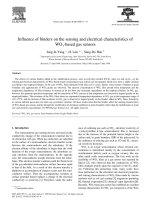
Influence of dopant in the synthesis, characteristics and ammonia sensing behavior
of processable polyaniline
Partha Pratim Sengupta, Pradip Kar, Basudam Adhikari
⁎
Materials Science Centre, Indian Institute of Technology, Kharagpur 721302, India
abstractarticle info
Article history:
Received 6 September 2007
Received in revised form 20 December 2008
Accepted 22 December 2008
Available online 11 January 2009
Keywords:
Processable polyaniline
Thin film sensor
Organic semiconductors
Ammonia sensing
Polymers
Polyaniline (PANI) was synthesized by oxidative polymerization of aniline as well as aniline hydrochloride by
ammonium persulfate in the presence of para-toluene sulfonic acid (PTSA). This helped in direct usage of the
conducting PANI solution for film casting and use as a device for ammonia gas sensing. Viscosity change with
applied shear rate was measured for both the polymers. Solid PANI powder was isolated from its tetrahydrofuran
solution by using methanol as non-solvent. Thermogravimetric analysis investigated the thermal properties of
the solid PANI salts. Elemental analysis of both PANI synthesized in presence of PTSA and PANI synthesized in
presence of HCl and PTSA was investigated. A thin coherent film of both the conducting PANI were deposited on
glass slides precoated with poly vinyl alcohol (PVA) crosslinked with maleic acid (MA) and was directly used in
the sensor device. The morphology of the deposited films was analyzed by scanning electron micrograph. The
films were further characterized by Attenuated total reflectance Fourier transformed infrared spectroscopy, ultra
violet-visible spectroscopy and X-ray diffraction analyses. Finally, both the doped PANI films on MA crosslinked
PVA coated glass slides were used to measure the conductivity and ammonia gas-sensing characteristics.
© 2009 Elsevier B.V. All rights reserved.
1. Introduction
Polyaniline (PANI) salt synthesized by chemical route is insoluble
in organic solvents. Therefore, it requires treatment with a base to
make it soluble in N-methyl-2-pyrrolidone (NMP) for film casting.
Such films are subsequently doped for obtaining better conductivity. It
would be convenient if the PANI salt could be doped in situ during its
synthesis and made soluble in a solvent for direct film casting. But the
first technique generally suffers from poor processability and lower
conductivity. Cao et al. [1] and others [2–4] reported the use of
functionalized protonic acids, which doped PANI and simultaneously
resulting doped PANI completely soluble in common organic solvents.
Palaniappan and Amarnath [5] synthesized polyaniline-dodecyl
hydrogen sulphate-acid salt by using aniline as the monomer, while
Yin and Ruckenstein [6] synthesized processable polyaniline co-doped
with dodecyl benzene sulfonic acid (DBSA) and hydrochloric acid
using aniline hydrochloride as the monomer. Many researchers mea-
sured the conductivity using pellet of PANI salt powder [6–8]. The
reported conductivity of PANI in pellet form is in the range 0.5 to 12 S/
cm. Yin and Ruckenstein [6] although claimed to have good solubility
in organic solvents and good processability of PANI doped with DBSA,
but they measured the conductivity in the pellet form. Lu and
coworkers [8] also measured the conductivity of PANI pellets doped
with DBSA and para toluene sulfonic acid (PTSA), although they
claimed their doped polymer to be soluble in organic solvents. There
are only a few reports of direct doping and casting of PANI films in the
salt form using functionalized dopants. None of the above works have
shown gas sensing performances of PANI. For getting good response
and reproducibility in gas sensing, a thin fi lm would be better than a
pellet. Because in case of film, absorption and desorption of gas would
be faster than pellet due to molecular order and compactness inside
the film.
Wu and coauthors [9] used a DBSA doped PANI thin film as an
ammonia sensor and found response and recovery time of 2 and 5 min
respectively for 100 ppm ammonia gas. They found a resistance of
150 Ω for such films. Other researchers [10,11] used a templated PANI
film as an ammonia gas sensor for different concentrations of ammo-
nia gas. These works reveal that PANI based ammonia sensors possess
a wide range of recovery and response times, which might be due to
different substrates used for film deposition, different film deposition
techniques and different film thicknesses. A useful approach for the
improvement of the processability of conducting polymers involves
blending with suitable matrix polymers such as poly (vinyl alcohol)
(PVA) [12–14]. An ammonia sensor based on conducting polypyrrole
was one of the early practical realizations of conducting polymer
based sensors. Its sensitivity, however, was relatively low and the
response was not very reversible
[15]. However, Ojio and Miyata [16]
prepared polypyrrole-poly (vinyl alcohol) (PPy-PVA) films by electro-
chemical polymerization. Linsey and Street [17] studied gas sensing
behavior of PPy-PVA films prepared by electrochemical polymeriza-
tion on to a precoated PVA matrix. These studies contrasted the
advantages of mechanical properties of the host polymer with the
electrical properties of PPy-PVA composite films.
Thin Solid Films 517 (2009) 3770–3775
⁎ Corresponding author. Tel.: +91 3222 283966; fax: +91 3222 255303.
E-mail address: (B. Adhikari).
0040-6090/$ – see front matter © 2009 Elsevier B.V. All rights reserved.
doi:10.1016/j.tsf.2008.12.049
Contents lists available at ScienceDirect
Thin Solid Films
journal homepage: www.elsevier.com/locate/tsf
We like to communicate a comparative study of structural and
electrical properties of polyaniline doped with PTSA (PANI_PTSA) and
co-doped with hydrochloric acid (HCl) and PTSA (PANI_HCl_PTSA).
Both the single and co-doped PANI were directly deposited as thin
films on maleic acid (MA) crosslinked PVA precoated glass substrate
and their ammonia gas sensing characteristics were studied. Here we
have primarily focused our investigation on the comparative study of
the extent of intermolecular force, chain association and morphology
of the single and co-doped PANI and the direct effects on their con-
ductivity and ammonia gas sensing properties.
2. Experimental details
2.1. Materials
Aniline (Merck, India) was distilled under reduced pressure prior
to use. Reagent grade aniline hydrochloride (Merck, India) and
ammonium persulfate ((NH
4
)
2
S
2
O
8
) (Merck, India), hydrochloric
acid (Merck, India), polyvinyl alcohol (Fluka AG, Germany), and
maleic acid (Loba Chemie, India) were used without further
purification. Tetrahydrofuran (THF) (Merck, India) was dried (by
using sodium metal) and used as solvent.
2.2. Synthesis of processable polyaniline
Processable P ANI_PTS A and P TS A_HCl_PTS A w ere synthesized by
chemical oxidati ve polymerization. For synthesis of PA NI_PTS A, aniline
(3.72g)andPTSA(15.18g)weredissolvedin170mlTHFinthemoleratio
of 1:2 in a round bottom flask and maintained at − 5 ° C. T o this s olutio n
ammonium persulphat e (APS) (11.42 g) dissolved in 30 ml deionized
water was added drop wise. To synthesize PANI_HCl_PTSA the
same procedure was followed as that of PA NI_PTSA using ani line
hydr ochloride (5 .18 g) instead of aniline. Two reaction mixtures were
gently stirred and polymerizations were carried out for 48 h. A green
solution of PANI salts were formed in both the cases instead of
precipitation. Since this P ANI solution is unable to form a film on a
glass surface, a MA cr osslinked PVA surface was chosen for PANI film
deposition. MA crosslinked PVA coated glass slides were immersed in
boththePANIreactionmixturesandtakenoutafter1htodepositthin
films of emer ald ine salts on the sl ides. The films deposi t ed aft er
prolonged immersion beyond 1 h wer e found to dev elop crac ks on
drying. The deposited thin films were then dried at 40 °C for 2 h and then
washed several times with metha nol and d eionized water to remov e any
unreacted APS and a niline or bypr oducts. Finally the washed films wer e
dried in v a cuum at 50 °C for 6 h. A th in unifo rm film formati on on
crosslinked PVA coated glass slide was observed which was used fo r
further study.
2.3. Precipitation of doped polyaniline from green solution
It is mentioned in the previous section that the synthesized PANI
salt solution in aqueous THF could not form a thin film on glass
surface. On the contrary, when a non-solvent such as methanol was
added to the solution fine particles of solid PANI were precipitated
slowly. For the purpose of characterization of the precipitated poly-
mer, it was filtered and washed several times with methanol and
deionized water. The solid polymer was then converted to polyaniline
base by treating with 1 M ammonia solution for 48 h. The PANI base
was washed several times with deionized water and dried under
vacuum. The dried solid PANI base was then dissolved in N-methyl-2-
pyrrolidone (NMP) and a uniform film was obtained by solution
casting. The dried film was doped with PTSA and PTSA_HCl prior to
characterization.
2.4. Physical characterizations
2.4.1. Thickness measurement for the deposited films
The thickness of the polymer film was measured by using a BAKER
(Type J130/3) dial thickness gauge. The thickness of the polymer film
was obtained by subtracting the thickness of the MA crosslinked PVA
coated glass slide without polymer film from the MA crosslinked PVA
coated glass slide with polymer film.
2.4.2. Elemental analyses
The elemental analyses of PANI_HCl_PTSA and PANI_PTSA were
done in order to investigate the level of doping in both the polymer
films. The results are shown in Table 1. Carbon, hydrogen and nitrogen
were analyzed by Perkin Elmer C H N S/O Analyzer 2400 while S and
Cl percentages were estimated by the Shöniger Flask combustion
technique [18]. The theoretical weight percentages of the elements
shown in Table 1 were calculated based on Scheme 1.
2.4.3. Viscosity shear-rate measurement
TheviscositychangewithshearrateoftheprocessablePANI_HCl_
PTSA and PANI_PTSA solutions in THF and water obtained after
polymerization was studied in Advanced Rheometer , TA Instruments
AR 1000.
2.4.4. Thermal characterizations
Thermal stability of polymer samples was analyzed by thermo-
gravimetric analysis (TGA) using Perkin Elmer Pyris Diamond ther-
mogravimetric analyzer in N
2
atmosphere from 50 °C to 600 °C at a
heating rate of 10 °C/min.
2.4.5. Scanning electron microscopy (SEM)
For the surface morphology study, the SEM images of the polymer
films deposited on the glass slides (coated with MA crosslinked PVA)
were taken in a field emission SEM instrument (VEGA TESCAN).
2.4.6. Attenuate d total reflectance Fourier transf ormed infr ared sp ectr oscopy
(ATR–FTIR)
The ATR–FTIR spectra of the doped polyaniline films deposited on
precoated glass slide were taken on a Thermo Nicolet Nexus 870
spectrophotometer between 400 and 4000 cm
− 1
.
2.4.7. X-ray diffraction (XRD) analysis
The XRD analysis of the PANI film samples deposited on the MA
crosslinked PVA coated glass slide was done in Philips Type PW 1710
using Cu K
α
(λ =1.542 A°). The XRD analysis of MA crosslinked PVA
coated glass slide was also done in the same instrument.
Table 1
Elemental analysis of the polyaniline co doped with HCl and PTSA and polyaniline doped with only PTSA.
Sample % elements S/N
ratio
Cl/
N
ratio
Dopant (mol%) σ ×10
2
(S/cm)
C H N Cl S O PTSA HCl
Exp Th Exp Th Exp Th Exp Th Exp Th Exp Th
PANI_HCl_PTSA 60.67 65.2 5.78 4.73 11.05 9.8 5.20 6.2 7.55 5.6 9.75 8.4 0.21 0.27 0.236 0.146 2.3
PANI_PTSA 62.59 64.59 4.85 4.8 8.93 7.9 ––9.26 9.06 14.37 13.6 0.45 – 0.289 – 1.4
3771P.P. Sengupta et al. / Thin Solid Films 517 (2009) 3770–3775
2.4.8. Electrical properties
A four-probe setup fabricated in our laboratory [19] was used to
measure the resistivity of the PANI films. According to four-point
probe method the resistivity (ρ) was calculated using the relation
ρ =2πSV= IðÞ
Where S is the probe spacing (mm), which was kept constant, I is the
supplied current in mA and the corresponding voltage (V)was
measured in mV. The conductivity (σ) was calculated using the rela-
tionship, σ =1/ρ.
2.5. Gas sensing
In our gas sensor set up [1 9], the ammonia–air mix ture was taken from
the headspace of a b ottle containing ammonia sol ution. The ammoni a–air
mixture was continuousl y passed to a closed gas sensing chamber ha ving
a small outlet. The ammoni a concentration in t he mixture was estimated
by trapping a known volume of ammonia–air mix ture in an ice-cold dilute
hydr ochloric acid solution that w as titrated with a standard sodium
h ydr o xid e sol ution be for e and a fter ammonia trap ping [11]. The poly ani-
line film specimen (1 cm ×1 cm) was mounted on a bakelite sheet and
then four cont acts wer e made on t h e specimen by copper wir es and silv er
paste with 2 mm distance between t he probes. A constant current sour ce
(Keithley Model 224) and a multimeter (Keithley model 196) were used to
apply the current and to measure the voltage drop respectively. R and R
0
are the r esistances m easured in t he presence of ammonia and air
respectively. A kno wn volume of ammonia gas was introduced (con-
centration calibrated t o b e at 100 ppm) and the change of resistance was
monitored at every 30 s int erval allowing the reading to stabiliz e. Aft er
some time when the r esponse (R/R
0
) became saturat ed the a mmonia gas
flo w w a s st opped and air was passed to allow the s ensor m ateri al t o
recover the original state. This span covered one cycle of gas exposure. The
sensitivity of the sensor was measured as the corresponding R/R
0
value
when the response curv e reached the highest satur at ed level (when the
curve becomes par allel to X-axis). The response time was measured as
the time between the entry of ammonia gas to the polyaniline sensor
and the saturation of its response. The recovery time is the time in be-
tween the saturation response to the initial v alue in presence of air [11].
3. Results and discussion
3.1. Synthesis of processable PANI_ PTSA and PANI_HCl_PTSA
Due to the presence of methyl group in the functionalized protonic
acid PTSA, in-situ doped PANI became soluble in organic polymeriza-
tion medium (THF). PANI synthesized by conventional methods in the
presence of aqueous hydrochloric acid [20] precipitates out due to
polarization of π-electron cloud of the growing polymer. Once the
polymer phases out from the polymerization medium, it becomes
very difficult to solvate. However, the methyl group of PTSA imparts a
non-polar interaction with the surrounding THF medium and resists
phasing out of PANI. The para-toluene sulphonate anion (PTSA
−
)
dopant is likely to decrease the conductivity of PANI. Therefore, we
opted to use both HCl and PTSA as dopant and found good processable
polymer with better conductivity than only PTSA doped PANI at the
same conditions of polymerization. MA crosslinked PVA coated glass
slide was inserted directly into the polymerization medium for
polymer deposition (both single and co-doped). The thicknesses of
both the polymer films were maintained within 0.08–0.09 mm. The
reaction schemes for both doped films are shown in Scheme 1.
3.2. Elemental analysis
PANI_PTSA contains about 0.289 mol% dopant while PANI_HCl_
PTSA contains 0.382 mol% (0.236 mol% PTSA+0.146 mol% HCl)
dopant (Table 1). The amount of dopants in PANI_HCl_PTSA was
calculated from the atomic S/N and Cl/N ratios. This shows that the
migration of HCl as a dopant is higher than that of PTSA because of the
smaller size of the Clˉ ion. Thus, co-doped PANI shows better
conductivity than that of single doped PANI. All other values for the
elements are obtained as shown in Table 1.
3.3. Viscosity-shear rate
The change of viscosity of PANI solution with shear rate is related
to the inter molecular forces between polymer chains [21] and
polymer chain length. As chain length increases the intermolecular
forces increase due to more dipole interaction or intermolecular
Scheme 1. Synthesis of polyaniline doped with PTSA (PANI_PTSA) and co-doped polyaniline with HCl and PTSA (PANI_HCl_PTSA).
3772 P.P. Sengupta et al. / Thin Solid Films 517 (2009) 3770–3775
hydrogen bonding with =N– atom. Fig. 1 describes the thixotropic
behavior of PANI_HCl_PTSA and PANI_PTSA solutions. The shear
thinning of PANI_PTSA solution starts at a lower shear rate of 2.2 s
− 1
compared to PANI_HCl_PTSA, which undergoes shear thinning at a
shear rate of 9.5 s
− 1
. The initial viscosity of PANI_HCl_PTSA is also
much higher. Both these observations comply with the fact that
PANI_HCl_PTSA has higher polymer chain length and inter-chain
forces compared to PANI_PTSA. During protonation to the amine
group of aniline a competition occurs between HCl and PTSA. The
smaller size of the Cl
−
counterion present in the PANI_HCl_PTSA
actually favors better polymer chain growth than only PTSA
−
anion
from PANI_PTSA.
3.4. Thermal studies
An initial 2–3% weight loss (Fig. 2)inbothdopedpolymerisfound
until 160 °C. This occurred due to the release of bound water molecules.
This is followed by a rap id loss in weight in the PANI_HCl_PTSA due to
the release of HCl molecules followed by a slow release of PTSA until the
500 °C (Fig. 2) when the third stage of degradation starts. In case of
PANI_PTSA only single stage degradation starts at 180 °C and at about
400 °C the weight loss is about 30% due to the dedoping of PTSA (Fig. 2).
Finally, a third stage degradation occurs for both the doped PANI due to
complete degradation and decomposition of polymer backbone.
However, for the PANI_HCl_PTSA the third stage of decomposition
starts at a much higher temperature (530 °C) and about 55% mass is
retained at 600 °C while at that temperature only 35% mass is retained in
PANI_PTSA (Fig. 2). Therefore, it can be said that PANI_HCl_PTSA is
thermally less stable than that of PANI_PTSA due to the release of HCl
molecule at low temperature. Otherwise, the co-doped PANI is more
stable than that of single doped PANI.
3.5. SEM analysis
The SEM image of co-doped PANI deposited on MA crosslinked
PVA coated glass slide shows a uniform distribution while that of
single doped PANI with PTSA shows some uneven surface morphology
(Fig. 3). This can be explained as due to steric contribution of the PTSA
dopant. The amounts of large size PTSA
−
ion is more in PANI_PTSA
than that of PANI_HCl_PTSA causing adjacent ring distortion and also
some incompatibility with MA crosslinked PVA substrate matrix.
Again, PANI_HCl_PTSA due to the presence of co-dopant small HCl
molecule with PTSA
−
, facilitates larger compactness of structure. So,
PANI_HCl_PTSA is better compatible with the matrix of MA cross-
linked PVA than PANI _PTSA.
3.6. ATR–FTIR analysis
The ATR–FTIR spectra of PANI_HCl_PTSA and PANI_PTSA are shown
in Fig. 4.TheN–H stretching, aromatic –CH
2
– stretching and –CH–
stretching were observed at 3461 cm
− 1
, 2931 cm
− 1
and 2852 cm
− 1
respectively for PANI_HCl_PTSA while for PANI_PTSA those bands were
observed at higher wave numbers (Fig. 4) showing lesser conjugation
[22]. The quinoid (1644 cm
− 1
) and benzenoid (1544 cm
− 1
) stretching
Fig. 1. The viscosity change with shear rate of the co-doped and single doped PANI
solutions obtained after polymerization reaction.
Fig. 2. Thermogravimetric analysis of co-doped and single doped PANI powder.
Fig. 3. SEM images of (a) single doped PANI_PTSA and (b) co-doped PANI_HCl_PTSA
films deposited on crosslinked PVA coated glass slide.
3773P.P. Sengupta et al. / Thin Solid Films 517 (2009) 3770–3775
were observed at higher wave numbers for PANI_PTSA than that of
PANI_HCl_PTSA (1609 cm
− 1
and 151 7 cm
− 1
). The overall shift of the
benzenoid and quinoid stretching might be due to the structural
modification of the deposited PANI on the MA crosslinked PVA matrix
[23]. A shoulder peak at 1692 cm
− 1
for PANI_PTSA and at 1737 cm
− 1
for
PANI_HCl_PTSA were observed due to the CfO stretching of the acetate
group of the PVA substrate. The shift to lower wave number can also be
ascribed to PANI–PVA structural modification. The peaks at 1324 cm
− 1
and 1296 cm
− 1
for PANI_PTSA and PANI_HCl_PTSA respectively can be
assigned due to –NH– stretching of secondary amine. The bands at
1158 cm
− 1
and 1139 cm
− 1
for PANI_HCl_PTSA and PANI_PTSA respec-
tively are due to the C–O stretching of the MA ester of the crosslinked
PVA. The peaks at 1039 cm
− 1
and 1029 cm
− 1
observed for PANI_PTSA
and PANI_HCl_PTSA respectively can be assigned as SfO stretching of
the sulphonic acid. The peaks at 818 cm
− 1
and 800 cm
− 1
were observed
for PANI_PTSA and PANI_HCl_PTSA due to the C–H out of plane bending
vibration. Therefore, the compliance of the vibrational bands of the
dopant ion and the characteristic bands of PANI indicates that the
deposited PANI on the PVA matrix is in the emeraldine salt form.
3.7. XRD study
Since higher molecular order favors charge transport in conducting
polymer, we have done XRD analysis to assess such molecular order in
terms of crystallinity. The X-ray diffractometer scans of the three
samples, viz., PANI_HCl_PTSA film on MA crosslinked PVA matrix,
PANI_PTSA film on the same substrate and the precoated glass slide
with MA crosslinked PVA are shown in Fig. 5. For XRD analysis, both
the PANI films having same thickness (0.08–0.09 mm) were taken.
The precoated PVA is essentially amorphous as indicated by the single
broad scattering centered at the 2θ value of 22.7°. The PANI_PTSA
deposited film is crystalline as evidenced by existence of peaks at 15°,
20° and a sharp peak at 25.9°. However, the PANI_HCl_PTSA film
shows more crystallinity than PANI_PTSA with more sharp peaks at 2θ
value of 20° and 25.7°. The above peaks are characteristic of the
crystalline phase of the emeraldine salt [18]. The higher crystallinity in
PANI_HCl_PTSA can be attributed to the smaller dopant HCl helping in
closer chain arrangement while the presence of bulky PTSA in larger
amounts causes ring distortion in PANI_PTSA.
3.8. DC conductivity
I–V characteristics of the PANI_HCl_PTSA and PANI_PTSA are
shown in Fig. 6. The PANI_HCl_PTSA shows a lower resistance com-
pared to PANI_PTSA. The linear I–V characteristics for both the doped
PANI have shown some ohmic behavior. The more compact alignment
Fig. 4. FTIR–ATR spectra of the co-doped and single doped PANI films deposited in
crosslinked PVA coated glass slide.
Fig. 5. XRD patterns of the crosslinked PVA coated glass slide and co-doped and single
doped PANI films deposited on crosslinked PVA coated glass slide.
Fig. 6. I–V characteristics of the co-doped and single doped PANI films deposited of
crosslinked PVA coated glass slide.
Fig. 7. Ammonia sensing study of the co-doped and single doped PANI films deposited
on crosslinked PVA coated glass slide for 3 cycles with an ammonia concentration of
100 ppm.
3774 P.P. Sengupta et al. / Thin Solid Films 517 (2009) 3770–3775
of chains in the PANI_HCl_PTSA compared to PANI_PTSA leads to more
localized sites of polaron and bipolaron states and better charge
mobility [24]. This leads to lower resistance of the former. In
PANI_PTSA the presence of the dopant PTSA in higher amounts causes
adjacent ring distortion due to its bulky size and hence hinders
conjugation than that of PANI_HCl_PTSA.
3.9. Ammonia sensing
The time dependence of R/R
0
shown in Fig. 7 was monitored for
repeated exposure and removal of ammonia for three cycles at
100 ppm. The responses are, however, reproducible up to ~6 cycles
with a slight lowering in the sensitivity with time. The increase in
resistance is observed for both single doped and co-doped PANI
samples (Fig. 7). This is due to the chemisorptions of ammonia as
ammonium ions by reaction with the proton on the emeraldine salt
and consequent localization of polarons on the conducting PANI [11].
On replacement of the ammonia atmosphere with fresh air, the
ammonium ions decompose into ammonia leaving the proton back on
the PANI chain. The sensing mechanism is governed by the protona-
tion–deprotonation phenomenon [10,25,26]. From Fig. 7 it is observed
that the response time of PANI_PTSA (4.5 min) is higher than that of
PANI_HCl_PTSA (4.0 min). The sensitivity (R/R
0
) is also higher for the
latter (2.5) than the former (2.0). This can be due to the presence of
the smaller dopant HCl in PANI_HCl_PTSA, which helps easy
accessibility by the nucleophile NH
3
and also easy abstraction to
NH
4
+
Cl
−
, while the larger dopant PTSA present in more abundance in
PANI_PTSA causes resistance to the adsorption of NH
3
by its bulky
methyl group. Another reason for better sensitivity and response time
for PANI_HCl_PTSA than that of PANI_PTSA, is the more compact
structure and smooth surface (confirmed from SEM image) of the co-
doped PANI, which leads to more potential si tes of ammonia
adsorption and higher sensitivity. However, the recovery time of
PANI_PTSA is lower (3.5 min) than that of PANI_HCl_PTSA (4.0 min).
The reason might be the presence of bulky dopant ion PTSA in more
amounts in PANI_PTSA causing weaker chemisorptions of the NH
3
. So,
PANI_HCl_PTSA appears to be better ammonia sensor than the
PANI_PTSA in terms of response time and sensitivity although the
former shows slightly lower recovery time.
4. Conclusion
Functionalized protonic acids like PTSA when used as an in situ
dopant in the polymerization of aniline, a green solution of PANI_PTSA
in THF and water mixture was obtained. This can be directly used as a
sensor element by depositing the polymer film on MA crosslinked PVA
coated glass slide. Using HCl (present in aniline hydrochloride) as a
co-dopant with PTSA, a processable PANI_HCl_PTSA was synthesized.
PANI_HCl_PTSA has higher intermolecular force and closer packing of
molecular chains than in PANI_PTSA. This higher chain ordering and
good processability of PANI_HCl_PTSA leads to higher conductivity
and better ammonia gas sensing performance.
Acknowledgements
We gratefully acknowledge the University Grants Commission,
Government of India for providing fellowship to authors Partha Pratim
Sengupta and Pradip Kar.
References
[1] Y. Cao, P. Smith, A.J. Heeger, Synth. Met. 32 (1989) 263.
[2] J.E. Osterholm, J. Laak so, P. Nyholm, H. Isotalo, W.R. Salaneck, Synth. Met. 28 (1989)
435.
[3] K. Levon, K.H. Ho, W.Y. Zheng, J. Laakso, T. Karna, T. Taka, J.E. Osterholm, Polymer 36
(1995) 2733.
[4] V.G. Kulkarni, W.R. Mathew, H. Merkle, S. Blaettner, Synth. Met. 41 (1991) 1009.
[5] S. Palaniappan, C.A. Amarnath, Mater. Chem. Phys. 92 (2005) 82.
[6] W. Yin, E. Ruckenstein, Synth. Met. 108 (2000) 39.
[7] N. Kuramoto, A. Tomita, Polymer 38 (1996) 3055.
[8] X. Lu, H.Y. Ng, J. Xu, C. He, Synth. Met. 128 (2002) 167.
[9] S. Wu, F. Zeng, F. Li, Y. Zhu, Eur. Polym. J. 36 (2000) 679.
[10] A.L. Kukla, Y.M. Shirshov, S.A. Piletsky, Sens. Actuators, B 37 (1996) 135.
[11] G.K. Prasad, T.P. Radhakrishnan, D.S. Kumar, M.G. Krishna, Sens. Actuators, B 106
(2005) 626.
[12] V. Jousseaume, M. Morsli, A. Bonnet, O. Tesson, S. Lefrant, J. Appl. Polym. Sci. 67
(1998) 1205.
[13] V. Jousseaume, M. Morsli, A. Bonnet, S. Lefrant, J. Appl. Polym. Sci. 67 (1998) 1209.
[14] J. Planes, A. Wolter, Y. Cheguettine, A. Pron, F. Genoud, M. Nechtschein, Phys. Rev., B
58 (1998) 7774.
[15] C. Nylander, M. Armgarth, L. Lundstrom, in: T. Seiyama, K. Fueki, J. Shiokawa, S.
Suzuki (Eds.), Proceedings of the International Meeting on Chemical Sensors,
Elsevier, Amsterdam, 1983, p. 203.
[16] T. Ojio, S. Miyata, Polym. J. 18 (1986) 95.
[17] S.E. Lindsey, G.B. Street, Synth. Met. 10 (1984) 67.
[18] W. Schöniger, Mikrochim. Acta (1955) 123.
[19] P.P. Sengupta, S. Barik, B. Adhikari, Mater. Manuf. Process. 21 (2006) 263.
[20] J.P. Pouget, M.E. Jozefowiez, A.J. Epstein, X. Tang, A.G. MacDiarmid, Macromole-
cules 24 (1991) 779.
[21] T.A. Skotheim, R.L. Elsenbaumer, J.R. Reynolds, Handbook of Conducting Polymers
2nd Edn. Marcel Dekker, New York, 1998, p. 423.
[22] M. Leclerc, G. D'Aparno, G. Zotti, Synth. Met. 55 (1993) 1527.
[23] P. Ghosh, S.K. Siddhanta, S.R. Haque, A. Chakrabarti, Synth. Met. 123 (2001) 83.
[24] Y.W. Park, J.S. Moon, M.K. Bak, J.I. Jin, Synth. Met., 29 (1989) 389.
[25] S. Koul, R. Chandra, S.K. Dhawan, Sens. Actuators, B 75 (2001) 151.
[26] V.V. Chabukswar, S. Pethkar, A.A. Athawale, Sens. Actuators, B 77 (2001) 657.
3775P.P. Sengupta et al. / Thin Solid Films 517 (2009) 3770–3775