RYK-9256_ User Manual potx
Bạn đang xem bản rút gọn của tài liệu. Xem và tải ngay bản đầy đủ của tài liệu tại đây (7.95 MB, 89 trang )
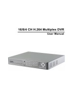
User Manual
16/8/4 CH H.264 Multiplex DVR
This symbol is intended to alert the user to the presence of unprotected “Dangerous voltage"
within the product's enclosure that may be strong enough to cause a risk of electric shock.
This symbol is intended to alert the user to the presence of important operating and
maintenance (servicing) instructions in the literature accompanying the appliance.
WARNING
TO REDUCE THE RISK OF FIRE OR ELECTRIC SHOCK, DO NOT EXPOSE THIS APPLIANCE TO RAIN
OR MOISTURE.
NOTE: This equipment has been tested and found to comply with the limits for a class digital device,
pursuant to part 15 of the FCC Rules. These limits are designed to provide reasonable protection
against harmful interference when the equipment is operated in a commercial environment. This
equipment generates, uses, and can radiate radio frequency energy and, if not installed and used
in accordance with the instruction manual, may cause harmful interference to radio
communications. Operation of this equipment in a residential area is likely to cause harmful
interference in which case the user will be required to correct the interference at his own expense.
Disposal of Old Electrical & Electronic Equipment (Applicable in the European
Union and other European countries with separate collection systems)
This symbol on the product or on its packaging indicates that this product shall not be treated as household
waste. Instead it shall be handed over to the applicable collection point for the recycling of electrical and
electronic equipment. By ensuring this product is disposed of correctly, you will help prevent potential
negative consequences for the environment and human health, which could otherwise be caused by
inappropriate waste handling of this product. The recycling of materials will help to conserve natural
I
VER.:1.0, P/N: 040179A
resources. For more detailed information about recycling of this product, please contact your local city office ,
your household waste disposal service or the shop where you purchased the product.
II
All the safety and operating instructions must be read before the unit is operated.
•
Make sure to switch the power off before you install the DVR.
•
There is the danger of an electric shock if the DVR is opened by an unqualified service
engineer or installer.
•
Avoid using the DVR outside of the reference temperature and humidity indicated in the
specification.
•
Avoid exposing the DVR to violent movement or vibration.
•
Do not use or store the DVR in direct sunlight or near to any source of heat.
•
Do not place any object into the holes used for air circulation.
•
Always use the DVR in a well ventilated location to prevent overheating.
•
Risk of explosion if battery is replaced by an incorrect type.
•
Dispose of used batteries according to the instructions.
•
The recommended HDD types are Samsung Electronic, Western Digital and Seagate.
III
TABLE OF CONTENTS
Chapter 1 Features 1
Chapter 2 Packing Detail 2
Chapter 3 Location and Control 3
3.1 Front Panel Controls 3
3.2 Real Panel Connectors 6
3.3 Remote Controller 7
3.4 Mouse Control 9
Chapter 4 Installation 10
4.1 TOTAL CONNECTION LAY-OUT 10
4.2 HDD INSTALLATION 11
4.3 MAIN DEVICES INSTALLATION 13
4.3.1 Camera 13
4.3.2 Audio 13
4.3.3 Monitor 14
4.4 SENSOR INPUT 17
4.4.1 Sensor Input Menu Setup 17
4.5 RS-485 18
4.5.1 RS-485 Menu Setup 18
4.5.2 PTZ Camera Installation 18
4.5.3 PTZ Camera Operation 19
4.5.4 PTZ Camera Preset Mode 19
4.6 Relay Output 20
Chapter 5 Basic Operation and Menu Setup 22
5.1 Basic Operation 22
5.1.1 Power ON/OFF 22
5.1.2 Screen Display 22
5.1.3 System Status 23
5.1.4 Audio Control 24
5.1.5 PIP Mode 24
5.1.6 DIGITAL ZOOM 25
5.1.7 Menu Operation 25
5.2 SCREEN 26
5.2.1 AUTO SEQUENCE 26
5.2.2 DISPLAY 27
5.2.3 TITLE 28
5.2.4 COVERT 28
IV
5.2.5 SPOT 29
5.2.7 CAMERA 30
5.3 SYSTEM 30
5.3.1 HDD 30
5.3.2 CLOCK 31
5.3.3 VIDEO STANDARD 32
5.3.4 LANGUAGE 32
5.3.5 REMOTE CONTROL ID 32
5.3.6 KEY ECHO 32
5.3.7 ADVANCED SETUP 33
5.3.8 FIRMWARE UPGRADE 35
Chapter 6 Record Operation and Menu Setup 36
6.1 Record Operation 36
6.2 QUICK SETUP 37
6.3 RECORD SETUP 39
6.4 EVENT SETUP 40
6.4.1 MOTION DETECTION 40
6.4.2 EVENT SCREEN MODE 41
6.4.3 EVENT MESSAGE 41
6.4.4 EVENT MESSAGE RESET 41
6.4.5 EVENT BUZZER 41
6.4.6 EVENT RECORD 41
6.5 OTHER RECORD SETUP 43
6.5.1 PREVIEW QUALITY 43
6.5.2 AUDIO RECORD 44
6.5.3 REPEAT RECORD 44
6.5.4 PLAY MODE 44
6.5.5 HOLIDAY 44
Chapter 7 Search Operation and Menu Setup 46
7.1 CALENDAR SEARCH 46
7.2 SEARCH© 47
7.3 TIME SEARCH 47
7.4 EVENT SEARCH 48
7.5 BLOCK SEARCH 48
7.6 FILE SEARCH 49
7.7 BOOKMARK SEARCH 49
7.8 LOG FILE SEARCH 50
7.9 SEARCH BUTTON INFORMATION 50
Chapter 8 Copy Operation and Menu Setup 53
V
8.1 COPY 53
8.1.1 Copy to USB Storage Device 53
8.1.2 Copy to DVD±RW 54
8.1.3 STOP COPY 54
8.1.4 CONTINUE COPY 54
8.2 COPY STATUS 55
8.3 FORMAT MEDIA 55
Chapter 9 Network Setup and Operation 57
9.1 NETWORK SETUP 57
9.2 DVR-VIEWER INSTALLATION 59
9.2.1 System Requirement 59
9.2.2 Network Environment 59
9.2.3 Installation Steps 59
9.3 DVR-Viewer Control Panel Introduction 63
9.4 DVR-Viewer Operation 65
9.4.1 DVR-Viewer Software Password 65
9.4.2 DVR List 65
9.4.3 HDD Search 67
9.4.4 File Search 68
9.4.5 Arrange Windows 68
9.4.6 Viewer Option 69
9.4.7 Display 70
9.4.8 DVR Controller 71
9.4.9 PTZ Controller 71
9.4.10 SETUP 72
9.4.11 STATUS 75
9.4.12 PRINT 76
9.4.13 COPY 77
9.4.14 SEARCH 77
9.4.15 Record and Playback Control Buttons 77
Chapter 10 Additional Function Operation and Menu Setup 79
10.1 E-mail 79
Chapter 11 Specification 81
The author assumes no responsibility for any errors or omissions that may appear in this
document nor does the author make a commitment to update the information herein.
VI
Chapter 1 Features
H.264 compression for DVR recording and web transmission
Graphic OSD and mouse control(PS/2)
Live display, record, backup, playback and network access as the same time
DVD writer (optional) and USB device backup
Remote view and manage through 16CH client software and IE browser
Audio recording
Motion detection with area selecting and sensitivity adjusting by each camera
Remote controller
Email notification
Control all functions of PTZ camera
TCP/IP, DHCP, DDNS, Dynamic IP network protocol
System auto recovery after power reconnected
Watermark proof
Manual / event / schedule recording
Multi-language OSD: English /Polish / Spanish / Russian / Traditional Chinese / French / Turkish /
German / Italian / Portuguese
1
Chapter 2 Packing Detail
1. DVR
2. Client Viewer Software CD 3. User Manual 4. Remote Controller
5. Power Cord 6. Power Adapter 7. Battery
CONTENTS
1. DVR
2. Client Viewer Software CD
3. User Manual
4. Remote Controller
5. Power Cord
6. Power Adapter
7. Battery
2
Chapter 3 Location and Control
3.1 Front Panel Controls
Item
Description
1 DVD-RW A DVD-RW drive is installed in the front bay. (sold separately)
2 EJECT Press EJECT button to open/close the DVD-RW drive.
3 IR RECEIVER Infrared signal receiver for the IR remote controller. Do not block the
receiver as a clear line of sight is required for proper operation.
4 NUMERIC BUTTON /
CHANNEL SELECT
(a) selects a specific channel number to be displayed in full
screen
(b) enter the numeric password when prompted
(c) number 0 for audio function
5 PLAY / PAUSE
( )
/ Z(-) (a) Starts the playback of recorded data. By default, the playback
starts from the earliest recording.
(b) Toggles between playback and pause mode
(c) Zoom out (PTZ mode)
6 FAST
( ) /Z(+)
(a) Fast forward. Press this button repeatedly to toggle
between 2X normal playback speed through 128X normal
playback speed.
(b) Zoom in (PTZ mode)
7 RECORD
(
)
This button starts and stops the recording mode.
8 STATUS LED Displays the status of the DVR (standby), HDD read/write and
network transmission.
9 ALARM RESET / LEFT
DIRECTION BUTTON
(
)
(a) resets the alarm buzzer
(b) left pans in PTZ mode
(c) navigates left in the menu screen
(d) moves the zoom box left in zoom mode
1
2
3
4
5
6
7
8
9
10
11
12
13
14
15
16
17
18
19
20
21
22
23
24
25
3
10 MENU / UP DIRECTIONAL
BUTTON
(
)
(a) accesses the main menu screen
(b) tilts up in PTZ mode
(c) navigates up in the menu screen
(d) moves the zoom box up in zoom mode
11 PIP / LOOP PLAYBACK
CLEAR / DOWN
DIRECTIONAL BUTTON
(
)
(a) activates the picture-in-picture mode
(b) tilts down in PTZ mode
(c) navigates down in the menu screen
(d) moves the zoom box down in zoom mode
(e) clears the loop playback in playback mode
12 DIGITAL ZOOM / RIGHT
DIRECTIONAL BUTTON
(
)
(a) enters digital zoom mode
(b) pans right in PTZ mode
(c) navigates right in the menu screen
(d) moves the zoom box right in zoom mode
13 USB 2.0 The USB 2.0 port can be used to connect to numerous USB 2.0
backup devices.
14 MULIT (DISPLAY) This button is used to toggle between multiple display modes: 16,
13, 10, 9, 7, 6 and 4 channel split screen display modes.
15 SLOW
( )/
IRIS CLOSE / PIC
BY PIC
(a) Slow playback. Press this button repeatedly to toggle
between 1/2 normal playback speed through 128 normal
playback speed.
(b) Control the iris close in PTZ mode
(c) control the playback picture by picture
16 PTZ / BOOKMARK (a) enters PTZ control mode
(b) creates a bookmark during playback mode
17 DIRECT ION
( )
(a) Change the playback direction.
(b) Control the iris open in PTZ mode
(c) Control the playback picture by picture
18 COPY / AUTO FOCUS (a) enters the copy menu screen
(b) switches the PTZ camera to auto focus mode in PTZ
mode
19 STOP (
■
) Switches the Playback mode to LIVE mode.
20 SEARCH / PRESET (a) enters the search menu screen
(b) sets the preset positions in PTZ mode
21 SPOT MONITOR / ESC (a) Activates the spot monitor control
(b) Returns to previous menu screen
(c) Exits from various function and menu screen
4
22 ENTER / STATUS / HOME (a) executes the selected function in the menu screen or
enters the selected submenu
(b) accesses the status window from the main screen
(c) returns the PTZ camera to “home” mode in PTZ mode
(d) increases the digital zoom ration in zoom mode
23 AUTOMATIC SEQUENCE /
FOCUS OUT / DECREASSE
VALUE / SECTION A
(a) activates and deactivates the automatic channel sequence
(b) focuses out in PTZ mode
(c) decreases the value of a selection in the menu screen
(d) sets the starting point for loop playback in playback mode
24 FREEZE / FOCUS IN /
INCREASE VALUE /
SECTION B
(a) freezes the live screen
(b) focuses in PTZ mode
(c) increase the value of a selection in the menu screen
(d) sets the ending point for loop playback in playback mode
25 FUNCTION
Use with other buttons.
5
3.2 Real Panel Connectors
4CH DVR
DC 12V
ETHERNET
VGA
ON
OFF
IN
OUT
SPOT3
4
1
2
VGA
3
4
1
2
SENSOR 485 RL1
ON
OFF
DC 12V
DC 12V
ON
OFF
ETHERNET
ETHERNET
VGA
3
4
1
2
7
8
5
6
7
8
5
6
11
12
9
10
15
16
13
14
SENSOR
RISK OF ELECTRIC SHOCK
DO NOT OPEN
TO REDUCE THE RISK OF
FIRE OR ELECTRIC SHOCK
CAUTION !
WARNING:
RISK OF ELECTRIC SHOCK
DO NOT OPEN
TO REDUCE THE RISK OF
FIRE OR ELECTRIC SHOCK
CAUTION !
WARNING:
RISK OF ELECTRIC SHOCK
DO NOT OPEN
TO REDUCE THE RISK OF
FIRE OR ELECTRIC SHOCK
CAUTION !
WARNING:
SENSOR
VIDEO IN
VIDEO OUT
AUDIO
G G
NO
CM
D
+
D
-
3
4
1
2
G
G
IN
OUT
SPOT
VIDEO OUT
AUDIO
VIDEO IN
IN
OUT
SPOT
VIDEO OUT
AUDIO
VIDEO IN
485 RL1G G
3
4
1
2
G
G
7
8
5
6
485 RL1G G
3
4
1
2
G
G
7
8
5
6
11
12
9
10
15
16
13
14
PS/ 2
PS/ 2
PS/ 2
NO
CM
D
+
D
-
NO
CM
D
+
D
-
8CH DVR
DC 12V
ETHERNET
VGA
ON
OFF
IN
OUT
SPOT3
4
1
2
VGA
3
4
1
2
SENSOR 485 RL1
ON
OFF
DC 12V
DC 12V
ON
OFF
ETHERNET
ETHERNET
VGA
3
4
1
2
7
8
5
6
7
8
5
6
11
12
9
10
15
16
13
14
SENSOR
RISK OF ELECTRIC SHOCK
DO NOT OPEN
TO REDUCE THE RISK OF
FIRE OR ELECTRIC SHOCK
CAUTION !
WARNING:
RISK OF ELECTRIC SHOCK
DO NOT OPEN
TO REDUCE THE RISK OF
FIRE OR ELECTRIC SHOCK
CAUTION !
WARNING:
RISK OF ELECTRIC SHOCK
DO NOT OPEN
TO REDUCE THE RISK OF
FIRE OR ELECTRIC SHOCK
CAUTION !
WARNING:
SENSOR
VIDEO IN
VIDEO OUT
AUDIO
G G
NO
CM
D
+
D
-
3
4
1
2
G
G
IN
OUT
SPOT
VIDEO OUT
AUDIO
VIDEO IN
IN
OUT
SPOT
VIDEO OUT
AUDIO
VIDEO IN
485
RL1G G
3
4
1
2
G
G
7
8
5
6
485 RL1G G
3
4
1
2
G
G
7
8
5
6
11
12
9
10
15
16
13
14
PS/ 2
PS/ 2
PS/ 2
NO
CM
D
+
D
-
NO
CM
D
+
D
-
16CH DVR
DC 12V
ETHERNET
VGA
ON
OFF
IN
OUT
SPOT3
4
1
2
VGA
3
4
1
2
SENSOR 485 RL1
ON
OFF
DC 12V
DC 12V
ON
OFF
ETHERNET
ETHERNET
VGA
3
4
1
2
7
8
5
6
7
8
5
6
11
12
9
10
15
16
13
14
SENSOR
RISK OF ELECTRIC SHOCK
DO NOT OPEN
TO REDUCE THE RISK OF
FIRE OR ELECTRIC SHOCK
CAUTION !
WARNING:
RISK OF ELECTRIC SHOCK
DO NOT OPEN
TO REDUCE THE RISK OF
FIRE OR ELECTRIC SHOCK
CAUTION !
WARNING:
RISK OF ELECTRIC SHOCK
DO NOT OPEN
TO REDUCE THE RISK OF
FIRE OR ELECTRIC SHOCK
CAUTION !
WARNING:
SENSOR
VIDEO IN
VIDEO OUT
AUDIO
G G
NO
CM
D
+
D
-
3
4
1
2
G
G
IN
OUT
SPOT
VIDEO OUT
AUDIO
VIDEO IN
IN
OUT
SPOT
VIDEO OUT
AUDIO
VIDEO IN
485
RL1G G
3
4
1
2
G
G
7
8
5
6
485 RL1G G
3
4
1
2
G
G
7
8
5
6
11
12
9
10
15
16
13
14
PS/ 2
PS/ 2
PS/ 2
NO
CM
D
+
D
-
NO
CM
D
+
D
-
Item
Description
1 VIDEO IN BNC input ports for cameras
2 SPOT BNC output port for spot monitor
3 VIDEO OUT BNC output port for the main monitor
4 AUDIO IN RCA input port for an audio signal
5 AUDIO OUT RCA output port for an audio signal
6 VGA Output port for the VGA monitor
7 PS/2 PS/2 mouse connection port
8 ETHERNET Port for 10/100Mbps Ethernet
9 SENSOR/RS-485/
RELAY OUT
Input terminal blocks for alarm signals/Terminal blocks of RS-485/Relay
output termainal blocks
10 POWER IN Socket for DC 12V power adapter
11 POWER SWITCH Switch to turn the power on/off
1
2
3
4
5
6
7
8
9
10
11
1
2
3
4
5
6
7
8
9
10
11
1
2
3
4
5
6
7
8
9
10
11
6
3.3 Remote Controller
按按按按
按按
COPY/AF
Enter the COPY menu / Auto Focus
Mode (PTZ control mode)
(SEARCH) / PRESET Enter the SEARCH menu / sets the
preset positions in PTZ mode
PTZ / BOOKMARK Enter PTZ control mode / creates a
bookmark during playback mode
Z- Zoom Out (PTZ control mode)
Z+ Zoom In (PTZ control mode)
IRIS - Control the iris close in PTZ mode
IRIS+ Control the iris open in PTZ mode
ESC Exit / Activates the SPOT monitor
control
FUNCTION Use with other buttons
(
▲
) / MENU Up directional button / Enter Menu
Setup
AR/ RESET / (
◀
) Alarm reset / Left directional button
(
▼
) / (PIP) Down directional button / Enter the
PIP mode
DIGITAL ZOOM / (
▶
) Enter Digital Zoom mode / Right
directional button
ENTER Enter / Enter the STATUS menu
F(-) Decreases the value of a selection /
Activates and deactivates the
automatic channel sequence
F(+) Increases the value of a selection /
Freezes the LIVE screen
PLAY / PAUSE ( ) PLAY / PAUSE
SLOW ( ) Slow playback
FAST ( ) Fast forward
DIR ( ) Change the playback direction
RECORD ( ) Starts and stops the recording mode
LIVE/PB / (
■
) Switches the LIVE mode and
Playback mode / STOP
AUDIO Audio function
MULTI Multi display mode
7
CAMERA BUTTONS Numeric button / Channel select
REMOTE CONTROLLER ID
REMOTE CONTROLLER ID
8
3.4 Mouse Control
Double-click of the left button
Status display
One-click of the right button Menu display
Double-click of the right button
Exit
Turning the wheel scroll
Value change
Double-click on the item or icon
Select
9
Chapter 4 Installation
4.1 TOTAL CONNECTION LAY-OUT
CAMERA 1~16
SPOT MONITOR
MAIN MONITOR
VGA MONITOR
LINE AUDIO
10
4.2 HDD INSTALLATION
First, please remove the HDD holder from the DVR machine. (Pic1)
。
(Pic1)
Lock HDD holder symmetirically in the two sides of HDD. (Pic2, Pic3)
(Pic2) (Pic3)
Insert the SATA cable and power cable into SATA HDD. (Pic4)
(Pic4)
11
Lock the HDDs onto DVR machine. (Pic5)
。
(Pic5)
Insert the SATA cables into the sockets on the main board (Pic6). Make sure the HDD1 cable insert into
HDD1 socket. Now, the installation was finished (Pic7).
(Pic6) (Pic7)
HDD1
12
4.3 MAIN DEVICES INSTALLATION
4.3.1 Camera
* Connect a female BNC connector of each camera to a male BNC connector, “CAMERA IN” port.
4.3.2 Audio
CAMERA 1~16
13
Audio Input
- AUDIO IN: Connect the RCA Line Jack of the relevant equipment (for example, a camera with a built-in
microphone) to the AUDIO IN port.
Audio Output
- AUDIO OUT: Connect the RCA Line output to a monitor with a built-in speaker.
NOTE
- This DVR can be connected only with a line audio and not support a microphone for audio input and
output. To record audio should be enable in the AUDIO setup at the MENU setup.
- You can hear the audio under LIVE mode and Playback mode. And select any one channel’s audio and
image input from full-screen mode or multi-display mode.
4.3.3 Monitor
LINE AUDIO
14
SPOT MONITOR
MAIN MONITOR
VGA MONITOR
DVR supports two types of monitor output, one is Composite output (BNC connector); the other one is VGA
output (DSUB-15). But you can just select one monitor output type at a time.
* Composite Output:
(1) Power off
(2) Press the MENU button and CH3 button at the same time
(3) Power on
(4) When you hear a beep sound, it means images already output to the Composite port. Now you can
release the buttons.
* VGA Output:
(1) Power off
(2) Press the MENU button and CH4 button at the same time
(3) Power on
(4) When you hear a beep sound, it means images already output to the VGA port. Now you can release
the buttons.
15
16
4.4 SENSOR INPUT
16CH: SENSOR 1~SENSOR 16
8CH: SENSOR 1~SENSOR 8
4CH: SENSOR 1~SENSOR 4
4.4.1 Sensor Input Menu Setup
Enter EVENT -> SENSOR INPUT menu to select the correct sensor input type which connected with DVR.
Select the right sensor type according to the type of installed sensor with the unit.
- NORMAL OPEN: The sensor is open in normal times.
- NORMAL CLOSE: The sensor is close in normal times.
- NOT INSTALLED: No sensors are connected to the DVR unit
17
4.5 RS-485
RS485 is use for connect to external device, such as keyboard or PTZ camera.
4.5.1 RS-485 Menu Setup
Enter LINK -> RS485 menu to set the parameters of RS-485 device which connected with DVR (The
parameters must the same with the device).
4.5.2 PTZ Camera Installation
Connect the PTZ camera to DVR RS-485 interface (D+ to D+; D- to D-), and then connect the camera
output to the desired channel.
Enter LINK -> PTZ menu to set the parameters of PTZ camera which connected with DVR (The parameters
18