Robotic Subsurface Mapping Using Ground Penetrating Radar doc
Bạn đang xem bản rút gọn của tài liệu. Xem và tải ngay bản đầy đủ của tài liệu tại đây (1.82 MB, 143 trang )
Robotic Subsurface Mapping Using
Ground Penetrating Radar
Herman Herman
CMU-RI-TR-97-19
Submitted in partial fulfillment of the
requirements for the degree of
Doctor of Philosophy in Roboticss
The Robotics Institute
Carnegie Mellon University
Pitsburgh, Pennsylvania 15213
May 1997
© 1997 by Herman Herman. All Rights reserved.
ii
iii
Abstract
The goal of our research is to develop an autonomous robot for subsurface mapping. We are
motivated by the growing need for mapping buried pipes, hazardous waste, landmines and
other buried objects. Most of these are large scale mapping problems, and to manually con-
struct subsurface maps in these cases would require a significant amount of resources.
Therefore, automating the subsurface mapping process is an important factor in alleviating
these problems.
To achieve our goal, we have developed a robotic system that can autonomously gather and
process Ground Penetrating Radar (GPR) data. The system uses a scanning laser rangefinder
to construct an elevation map of an area. By using the elevation map, a robotic manipulator
can follow the contour of the terrain when it moves the GPR antenna during the scanning
process. The collected data are then processed to detect and locate buried objects. We have
developed three new processing methods, two are volume based processing methods and
one is a surface based processing method. In volume based processing, the 3-D data are
directly processed to find the buried objects, while in surface based processing, the 3-D data
are first reduced to a series of 2.5-D surfaces before further processing. Each of these meth-
ods has its own strengths and weaknesses. The volume based processing methods can be
made very fast using parallel processing techniques, but they require an accurate propaga-
tion velocity of the GPR signal in the soil. On the other hand, the surface based processing
method uses 3-D segmentation to recognize the shape of the buried objects, which does not
require an accurate propagation velocity estimate. Both approaches are quite efficient and
well suited for online data processing. In fact, they are so efficient that the current bottleneck
in the subsurface mapping process is the data acquisition phase.
The main contribution of the thesis is the development of an autonomous system for detect-
ing and localizing buried objects. Specifically, we have developed three new methods to find
buried objects in 3-D GPR data. Using these methods, we are able to autonomously obtain
subsurface data, locate and recognize buried objects. These methods differ from existing
GPR data processing methods because they can autonomously extract the location, orienta-
tion, and parameters of the buried object from high resolution 3-D data. Most existing meth-
ods only enhance the GPR data for easier interpretation by human experts. There are some
existing works in automated interpretation of GPR data, but they only work with 2-D GPR
data. We implemented the three different methods and also tested them by building subsur-
face maps of various buried objects under different soil conditions. We also used these sub-
surface mapping methods to demonstrate an autonomous buried object retrieval system. In
summary, we have developed a robotic system which make subsurface mapping faster, more
accurate and reliable.
iv
v
Acknowledgments
Foremost I would like to thank Anthony Stentz for his guidance and support for the last 5
years. He was always open to my ideas, gave thoughtful comments, and asked tough ques-
tions. In short, Tony is a great advisor.
I also would like to thank Andy Witkin for his guidance and support during the early years
of my graduate career. What I learned during those years has proved to be invaluable in my
research.
Thanks to Mike Heiler for introducing me to Ground Penetrating Radar and subsurface
mapping. Without his help in setting up the testbed, many experiments would not have been
possible. Thanks to James Osborn for his support and constructive comments on the subject
of subsurface mapping.
Thanks to Sanjiv Singh for his collaboration on the subsurface mapping testbed. The dem-
onstration of the autonomous buried object retrieval system would not have been possible
without his help. Thanks to Mike Blackwell and Regis Hoffman for help with the laser scan-
ner.
Thanks to Behnam Motazed, Jeffrey Daniels, Hans Moravec and Martial Hebert for agree-
ing to be on my thesis committee and for their thoughtful comments on the research.
Thanks to my officemates, Dave Wettergreen, Dimitrious Apostolopoulos, Mike Heiler, and
Sanjiv Singh for their friendship and willingness to help on various occasions.
Thanks to Red Whittaker for founding the Field Robotics Center and providing the inspira-
tion for many of us to do research in robotics. The support of many wonderful people in this
organization has made the research considerably better.
Thanks to my father and mother. None of this would have been possible without their con-
tinuing love and support. I especially thank them for believing in me and teaching me that
with hard work, I can reach all my goals in life. Thanks to my brother and sisters, Maman,
Nany and Wawa, for their support and encouragement.
Finally, I would like to thank my wife Lingga for her love and support during the past couple
of years, and Baylee for faithfully accompanying me during the long hours of work.
vi
vii
Table of Contents
1. Robotic Subsurface Mapper 9
1.1. Introduction to Buried Object Mapping Problem 9
1.2. Research Objective 12
1.3. Technical Approach 13
1.4. Rationales 18
1.5. Applications of the Robotic Subsurface Mapper 19
2. Related Work 23
2.1. Subsurface Mapping 23
2.2. Automated Excavation and Buried Object Retrieval 26
3. Ground Penetrating Radar 29
3.1. Selection of Subsurface Sensors 29
3.2. GPR Data Collection and Data Format 37
3.3. Analysis of Different Antenna Array Configurations 39
3.4. GPR Data Visualization 43
3.5. 2-D Visualization 44
3.6. 3-D Visualization 50
3.7. GPR Data Processing and Interpretation 53
3.8. Example of GPR Data 55
4. Volume Based Processing 59
4.1. Overview of Volume Based GPR Data Processing 59
4.2. Background Noise Removal 60
4.3. 3-D Migration Using Coherent Summation 61
4.4. 3-D Migration using Reflector Pose Estimation 70
viii
5. Surface Based Processing 95
5.1. Overview of Surface Based GPR Data Processing 95
5.2. Preprocessing 96
5.3. 3-D Segmentation 102
5.4. Surface Type Categorization 105
5.5. Parameter Estimation 108
5.6. Parametric Migration 110
5.7. Propagation Velocity Computation 111
5.8. Limitation of the Surface Based Processing 112
5.9. Analysis and Result 113
6. Subsurface Mapping Testbed 127
6.1. Testbed Description 127
6.2. Software Architecture 129
6.3. An Example of Mapping and Retrieval of a Buried Object 132
7. Conclusions 135
7.1. Conclusion 135
7.2. Contribution 137
7.3. Future Direction 138
8. References 139
9
Chapter 1. Robotic Subsurface Mapper
1.1. Introduction to Buried Object Mapping Problem
Over the last several decades, human has buried a large amount of hazardous waste, unex-
ploded ordnance, landmines and other dangerous substances. During war periods, armies of
different nations have buried millions of landmines around the world. A significant number
of these landmines are still buried and active. They annually claim a significant number of
innocent lives and maim many more people. Many people and companies have also improp-
erly buried hazardous toxic wastes at various sites. As the containers that hold the toxic
waste age, their conditions deteriorate, necessitating the need for retrieving and moving
them to safer places. United Stated also has many military training sites which contains a
huge number of unexploded ordnances. These sites can not be reused for civil applications
until those unexploded ordnances are removed.
Finding these buried objects is hard because accurate maps, denoting where the objects are
buried, rarely exist. In some cases, the lack of accurate map is deliberate, such as in the case
of landmines. In some other cases, the maps are accidentally lost, as in the case of some bur-
ied hazardous waste sites. Even if the maps exist, vegetation or land-fill may have signifi-
cantly transform the soil surface, rendering the maps unusable. Regardless of the reasons,
remediators now need to find the precise locations of these buried objects.
10
Finding buried objects is also important in maintaining subsurface structures. We all have
heard news of utility workers accidentally cutting phone or electrical lines. This happens
because they do not know that there are buried utility structures at the excavation site. Even
if a subsurface map of all buried structures exist, there is still a problem of registering the
position of a buried structure in the map with its actual location in the world. It would be
much easier if the workers could scan an area right before they excavate it and determine if
there is any buried objects under it.
These are just a few examples which illustrate the growing need to find buried man-made
objects. In some cases, remediation of these problems may also necessitate the retrieval of
the buried objects. The scale of these problems is very large. We need to find and remove
millions of landmines, and clean up hundreds of hazardous waste sites. Presently, the con-
ventional remediation process is very time consuming and prone to errors. In order to under-
stand the reason, let us examine how the remediation process is usually done.
Currently the conventional approach to this problem involves a sequence of manual opera-
tions. First, remediators scan an area using a sensor that could sense buried objects. The
amount of data produced by the sensor is proportional to the size of the area. If the area is
quite large, the sensor can easily generate immense amount of data. The sampling interval of
the scanning process also affects the amount of data. As the sampling interval gets denser,
the sensor produces higher resolution data for the same area, resulting in a larger amount of
data. Experts then need to interpret the large amount of data in order to find the buried
objects. This interpretation process could easily last for several days or weeks, depending on
the size of the data. Once the experts find the buried objects in the data, they need to deter-
mine their actual locations in the world. The process of determining the actual location of an
object from its position in the sensor data is called the registration process. Depending on
how carefully the data are gathered, inaccurate registration will result in significant errors in
the locations of the objects. As a result of these registration errors, the remediators would
not find the buried objects at the computed locations. To minimize this problem, the position
of the sensor during scanning is often measured by surveying equipments. The surveying
activities result in a more accurate registration at the expense of longer scanning time.
The above series of steps is called subsurface mapping. It involves scanning an area using a
sensor that can sense buried objects, and finding the buried objects in the sensor data. Once
we have the subsurface map, then we can start addressing the buried object retrieval process.
The retrieval process also comes with its own set of problems. Many of the buried objects
are hazardous to human and when they experience excessive forces, they can explode or, in
the case of hazardous waste containers, their content can leak out. Heavy excavators are usu-
ally used to extricate these buried objects, and they can unintentionally apply excessive
forces to the buried objects because the operator does not always know the location of the
11
excavator bucket with respect to the buried objects. The operator knows that the objects is
located at a certain location or depth, but he/she has no information as to the relative loca-
tion of the excavator bucket with respect to the buried objects. As a result, only a very thin
layer of soil can be removed at a time to minimize the possibility of collision with the buried
objects. Various mechanical solutions have also been tried. An example is an excavator that
uses air jet to loosen the soil material and then remove the loose material using a vacuum
suction device. Such mechanical solutions only work in some situations, depending on the
soil type and the amount of soil that needs to be removed. A better solution would be to
install a positioning device to determine the location of the bucket during excavation. Using
the device, we can compute the relative position of the bucket with respect to the buried
objects. Therefore, the possibility of collision is minimized, although the human operator is
still exposed to possible danger from the buried objects.
We conclude that the current approaches to subsurface mapping and retrieval process are
very time consuming and expose the remediators to unnecessary dangers. As a result, reme-
diation of these buried objects is often a very costly proposition. We argue that we need to
automate some of these steps. Automation could both lower the cost and shorten the time
needed to perform the necessary steps. Our ultimate goal is to develop an autonomous robot
that can find and retrieve buried objects. This robot would gather necessary subsurface data,
interpret it, and retrieve the buried objects. We envision that the robot would consists of a
computer controlled excavator, a subsurface sensor, and computers to control the mecha-
nism and to interpret the sensor data. Using the robot, we would eliminate the operator
exposure to danger from explosion or leaked chemical caused by collision with buried
objects.
In this thesis, we address part of the problem, which is developing a robotic subsurface map-
per to find buried objects autonomously. Specifically, we are developing algorithms that can
automatically find buried objects using Ground Penetrating Radar (GPR) data. These algo-
rithms are very important parts of the overall solution for autonomously finding and retriev-
ing buried objects. We will show the development of the algorithms and the experimental
results which prove their feasibility.
In the rest of this chapter we will explain the objective, technical approach, rationales and
typical applications of our research. The issue of integrating subsurface mapping with bur-
ied objects retrieval will also be discussed in this chapter. In chapter 2, we will review exist-
ing works that have been done in the area of subsurface mapping and how they relate to our
research. In chapter 3, we will explain the principle and operation of Ground Penetrating
Radar (GPR), which is the sensor that we use to sense buried objects. Its limitations and dif-
ferent visualization techniques for its data will also be discussed. We will also examine the
shortcomings of manual GPR data interpretation and the advantages of automatic GPR data
interpretation. Chapter 4 and 5 will cover two different types of algorithms that we devel-
12
oped and implemented to automatically find buried objects in GPR data. Chapter 4 explains
the first two algorithms, which is based on 3-D voxel processing, and chapter 5 explains the
third algorithm, which is based on 3-D surface model based recognition. Each of these
approaches has its own advantages and disadvantages, and in many cases they complement
each other. In each chapter, we will also present our experimental results for each algorithm
to prove the feasibility of our approaches. In Chapter 6 we will show our experimental test-
bed and explain how we use it for our experiments in subsurface mapping and buried object
retrieval. Finally, chapter 7 contains our conclusions and future directions for our research.
1.2. Research Objective
Our research objective is the following:
"Develop an intelligent robotic subsurface mapper that can autonomously
detect, locate and compute geometric parameters of buried objects"
We will refer to the problem of detecting, locating and computing geometric parameters of
buried objects as the problem of "Subsurface Mapping". The geometric parameters of a bur-
ied object include its size, shape, and 3-D orientation
To achieve the objective, the robotic subsurface mapper must be able to satisfy the following
requirements:
1. Scan the soil surface and build a terrain elevation map to guide sen-
sor placement.
2. Scan the subsurface using a subsurface sensor.
3. Detect, locate and measure buried object from the subsurface sensor
data.
4. Display the subsurface data and the buried object to the operator for
notification and confirmation.
If retrieval of the buried objects is necessary then we need two additional requirements:
5. Expose the object by excavating the soil above the object.
6. Retrieve the object.
This thesis concentrates on requirement 1, 2, 3 and 4 which address the problem of subsur-
face mapping for buried objects. One of our success criteria is to shorten the time needed for
subsurface mapping, so the solution to these requirements should be faster than manual
approaches.
13
We are not directly addressing the requirements 5 and 6 for retrieval of buried objects, but
we take into account the fact that the subsurface mapping process must be able to be inte-
grated well with the retrieval process. In fact, we found that the ability to remove the soil
above the buried objects actually makes the subsurface mapping problem easier. We will
show how we can get a more accurate subsurface map by repeatedly removing a layer of soil
above the objects and rescan the buried objects.
Although we are developing an autonomous system for building subsurface map. It is possi-
ble to keep a human operator in the loop for safety and high-level planning. Instead of gath-
ering and interpreting the data, the operator acts as a supervisor for the intelligent robot. In
critical operation involving unexploded ordnance retrieval, an expert operator can help guid-
ing the sensing and retrieval process so the fuse of the ordnance can be located. In cases
where the system fails to correctly interpret the subsurface data or fails to plan an appropri-
ate automated excavation, an expert operator can also help the system by providing addi-
tional information.
1.3. Technical Approach
In this section, we will address our technical approach to subsurface mapping. We will
describe the sensor that we use to sense buried objects and how we process the output of the
sensors to find the buried objects. We also address the very important issue of integrating
subsurface mapping with buried object retrieval process by proposing a technique that can
be used to create a more accurate subsurface map during the retrieval process.
1.3.1. Subsurface Mapping
Our technical approach to the subsurface mapping problem uses a robotic mechanism to
move the sensor and automated data processing techniques to find the buried objects in the
sensor data. In our work, the robot consists of an industrial manipulator as the scanning plat-
form for the sensor, a scanning laser rangefinder to map the terrain shape, and a sensor
mounted at the end effector to sense buried objects. First, the robot maps the terrain shape
using its scanning laser rangefinder. It uses the elevation map to guide the manipulator so it
can follow the contour of the terrain during scanning. The robot also tags the sensor data
with the sensor position, so we will be able to accurately register the position of a buried
object in the sensor data to its actual location.
We use Ground Penetrating Radar (GPR) as the robot’s subsurface sensor. GPR is one of the
most versatile sensors for sensing buried objects. It can sense nonmetallic as well as metallic
objects under various soil conditions. When it scans a 2-D area, it produces a 3-D volume
data. With suitable processing, this 3-D volume data can provide us with the location, orien-
tation, size and shape of the buried objects. Currently, most GPR data are interpreted manu-
14
ally by human experts. They examine the data to find the buried objects, and compute their
location, orientation and shape. This is a very time consuming process and prone to interpre-
tation errors. We suggest that a better solution would be to automate the interpretation pro-
cess. To achieve this, we have developed and implemented three new algorithms that can
automate the process of finding buried objects in GPR data, and computing their location,
orientation, size and shape. These algorithms are based on 3-D computer vision methods,
and they reduce the GPR 3-D volume data into a few object’s parameters.
Two of these algorithms directly process the volume data to find the buried objects. We call
this approach, "Volume Based Processing". To further accelerate the execution times of the
algorithms, we modified one of the algorithm so it can be run on multiple processors. Due to
the local nature of the computation, the 3-D data can be split up into smaller pieces and each
pieces can be computed on different processor. So by adding additional processors, we can
reduce the execution time of the algorithm. This is true until the number of processors
becomes large enough that the communication between the processors become a bottleneck.
In our experiment we use as many as 10 processors to run our algorithm without experienc-
ing communication bottleneck.
The third algorithm reduces the 3-D volume data into a series of possible objects’ surfaces
and then uses model based recognition techniques to determine if any of these surfaces
belongs to a buried object. We call this approach "Surface Based Processing". This approach
is much less sensitive to the problem caused by the soil inhomogeneity, since it finds the
objects by detecting their shapes. The shapes appear similar under various soil conditions.
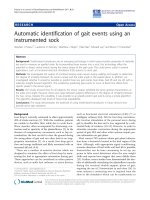
Using these algorithms, along with automated data gathering, the robot can automatically
build the subsurface map of buried objects. The steps that we describe above is illustrated in
Figure 1. As shown in the figure, the subsurface map produced by our algorithms, contains
GPR Data
Acquisition
Volume Based Processing:
- 3-D Segmentation
Object
Surface
Mapping
Parameters:
Surface Based Processing:
Figure 1: Proposed approach for autonomous subsurface mapping
- 3-D Coherent Summation
Migration
- 3-D Reflector Pose
Estimation
- 3-D Pose
- Size
- Shape
Automated Subsurface Mapper
15
some parameters that are previously very hard to get. For example, our automated algo-
rithms can easily compute the object’s 3-D orientation from the 3-D GPR data. In order to
obtain the same information using manual techniques would be very time consuming
because multiple sections of the 3-D data must be examined to compute the 3-D orientation
of a buried object.
1.3.2. Integration of Subsurface Mapping and Buried Object Retrieval
In some cases, subsurface mapping is not enough, we also need to retrieve the buried
objects. During the retrieval process, it is much more important to have a highly accurate
subsurface map. Error in the position estimate of the object may cause collision between the
excavator bucket and the buried object. The acceptable error in the position estimate of the
object depends on the distance of the excavator bucket and the buried object. When the
excavator bucket is digging far away from the buried object, even a large relative error in the
position estimate on the object is acceptable. As the excavator removes layers of soil above
the object and gets closer to the object, we need to have a more accurate estimate on the
position of the object.
Our solution to this problem uses repeated "Scan and Dig Cycle". During each cycle, the
robot rescans the area, regenerates the subsurface map and removes a layer of soil. After
every cycle, the robot gets closer to the buried object and there are less soil between the sen-
sor and the object. Since soil inhomogeneity is one of the main source of error, less soil
between the sensor and the object translates to a smaller error in the position estimate of the
object. As a result we can gradually improve our position estimate of the buried object.
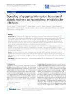
Figure 2 illustrates this concept. The robot consists of a computer controlled excavator with
a subsurface sensor attached to its bucket. It moves the bucket in order to scan an area using
the sensor. Our algorithms then process the scanned data to detect and locate the buried
objects. After an object has been located, the robot would remove a layer of soil above the
object and rescan the are to improve the estimate on the object’s location. It continually
repeat this "Sense and Dig Cycle" until the object is very close to the surface of the soil (Fig-
ure 2d). At this point it will retrieve the object.
The removal of soil serves multiple purposes. First, it needs to be done for the robot to
retrieve the buried object. Second, it enables the sensor to get a better scans of the object by
getting closer to it, thereby improving the accuracy of the subsurface map. Finally, by com-
paring the scans gathered before and after removal of each layer of soil, we can obtain a bet-
ter estimate of the soil parameters. As far as we know, this thesis is the first work which
addresses both issues of automatically processing 3-D GPR data to find buried objects and
integrating the mapping process with the soil removal to improve the estimate on the param-
eters of the buried object and soil.
16
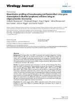
The actions during the sense and dig cycles can be seen in Figure 3. The main assumption of
this approach is that the errors in the subsurface map decrease as we get closer to the buried
objects. The errors can be caused by a wrong GPR propagation velocity estimate and noise
from spurious reflections. Intuitively we can say that as the amount of soil between the
antenna and the object decreases, there are fewer uncertainties in the GPR output. Therefore
we should be able to get more accurate information as we get closer to the object.
This approach is in contrast with existing approaches which try to obtain an accurate and
high resolution subsurface map using a single scan. These existing approaches often fail
because the soil is not homogenous, the penetration depth of the GPR signal is shallow and
the difficulty in interpreting GPR signals that are reflected from deeply buried objects. The
biggest problem with just doing a single subsurface scan in the beginning of the retrieving
process is in obtaining an accurate position and orientation of the buried object. Since the
buried objects may be located at a significant distance from the surface, there are a lot of
uncertainty in the medium between the surface of the soil and the buried object. This uncer-
tainties cause error in the position and orientation estimate of the buried objects. By doing
multiple subsurface scan each time a layer of soil above the object is removed, we can con-
tinually improve the position and orientation estimate. In addition, we can compute a more
accurate parameters of the soil characteristic as we dig deeper to the soil.
Target Object
Computer
Soil
Figure 2: The scenario for retrieving buried object using sense and dig cycle
Excavator bucket equipped with a subsurface sensor
a. Scan the object b. Remove a layer of soil
and scan the object again
c. Remove another layer
of soil and scan the object
d. Retrieve the object
again
controlled
excavator
17
Figure 4 shows the architecture of our integrated robotic subsurface mapper and buried
object retriever. There are 4 main subsystems.First, we have the elevation map generator,
which scans the ground surface to generate an elevation map. The subsurface mapper uses
the elevation map to generate the path for the scanning motion of the sensor. The path is exe-
cuted by the robotic excavator which is equipped with a subsurface sensor at its end effector.
The same robotic excavator is also used for excavating the soil.
Scan the soil surface and the subsurface volume of interest
Compute a lower bound on
the distance to the closest object
Determine if the distance to the closest
object is within threshold
Locate the buried objects in the 3D-data
Yes
Pick Up the
Object
Remove a layer of soil
Figure 3: Processing steps within the sense and dig cycle
(thickness < lower bound on
the distance to the closest object)
Compute propagation velocity by comparing
No
Compute and update object size, shape and location parameter
Sense and
dig cycle
More Objects?
No
Done
Yes
Scan the soil surface and the subsurface volume of interest
Locate the buried objects in the 3D-data
the data gathered before and after the removal of soil
18
1.4. Rationales
Although subsurface mapping can also be done using manual methods, there are several
important rationales for using an autonomous or semi autonomous system to build subsur-
face map. They can be categorized into several different categories:
1.4.1. Improved safety
By having an autonomous system, we can remove the human operators from the operation
site, thus reducing the possible danger to the operators. This is especially true for mapping
sites which contain potentially explosive, radioactive or toxic materials. Although the safety
problem can also be alleviated using teleoperation, the latency and the bandwidth limitation
for low level communication between the teleoperated machine and the operator limit the
type of work that can be done. Autonomous and semi autonomous systems offer much more
flexibility because the communication between the machine and the operator can happen at
several different levels, each of which can be tailored to the task.
Safety is also improved by reducing the possibility of human error in interpreting the sub-
surface sensing output and in registering the objects’ location in the subsurface map with its
Robotic
2-D Laser
Rangefinder
and elevation
map generator
Subsurface
Mapper
Excavation
Planner
Scanning Motion
Volume
of Soil
To Be
Excavated
Dig
Motion
Elevation
Map
Elevation
Map
Figure 4: System Architectures
Excavator
19
actual location in the world. This is possible by using the same mechanism for mapping and
excavating, which will eliminate most of the registration error.
1.4.2. Increased productivity
A fully autonomous system could, in principle, operate continuously day or night. We can
also have multiple systems operating in parallel to speed up the operation. Due to the
absence of human in the operation area, fewer safety precautions need to be taken, which
should also increase the efficiency of the retrieval task. All of these factors contribute to the
increase productivity in term of man hours required for the work.
1.4.3. Cost saving
Many of the applications of this work require mapping and retrieving buried objects in a
wide area, which could easily reach several square miles. Due to the large scale of the prob-
lem, any increase in productivity should result in significant saving in both time and money.
We will also save quite a lot of time and money since the automated system can be operated
by operators with less expertise and skill. This is possible because the difficult process of
data interpretation and low level machine control are done autonomously by the computer.
Autonomous system usually incurs a large one time cost, which is also called the non recur-
ring engineering cost. Once it is working, it can be duplicated at a reduced cost. On the other
hand, a manual system needs experts to operate, which means that each new additional sys-
tem requires training new experts.
1.4.4. New capability
An integrated mapper and excavator will be able to do precise operations that is not possible
with manually operated equipments. Due to the precise information about the object’s loca-
tion and orientation gathered by the mapper, the excavator will be able to excavate soil very
close to the buried object without actually touching the object. Our new improved subsur-
face data processing techniques also generate the object’s location and orientation in 3-D,
compared to existing techniques which mostly generates 2-D information.
1.5. Applications of the Robotic Subsurface Mapper
This work can be applied to many tasks that require subsurface sensing and/or retrieval of
buried object. The following are some example applications in several distinct categories:
20
1.5.1. Subsurface Mapping
1.5.1.1. Mapping of subsurface utility structures
For this application, the robotic mapper builds the map of subsurface structures such as gas
pipes. The subsurface data can be obtained by scanning in a regular grid or by tracking cer-
tain subsurface features, for example by tracking the buried gas pipe individually. Currently
this is done by metal detector or by manual ground penetrating radar (GPR) operation.
Metal detector does not give depth and it only works for metallic pipes. Manual operation of
GPR has its own shortcomings, such as the need for expert operator and the difficulty in get-
ting accurate registration between the location of the pipes in the GPR data and their actual
locations in the world. It is also hard for even an expert to detect some features in the GPR
data.
1.5.1.2. .Detection and mapping of unexploded ordnance and mines
A robotic subsurface mapper would be very useful in detecting and locating landmines. A
robotic subsurface mapper can be deployed in advance of troops to identify a safe route.
Currently landmine detection and localization are done manually using hand-held metal
detectors or mechanical probes. The manual operation is very dangerous and is done at a
very slow pace. Using a robotic landmine mapper, the operation can be made faster by auto-
mating the manual data collection and interpretation task. In addition, we are not risking any
human life in trying to detect and locate the landmines.
1.5.2. Retrieval of Buried Object
1.5.2.1. Retrieval of hazardous waste containers or unexploded ordnance
In this application, the robot needs to map the buried objects, compute their shape and orien-
tation, and generate a plan to remove them. In essence, this application is a continuance of
the detection and mapping of unexploded ordnances or mines. In this application the robot
does not stop when the subsurface objects are detected and located, but it proceeds to deter-
mine their shape and orientation. It uses the additional information to generate a plan to
extricate or neutralize the unexploded ordnance or landmines. Automated scanning and
interpretation are perfect for this application because of the reduced possible error in regis-
tering the location of the object in the GPR data and its location in the real world. The auto-
mated scanning can also collect a very high resolution 3-D data which should increase the
accuracy of the subsurface map.
21
1.5.3. Collision prevention in excavation
1.5.3.1. Maintenance or repair of subsurface structure
In maintaining subsurface structures such as electrical lines, phone lines, or gas pipes, con-
struction crews often need to excavate the soil around the structure. In the process of doing
so, they sometimes hit the structure or other structures that are on their way. For example: a
construction crew from a gas company might have an accurate map of the gas pipes, but dur-
ing the excavation process, the crew might hit and break an electrical line. To prevent this
from happening, the excavator needs to know that the next volume of soil to be excavated is
devoid of any buried objects. So this problem is actually a little bit simpler than the buried
object retrieval problem, since in this application the robotic subsurface mapper only needs
to confirm that a certain volume of soil is devoid of any buried object.
22
23
Chapter 2. Related Work
2.1. Subsurface Mapping
The use of subsurface sensor as a sensing modality has received very little attention in robot-
ics compared to other sensing modalities such as video images, range images or sonar.
Therefore, it is not surprising to find that the proposed robotic subsurface mapper would be
one of the first robotic systems to use a subsurface sensor as one of its sensing modalities. In
this case, the use of the subsurface sensor enables the robot to see through certain solid
medium, such as soil.
While very little work has been done in automated gathering and interpretation of subsur-
face data, there have been quite a lot of work in manual subsurface data gathering and inter-
pretation. In the beginning, subsurface sensing is mainly used for geological explorations
and landmine detections. These are done primarily using sound waves echo recorders or
metal detectors. Many aspects of these two applications are at opposing extremes. Geologi-
cal exploration equipment uses sound waves to scan a very large area, which could easily
reach several square miles. The output of the scanning operation is large and usually used to
map the macroscopic geological features. On the other hand, landmine detection using a
metal detector operates on a much smaller scale. It is usually a point sensor that could detect
a metal object underneath it. The sensor size is usually not more than 1 feet in diameter and
the output of the sensor is usually only a single value denoting the strength of the signal
24
from the metal detection circuit. Subsequently, magnetometer is also used to detect and
locate buried objects. It works by measuring the disturbance created by the buried objects on
the earth magnetic field. Most recently, Ground Penetrating Radar (GPR) is also used for the
detection and localization of buried objects. Lord et al. [Lord 84] did a good overview of
these various subsurface sensing techniques and their characteristics.
Among all the above sensors, GPR might be the most versatile one. As a testament to its
versatility, the variety of its uses has increased significantly during recent years. GPR has
been used in numerous diverse fields such as archaeology [Imai 87], geology [Davis 89],
non-destructive testing [Beck 94][Davis 94] and engineering [Ulricksen 82]. Some of the
specific tasks include mapping soil stratigraphy [Davis 89], probing underground caves
[Deng 94][Vaish 94], detecting landmines [Ozdemir 92], testing roads and runways [Beck
94][Davis 94][Saaraketo 94], mapping pipes and drums [Lord 84][Osumi 85][Gustafson 93]
and locating persons buried under snow [Yamaguchi 91]. Peters and Young [Peters 86] give
good examples of the diverse applications of GPR, while Ulricksen gave a good overview of
the application of GPR in Civil Engineering [Ulricksen 82].
Most of the GPR data gathering and processing is currently done by manually scanning the
area of interest with a handheld antenna or antenna towed by a human-operated motorized
vehicle [Ulricksen 82][Bergstrom 93]. After the data have been obtained then experts exam-
ine the data to find the buried object. These two operations are very time consuming and
prone to many human errors. After the buried object are located in the map, the real location
of the object in the world must be determined. Using this information, a human operated
excavating device can remove the soil above the objects and retrieve the buried objects.
(end)
An important part in solving the detection and mapping of subsurface objects using GPR is
the understanding on how a GPR pulse travels through the soil and is reflected by buried
objects. This involves modeling the GPR system, signal propagation and reflection [Kim
92]. This work is important because through a better understanding of how a GPR system
works is critical in making a better GPR system. Since GPR is a form of radar, many pro-
cessing techniques in radar can also be used for GPR. Therefore it is important to under-
stand the works that have been done in the field of radar signal processing. This is especially
important because conventional radar signal processing is a mature field compare to GPR
signal processing. A good review of modern radar and its processing methods can be found
in the work by Eaves and Fitch [Eaves 87][Fitch 88].
As for the processing of GPR data, researchers have also experimented with multiple tech-
niques to improve GPR data. Due to the similarities between GPR and seismic sensing tech-
nique, there have been some efforts to apply seismic processing methods to GPR, a good
example is the work done by Chang [Chang 89] and Fisher [Fisher 92]. One disadvantage of
25
the seismic processing technique is the massive amount of required computational power. To
alleviate this problem, Fiebrich [Fiebrich 87] and Fricke [Fricke 88] have implemented a
seismic processing method called "Reverse Time Migration" on massively parallel super-
computer. Other optimization methods are also explored to reduce the needed resources in
applying the seismic processing technique [Harris 92]. Due to this massive computational
requirement and other differences between GPR and seismic [Daniels 93], seismic process-
ing methods are ill-suited for realtime subsurface mapping.
Another processing technique that has been studied is the inverse scattering technique
[Moghaddam 92][Oh 92]. This method requires a lot of computational power because the
number of variables that need to be solved during the inverse scattering calculation is very
large. This method also often requires a borehole antenna configuration which involves drill-
ing into the ground. Due to these two problems the practical uses for this method are lim-
ited.
There are also some works dealing with the extraction of buried object’s parameter from
GPR data. Gustafson used a semi-automated method to do velocity depth inversion for
cylindrical objects [Gustafson 93]. He needed to select the direction of the scanning profile
manually. The reflections used in the velocity-depth inversion calculation are obtained by
simple thresholding. Thus, even reflections that come from non-cylindrical objects are
included in the computation if their strength exceeds the threshold. Roberts also used a semi
automated method for velocity-depth inversion to calculate the EM wave propagation veloc-
ity in the soil [Roberts 93]. He assumes the reflection profile comes from a point reflector.
The main disadvantage is that the direction of the scanning profile needs to be manually
selected by the operator. Another work in localization of buried object is the work by Stolte
which uses 2-D migration to highlight the location of buried pipes in the GPR data [Stolte
94]. In our research, we go one step further and uses high resolution 3-D data to find buried
objects. The use of 3-D data in our research eliminates the need to know the orientation of
the buried objects in advance.
These existing works have only addresses some of the issues that we need to solve, such as
the poor lateral resolution of the GPR and the huge amount of data that need to be pro-
cessed. As far as we know, no work has been done in the automated detection and mapping
of buried objects using high resolution 3-D GPR data.
In our research, we use some of the existing methods, such as migration, in combination
with new techniques adapted from computer vision field. To the best of our knowledge we
are the first to use 3-D object recognition techniques to automate the GPR data interpreta-
tion process. It is also important to note that all our work is performed with high resolution
3-D volume data instead of 2-D data, although the methods can be modified so they can be
applied to 2-D data set as well.