Phương pháp mới thiết kế hệ thống điều khiển tốc độ và công suất cho nhà máy thủy điện nhỏ
Bạn đang xem bản rút gọn của tài liệu. Xem và tải ngay bản đầy đủ của tài liệu tại đây (317.5 KB, 7 trang )
T ^ P CHi KHOA HQC & C 6 N G NGHE CAC T R U ' 6 N G DAI HQC KY T H U J L T * S 6 86-2012
NOVEL DESIGN FOR SPEED AND ACTIVE POWER CONTROL OF A SMALL
HYDRAULIC TURBINE
(
PHUONG PHAP MCil THIET KE H$ T H 6 N G DIEU KHIEN TOC DQ VA CONG SUAT
CHO NHA M A Y THUY DIEN NHO
Nguyen Hong Quang
Hanoi University of Science and Technology
Received Mach 31", 2011
\
ABSTRACT
In recent years, the development of small hydro power stations has been widely applied accr
Vietnam. This paper shows the complete design process for a hydro turbine controller The algorith
is given based on the typical mathematical models of the target system. The controller parameters
obtained from the novel analytical formulars. which take into account the wide range of operating
points of hydraulic turbine. In addition, the paper also presents the details design of microcontrolle
based implementation, the use of hardware in loop (MIL) to verify the model in the laboratory condit
The expenence result from hydro controller of Rhyninh hydro turbine unit in Central Vietnam is g
as an illustration.
TOM TAT
Trong nhung nSm gin d§y, vl^c phat trien nha may thuy dien nho dang day manh tren toan
nuoc Vi0t Nam. Trong xu hifong lam chu cdng ngh$ dieu khien thuy di$n nay, tdc gia trinh bay h$
thong diiu khien tdc do co ban. Thu$t toan dieu khien xay dung tren md hinh toan hoc cua /i# thon
va tinh den dai ho$t dgng cua turbine thuy luc B^i b^o cung trinh bdy ve phan cung he thong sif dun
vi diiu khien va mo hinh biin vat ly trong thi nghiem kiem dinh thuat todn. Cuoi cOng, ket qua chay
he diiu tdc tai nha mdy thuy di0n Rhyninh, miin Trung Viet Nam tfupc (?tra ra nhw minh hga cho tin
dung din cua phuxyng phap thiet ki.
]. INTRODUCTION
The motivation of the work presented
here is in the development of digital turbine
governor for the old Rhyninh hydro station. The
main problem was to deal with the difficulties
of finding the controller's gain given the poor
information of the hydro turbine, manufactured
by Czechoslovakia neariy 30 years ago. The
findings of mathematical model of hydro
turbine unit was somehow presented in [1].
However,
the method
of
parameter
identification, which relies on neural network
algorithms,
is very
time
consuming.
Futhermore, the stability is not ensured for
different loads. Reference [3] considers the
nonlinear and lime-varying property oi
hydraulic turbine regulating system, and .i
robust pole assignment controller was
proposed.
The study was accounted for
the
uncertainty of wate time constant Tw, which is
serious for the stability of governor system. The
applicablities of this design in the real-world
turbine controller is still agumented, given the
background of field engineers.
The model-based controller design
procedure for determining governor parameters
described in this paper is natural and
straitforward. The problem was solved in
orderly
maner.
First,
the appropriate
mathematical model of the main system is
created in form of different equations. The
controllers are chosen using the well-known
proportional-integral- derivative / proportional integral (PID/PI) controllers. Then, the designer
has to choose closed-loop poles from the
required characteristics o' the controlled system
(overshoot, rise time, s^ulmg time, etc.). The
target was to obtain equations for the controller
parameters that are flinctions of the system's
operating point and the required closed-loop
dynamics, thus, there is no need for heuristic
tuning. The procedure can be uied foi a new
turbine governor design and ;or refiirbishing
old turbine governors.
TAP CHi KHOA HQC & C 6 N G NGHE CAC TRUCfNGD^I HQC KY THUAT * S 6 86-2012
H : working water height [m]
Ho: initial water height [m]
Q : water flow [mVs]
A : area of penstock [m']
L: length of penstock [m]
flg: gravitational constant [mVs]
t : time [s]^
The verification of the controllers can be
seen in the real-time digital simulator, which
implemented in Matlab Real-Time Workshop.
The desgin allows to represent a wide and
significant class of operating conditions
(turbine startup, normal and emergency
shutdown,
no-load
generation.
parallel
operation
with
shortcircuits)
and
the
intergration of excitafion system with additional
control loops (PSS, under and over-excitation)
allow deep performances checking and fine
parameters tuning. Implementation examples
are given in Rhyninh hydro power to show the
effectiveness of the proposed control algorithm.
The models described so far are
nonlinear; thus, they are not suitable for the
controller synthesis using linear method. The
linear model would be obtained from the
vicinity of the operating point. Where A is the
distance from the operating point, and b|, are
the coefficients as functions of the operating
point for variables:
IL HYDROELECTRIC POWER TURBINE
W
2.1 Hydroelectric power turbine
= b AH + b Ao) + b AG
11
Configuration of hydroelectric power
plant system is shown in Fig. I. SP (Automatic
Power and Frequency Control) generates the
power and IVequency setpoints based on load
demand. Governor controller regulates turbinegenerator rotational fi-equency and controls
power generation output. Governor actuator is a
mechanical system which actuates guide vane,
adjusting flow rate of hydraulic turbine
discharge- In general, there exist nonlinearities
in the governor actuator dynamics, the
hydraulic turbine characteristics and head losses
of tunnels.
AY
P = KpHU
(2)
= b^AH ^b^^Aw + b^^AG
(6)
= 0,5G;
6,3 = 4 / / " - ' - 0 , 5 ( & ) - I ) ;
Given the Ato is relatively small in grid
connecting state, the linear turbine model would
be as follows:
^''m
The hydro turbine is described by the
water flow ftinction and power fiinction. In this
paper, the model according to [4] is used
C)
(5)
13
The b|| coefficients are partial derivatives
of the water flow function
G
b =-^-b^=0;
b,,=lH;
24H
2.2 Hydraulic turbine model
U = K„G4H
12
,
AG
l + (''ir*13''22l'*223
23
'^'m
AC
)T s
(7)
l + *n^w^
23
ytl w
(8)
1+»,,V
"'*• V ° * l 3*2 r ' ' ! 1*23
dU
-f{H-H,)
dt
L
Q = AU
and AU = b„AH + b„AG
KF„=b,AH + b,,AG
U : water flow speed [m/s]
G : ideal gate opening [%]
"I
TT>
^
I
Fig I. A typical control structure of a smal hydroelectric power turbine.
13
(9)
(10)
T ^ P CHl KHOA HQC & C 6 N G NGHf CAC T R U ' 6 N G D ^ I HQC KV THU^T * S 6 86 - 2 0 i :
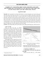
Figure 2 describes the relation between
turbine mechanical power, water How speed,
water height with gate step openning.
D|, : inertia moment of the unit including a
rotating parts
I
T,n : mechanical time constant of the unit (s).
III. SYNTHESIS OF A GOVERNOR
CONTROLLER
•
The speed governing and the powe
governing are analyzed separately in order ti
illustrate the procedure for calculating thi
controller parameters in different modes o
operation. The practical considerations cm
should take into account are the different modei
of operation of the turbine governing systen
and combined speed and power governing,
,
I
Figure 2. Gate step openning
2.3 Power-Unit Rotor Dynamics Model
3.1 Speed Governing
Dynamics of a power unit in the turbine
governing systems, in most of the cases, can be
described by using only inertia moment of the
power unit. Using Newton's second law where
torques are expressed as powers divided by the
rotation speed, one can derive the following
The control structure of speed governing
is show on Figure 3
..iS)-
Afi),,
1
AP-AP,
Ts + D,
(11)
Fig 3. Speed governing system
PL: mechanical power on the turbine shaft (per
unit);
In [5], the linearized model of th(
hydraulic turbine is
P: base power (w);
b^^-b^J^^s
0)^ : angular velocity of the unit (in rad/s);
Gra{s) = -
\+b,,rs
With the closed loop function:
GAs)--
:y+(7;+6„7;,)5-+rxAi^'
^23^, + ^ton^' + AoP2^' +
AonS^-*-bnTJJ,y
(12)
With
(13)
2 = h^Kj + D„/„ -I- r„ - b^jx^ + b,,D;r^^. - b,j„ K,,
(14)
3 = TJ„, - 6.,r., K, - b,„TX. + 6,, ?:, (Z)/„ + r„,)
(15)
= D-b„
(16)
(17)
A^rco
^A"TCO
T^P CHI KHOA HQC & CONG NGHE CAC TRUONG D
2A,Hf„
K.,=-
—(PU...1 + Pu,., + A.„. + Pu,^ + Pu.,1 + Pu..«. + A„„9)
2A,H,
(19)
With
A,™i - 'JHrc«P,PiP;Pj..
Go - PiPlP-.P^'l.u L - H,„(p,p,p,
+ p,p,/7j + P I P J P J + P2/),p,)
Pl„l,M=-^ylHrc„PP2P,P,qMT,'GiTJ,„
PM,3=PIP2P,P,'!IIT'TJ.,G„
Pu,.s = -3//rro?:, G„'£>„ + //^„7;, TJ.,G„(p,p, + p,p, + p,p, + /),p, + p,p, + P J P J
Pu.-,=D,.H'.^,(-2H^J,
+2q,JJ-ZD„Hi„TA
Pu., =-'iD„q^^H'jiJ„ G„ + Hi.l,T;G-TJ,„(p,p,p, + p,p,p, + A A A + A P I A )
PuM= HTcJ'«GJX,(p,p,p,q^,+
p,p,p.,q^^+ p,p,p,q„^+ p,p,p,q„^+ p,p,p,T„.Gi) (20)
3.2 Synthesis of power governing
In which :
The block diagram of the power
controlled system is shown in Fig. 4.
Bs : numerator of the controlled system transfer
function.
As : denominator of the controlled system
transfer function.
Ys : numerator of the controller transfer
fiinction R.
Xs : denominator of the controller transfer
function R.
Fig 4. Power governing system
The transfer ftinction describing the
change of the unit power in respect to the
reference power is given in
P..
AX^+BX
(21)
Kpp: feedforward gain.
The controller will be designed using the
pole placement method, with the PI controller
K
in form:
R = K„
We would come to the transfer funtion
P^f " b,,TJ,y
K
(22)
-)-(6,,7; + T„- TJ^,,,Kp)s- + ib,,^K^, +1 -TJ,.,,K,)s + b,..K,
It can be seen that by designing
=—K- it is possible to compensate for
one of the zeros. With the assumptions of
turbine operating point hrc =H[co, nominal
Go, The controller
speed £y V = 1,
parameters as ftinctions can be calculated as
follows
i^ _
^
"•/> ~ AjUi
(_Aipi2
^
T^ PIJ'P, '^P'PI". '^P'TPI '
TAP Clll KHOA HQC & C6NG NGHf, CAC TRUttNG D
PPlP,TJ. G„
2A,H'
(23)
Trong do :
/v„ =2w„,(ftp,+/),/), + /),f.,)7;,7;,q, (24)
p^r,:=i"^'PihPjJ:.G;,
(25)
A,H =-p,P:P,T,V:(^,i--'2q,, + 2 q „ / 7 ^ ) (2(,)
TV. SIMULATION
4.1 Speed governing simulation
Simulation parameters are obtained from
the Ryninh hydro power unit with: nominal
power P|,= 1.2 (MW), H= 76 (m), penstock:
DTC=. 1.3 (ml, f= 50 (Hz), Tw= 0.87 (s), y,,"
0.97 (u). qNi= 0.09 (mVs), T,„= 5 (s), K,= 5,
T,= 0.02.
The desired poles are chosen as:
p, = -0,1 ; p: = -0,l;
pj=-0,14.
The results of the model simulation usin|
nonlinear model and responses of the rea
system for the unit with the implementet
controller are shown in Fig 5. In these figures
compensation by the speed controller for th(
load step change is given.
The simulation was conducted with step
changes of 10% and al the time t = 660s, the
load was suddenly rejected to test for Uirbine
over speed. The simulated results are shown ir
figure 6. It can be seen that the oveshool is less
than \% and in he suddenly rejected load case,
the turbine over speed is about 30%, which is
much less than the 50% allowable standanj.
4.2. Power governing simulation
Similar simulation was also conducted
for power govering. With the desired poles are
chosen as pi=-1,2 vi p:= - 1,2 and the
controller parameters K.p=0,08;
Ki= 0,1;
Kpp= -0,08. The simulated results are shown in
Figure 7
It then calculates Kp= 1,82;K,=0,08; Kj= 7,51
according to (17)-(19).
oirixt'-ãã.ããô
hi /
L
Fig 7. Step response in power governing.
Fig 5. Step response in position control.
Fig 6. Pisewise step
governing.
response
in speed
\ . IMPLEMENTATION EXAMPLES
The experiments given in this section
were conducted throughout the whole operating
range of the turbines. The hardware, which
integrates the main controller and the Human
Machine Interface (HMI), is applied to develop
the dynamic real-time system. The hardware
consists of a 16-bit CPU of Microchip DsPIC
33F, a 5.7 inch QVCA (320*240 pixels), 256
KB SRAM, a RS232 interface, a CAN interface
(electrically isolated, network capable), a 24V
DC power supply, 10 digital input channels (the
former 4 channels can be used for frequency
measurement, 8 digital output channels.
TAP CHi KHOA HOC & CONG NGHE CAC T R U ' 6 N G DAI HQC KV THUAT * SO 86-2012
Additionally, 4 channels analog input (12
bits resolution, 0-lOV) is used to measure the
digital control signal of the hydraulic governor,
the main servomotor stroke and the wicket gate
opening. The hardware configuration is shown
in the figure 8.
T, '^'wM'^^'&^!fV^''^^
=f
/•Vl,' III I'hr rcil KcihT.iKir's
frcijii.'iin
\ I. ( ()N( l.l SION
llw :iu(li..i- pr
no^cl g . u c n u . r c m
li_\drockxhK piv.xcr ]
ted III liiis p;ipcr ihc
sirale"V lor ;i small
Tl
Fig S. The /-Lv/ nine digiia!
conlniller
Turbine go\criior was iinplcmcnicd in
the R>nmh hydropower. on I 2 MW Fram-i.s
turbines. The responses of the real s\slem with
the implemented controller are shown in l-igs.
9-10. The experiments are gi\ en tor power
demand change. For simplicit\ of controller
implementation, fixed parameters were used,
Howexer. the slahiht\- and the d_\namical
belia\ ior in the whole operaling range were
checked experimentali\ and for the particular
planl case, satisfaciory results were achieved.
Due to space limit, not all measured results are
given here.
^^JBHM*^*iiMt**' W' in imi4*'4 ft^iiit>.rt(i|J
Fig i:
The IIMI nilertaec (>t liirhinc
i:,'nvn!or
I he
author
has
verified
control
perRimianee of the luwel governor eiiuipmenl
b\ the sinuikition tool, and also conllnned the
effecli\eiiess of the planl simulaiioii model
thought experiments.
Fig 9. Field tests of the turbine
controller
In this brief, it has been shown that PID
control can achieve a substantial improvement
in tracking a power target. An advantage of the
T^P CHi KHOA HQC & C 6 N G NCHf CAC TRU'bNG D^l HQC KY THUAT * S6 86 PID controller is that it is relatively easy to
implement and commission. This makes testing
easy and relatively safe, wh.ch ,s miportant
when there are severe mancia consequences if
, . . , . , , , . , . .
. ^
the planl should hiil durmg operation.
Acknowlegement
.^^ ^^^^^^ gratefully ac
edge the
^^.^
^^ ^
|.^^^ ^ j C / ^ , , , ID-DTDU.
xi • i r* • . u- u ô^kUfi ãã. i i rarrv nut
National Project which enabled u; ' ' carry out
...
.
REFERENCES
i
1. Jiang Chang. Zhihuai Xiao, Shu qingwnag. "Neural network predict control for the hydro turbine
generator set,". The second international conference on machine learning and cybernetics
(1CMLC2003). 2003, pp.2-5.
2. GUI Xiao-yang, MEI Sheng-wei, LIU Feng and LU Qiang, "Adaptive Nonlinear Control for
Hydraulic Turbine Governor," IEEE Trans. Proceeding of the CSEE. Vol.26, No.8, pp.66-7I, Apr.
2006.
3. Har\'ey, A., Brown, A., Helliarachi, P. and Inversin, A., Micro Hydel Design Manual, A Guide to
Small Scale Water Power Schemes, Iniermediate Technology Publications, 1993.
4. Kundur, P. Power system stability and Control Tala-McGraw Hill Co. 1221, Avenue of the
Americas, New York, NY. 1994.
5. Working Group on Prime Movers, Hydraulic turbine and turbine control models for system
dynamic studies, IEEE Transaction on Power System, 7, 1992, pp. 167-179.
6. W. Grega, "Hardware-in-the-loop simulation and its application in control education", 29th
ASEE/IEEE Frontiers in Education Conference. Session 12b6, pp. 7 12. November, 1999.
Author's address: Nguyen Hong Quang -Tel: 0912.068.608, Email; quangnh(5^mail.hut.edu.vn
Bp mon T^r dong hoa xi nghiep cong nghiep - Vi?n Dien
Trudng Dai hpc Bach khoa Ha Npi
So I - Dai C6 Viet - Hai Ba Trimg - Ha Npi.