A 2.4 to 3 Gb/s reference less half rate CDR with adaptive equalizer in wireline receivers
Bạn đang xem bản rút gọn của tài liệu. Xem và tải ngay bản đầy đủ của tài liệu tại đây (1.33 MB, 9 trang )
TNU Journal of Science and Technology
227(15): 84 - 92
A 2.4 TO 3 Gb/s REFERENCE-LESS HALF-RATE CDR
WITH ADAPTIVE EQUALIZER IN WIRELINE RECEIVERS
Nguyen Thi Thao1, Le Thi Luan1, Nguyen Thanh2, Mai Thanh Hai2, Nguyen Le Van2,
Le Tien Hung2, Nguyen Huu Tho2*
1
Academy of Military Science and Technology, 2Le Quy Don Technical University
ARTICLE INFO
ABSTRACT
Received:
17/8/2022 This paper presents a 2.4 to 3 Gb/s reference-less half-rate clock and data
recovery (CDR) with combined adaptive equalizer (EQ) in wireline
Revised:
16/9/2022 receiver. A wide-band receiver based on this structure is appropriate for
Published:
16/9/2022 a high-speed wireline systems. The broadband CDR achieves by using a
two-step frequency tracking scheme: coarse and fine. In addition, in this
work the coarse/fine frequency acquisition processes operate
KEYWORDS
simultaneously to obtain a fast frequency acquisition time. The adative
High-speed wireline receiver
continuous-time linear equalizer (CTLE) based on sampled data edge
counting is employed to achieve both short adaptive time and low power
Reference-less clock
dissipation. A combination of EQ and CDR is proposed to achieve fast
Clock and Data Recovery
data recovery and processing times for the receiver. The proposed
Adaptive Equalizer
receiver is implemented in 180 nm CMOS process. It has the adaptive
Short frequency acquisition
time of 4.4 µs and a frequency acquisition time of 3 µs for the tracking
time
range from minimum frequency to maximum frequency of the voltage
controlled oscillator (VCO). The receiver circuit has shown peak-to-peak
jitter in recovered clock and data of 40 ps and 70 ps, respectively, with 3
Gb/s input data, whereas it consumes 42.7 mW at a 1.8-V supply.
THIẾT KẾ MẠCH CDR BÁN TỐC KHÔNG SỬ DỤNG TẦN SỐ THAM CHIẾU
TỪ 2.4 ĐẾN 3 Gb/s KẾT HỢP VỚI MẠCH SAN BẰNG THÍCH NGHI
TRONG MÁY THU CĨ DÂY
Nguyễn Thị Thảo1, Lê Thị Luận1, Nguyễn Thành2, Mai Thanh Hải2, Nguyễn Lê Vân2,
Lê Tiến Hưng2, Nguyễn Hữu Thọ2*
1
Viện Khoa học và Công nghệ Quân sự, 2Học viện Kỹ thuật Qn sự
THƠNG TIN BÀI BÁO
TĨM TẮT
Ngày nhận bài:
17/8/2022 Bài báo này trình bày về mạch khơi phục dữ liệu và xung đồng hồ (CDR)
Ngày hồn thiện:
16/9/2022 san bằng thích nghi trong máy thu có dây. Máy thu băng rộng dựa trên cấu
16/9/2022 trúc này thích hợp cho các hệ thống có dây tốc độ cao. Mạch CDR băng rộng
Ngày đăng:
bán tốc không sử dụng tần số tham chiếu từ 2,4 đến 3 Gb/s kết hợp với mạch
đạt được bằng cách sử dụng sơ đồ bám tần số theo hai bước: thơ và tinh.
Ngồi ra, trong nghiên cứu này, q trình bám tần số thơ và tinh hoạt động
TỪ KHĨA
đồng thời để đạt được thời gian bám tần số ngắn. Mạch san bằng tuyến tính
Máy thu có dây tốc độ cao
thời gian liên tục (CTLE) dựa trên bộ đếm được sử dụng để đạt được đồng
Không sử dụng tần số tham thời cả thời gian thích nghi ngắn và cơng suất tiêu thụ thấp. Sự kết hợp giữa
CDR và EQ được đề xuất để đạt được thời gian xử lý và khôi phục dữ liệu
chiếu
Mạch khôi phục dữ liệu và nhanh cho máy thu. Máy thu đề xuất được thiết kế trên cơng nghệ CMOS
180 nm. Mạch có thời gian thích nghi là 4,4 µs và thời gian bám tần số là 3
xung đồng hồ
µs với khoảng bám từ tần số nhỏ nhất đến tần số lớn nhất của bộ dao động
Mạch san bằng thích nghi
điều khiển bằng điện áp (VCO). Máy thu có jitter của xung đồng hồ và dữ
Thời gian bám tần số ngắn
liệu khôi phục lần lượt là 40 ps và 70 ps với dữ liệu đầu vào là 3 Gb/s. Mạch
tiêu thụ công suất 42,7 mW với nguồn cung cấp 1,8 V.
DOI: />*
Corresponding author. Email:
84
Email:
TNU Journal of Science and Technology
227(15): 84 - 92
1. Introduction
In serial data communication systems, a clock and data recovery (CDR) circuit is placed at the
receiver side to recover the data from an incoming data stream and should run at the high rate.
CDRs can be classified as referenced or reference-less. The first method uses an external reference
clock for frequency acquisition. This method is simple but it increases the design cost. The second
method extracts directly the clock from the input data stream without an external reference clock.
Thereby, it can be used for many different applications. Recently, the reference-less CDRs are
widely adopted in various applications [1] – [5]. However, frequency acquisition methods in [1], [2]
use a unilateral frequency detector (FD), in which, [1] and [2] suggested initiating the operation of
voltage controlled oscillator (VCO) from the minimum and maximum frequency for frequency
tracking process, respectively. This leads to a longer frequency acquisition time. To overcome
limitation of the unilateral FD, the several bidirectional FDs in the CDR designs were proposed [3]
- [5]. A uniform probability of 0.25 for all four possible transitions of the random data patterns was
assumed in [3]. Consequence, the CDR performance strongly depended on transition density of the
input data. In [4], the frequency acquisition process always starts from the middle band of the VCO,
resulting in longer frequency acquisition time of the CDR circuit. The counter-based FD [5] is
employed to obtain unrestricted frequency acquisition in reference-less CDR but its performance
also could be degraded by the inter-symbol interference (ISI).
The demand for a higher data bandwidth in serial data communication keeps increasing with
respect to the development of CMOS technology performance. To meet this requirement while
ensuring low bit error rate (BER), the equalizers (EQ) at the receiver side are used because of the
poor channel conditions at higher data rates. However, because channel conditions are not always
known in advance for data transmission, an EQ circuit with a pre-designed channel loss
compensation factor does not achieve optimal equalization performance. Thus, adaptive EQ
circuits become more relevant in practice and more attractive in research [6] – [10]. In [6], the
spectrum balancing technique has been used for continuous-time linear equalizer (CTLE)
adaptation process. However, it suffers from process, voltage, and temperature (PVT) variations.
The adaptation method based on the slope-detection for the CTLE is presented in [7] but it
requires large power dissipation. Design [8] illustrates the adaptive equalization method based on
an eye-opening monitor. However, the quality of the EQ is strongly dependent on the transfer
density of the input data. To overcome these drawbacks, counter-based adaptive techniques are
proposed in [9], [10]. However, these EQs require an external reference clock to generate the
time windows and to sample the data.
In high-speed wireline receivers, a CDR circuit is combined with an EQ to achieve low BER
[11] – [15]. However, the receivers in [11] – [13] employed an external reference clock for
frequency acquisition process. The receiver architectures in [14], [15] is reference-less but they
had a long frequency tracking time, 680 µs in [15] and 5.5 ms in [14]. Moreover, the equalizers
in [14], [15] do not have the ability to adapt to different channel conditions.
This paper proposes a receiver architecture including an adaptive EQ and a reference-less CDR.
By using an adaptive EQ based on counter [16] and a CDR with two-step frequency tracking
scheme [17], the proposed receiver achieves short adaptation and frequency tracking time, and a
reasonable power consumption, simultaneously. This paper is organized as follows. Section 2
introduces the architecture of the proposed receiver. Next, in Section 3, the principle of the adaptive
equalization and frequency detection in wireline receiver is described in detail. Section 4 shows the
experimental results on 180 nm CMOS process followed by conclusions in Section 5.
2. Receiver Architecture
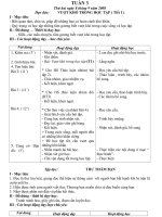
Figure 1 illustrates the block diagram of the proposed half-rate wireline receiver circuit. It
consists of an adaptive EQ, a current mode logic (CML)-to-CMOS circuit and a reference-less
85
Email:
227(15): 84 - 92
TNU Journal of Science and Technology
CDR. After the adaptive EQ, the data is fed into the CML-TO-CMOS circuit to convert to fullswing data for the CDR. The CDR includes a half-rate bang-bang phase detector in current-mode
logic for high speed, a wide-band frequency detector, a VCO and two charge pump circuits. In
this dual-loop CDR circuit, both frequency detector and phase detector use the same loop filter
via the connection of switches S1 and S2, respectively. Switch S1 selects the frequency locked
loop and switch S2 selects the phase locked loop. The FD comprises a coarse FD, a fine FD and a
frequency lock detector. A decision circuit is utilized to recover data.
Decision
Circuit
Dinb
CML to
CMOS
Adaptive
Equalizer
EQ
Recovered Data
VCO
UPPD
Phase
Detector
DNPD
Charge
Pump
S2
VC
PD
R1
UPFD
Frequency DNFD
Detector
Charge
Pump
C2
(1.2 ÷ 1.5) GHz
S1
C1
FD
Loop
Filter
EQ = FD
Recovered Clock
Din
CKI, CKQ
Figure 1. The block diagram of proposed wireline receiver
VC
Locked Frequency
1
1
Frequency Locked Process
2
Adaptive Equalization Process
3
Phase Locked Process
0
t
EQ
Gain
Max
3
2
Finish adaptive equalization
Min
0
t
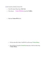
Figure 2. Operation of proposed wireline receiver
The detailed operation of the proposed receiver is shown in Figure 2. The adaptive EQ and the
reference-less CDR are combined in receiver by using three signals: EQ, FD and PD, in which
the FD and EQ signals are generated from the frequency detector circuit, and the PD signal is
created from the adaptive EQ circuit. The receiver operation is divided into three stages. In the
first stage, the switch S2 turns off (FD = 0, PD = 0) and switch S1 turns on (FD = 0, EQ = 1) to
activate the frequency acquisition process while the EQ gain of the adaptive EQ is set to a
maximum to minimize the effect of the ISI. After that, the FD circuit tracks the frequency error
between the incoming data and the output recovery clock to decrease this error. When the
frequency error is reduced to a small enough value, the FD signal is activated (FD = 1) by the
frequency lock detector to make S1 off and S2 on. The frequency locked process finishes and the
operation of the receiver turns to the second stage. At this stage, the EQ gain is reset to its
minimum value to start the adaptive equalization process. Subsequently, depending on channel
condition, the EQ gain increases to compensate the channel loss. When the adaptive equalization
process finishes, the EQ gain is fixed, the EQ triggers PD signal (PD = 1) to turn the operation of
the receiver to next stage. At the final stage, the half-rate binary PD takes over the final phase
acquisition process.
86
Email:
227(15): 84 - 92
TNU Journal of Science and Technology
3. Principle of adaptive equalization and frequency detection in wireline receiver
3.1. Adaptive equalization principle of EQ
The principle of adaptive equalization is demonstrated in Figure 3. The high-speed serial data
after passing the channel (EQIN) is sampled by a half-rate clock (CK) by a D-type Flip-Flop (DFF). Because the data is affected by ISI, the clock will sample the data at the correctly and
wrongly logical values (see Figure 3). The number of wrongly logical values is proportional to
the effect of the ISI. If the data is heavily influenced by ISI then wrongly logical values will
appear more and if the data is less affected by ISI then wrongly logical values will arise rarely
when sampling is performed. Thus, data sampling will evaluate the impact of ISI on high-speed
serial data. Based on this principle, an 8-bit counter is used to count the number of edges of the
data after sampling for adaptive equalization [16].
D-FF
EQIN
Data
COUNTER
8-bit
Channel
# Count value
CK
1
1
1
1
Data
0
1
EQIN
1
1
0
1
0
0
1
1
1
0
1
1
1
0
CK
ISI s effect
Correct
Wrong
Correct
Correct
Wrong
Correct
Wrong
Correct
Wrong
Correct
Figure 3. Adaptive equalization principle
As discussed earlier, adaptive equalization process is started by setting the minimum EQ gain
(C[3:0] = 0000) to maximize the effect of ISI. Then, the EQ gain will be gradually increased until
the wrongly logical values when sampling is minimized, the digital control code C[3:0] is fixed,
and the adaptive equalization process is terminated [16]. As a result, the impact of ISI on highspeed serial data is minimized.
Figure 4. Gain of CTLE
In this work, we propose using a CTLE to obtain both high boost gain and wide DC gain
range for ISI elimination and low power consumption, simultaneously. The CTLE structure based
on RC source-degeneration equalizer is implemented with a 2nd-order negative capacitor circuit
87
Email:
227(15): 84 - 92
TNU Journal of Science and Technology
[16]. To achieve a wide compensation range for channel loss, the three-stage CTLE is designed
with 16 possible gain values corresponding to control code C[3:0] as shown in Figure 4. The
CTLE has an adjustment range of 21.8 dB, from 3 dB to 24.8 dB.
3.2. Frequency acquisition principle of reference-less CDR
The coarse/fine frequency acquisition schemes were introduced in [1] and [2] for a wide-range
reference-less CDR. In these proposals, the coarse FD (CFD) and fine FD (FFD) operate
dependently, whereby the fine frequency acquisition loop starts just after the coarse frequency
tracking loop finishes. Consequently, the CDR has long frequency acquisition time. In this work,
the using of coarse/fine frequency acquisition scheme is proposed as well but with simultaneous
operating mechanism of the CFD and FFD in frequency tracking process to obtain shorter
frequency acquisition time [17].
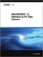
The CFD block diagram is illustrated in Figure 5. The circuit is composed of a frequency
decrement acquisition (Coarse Frequency Dn Control), a frequency increment acquisition
(Coarse Frequency Up Control), a D-FF, two OR-gates, and two multiplexers. In this circuit, the
signal DNF and UPF at the OR-gate inputs are generated by the FFD. Moreover, the Sel signal,
which is the output of a positive-edge-triggered D-FF is used to control the selection UPC/DNC
signals at the output of the CFD where UPC and DNC are outputs of the frequency increment
acquisition circuit and the frequency decrement acquisition circuit, respectively.
Based on the Sel signal, the operating principle of the proposed CFD is as follows. If the Sel
signal is low (the data is slower than the clock), the MUX1 selects UPF as the output of the CFD
(UFFD = UPF) and the MUX2 selects the output of the OR2 as the output of the CFD (DNFD =
DNC + DNF). Because the DNFD signal dominates over UPFD signal in this case, so the CFD
operates as if the frequency decrement acquisition process until arising UP C signal [18]. On the
contrary, if the signal Sel is high (the data is faster than the clock), the MUX1 selects the output
of the OR1 as the output of the CFD (UPFD = UPC + UPF) and the MUX2 selects DNF as the
output of the CFD (DNFD = DNF). When the FD closes to frequency locked state, UPC is
approximate to zero so the output of the FFD becomes the output of the CFD. The FD remains
the FFD in operation. As a result, the proposed architecture allows the CFD and the FFD to
operate simultaneously. Thereby, this architecture increases probability that the pulse UP FD and
DNFD appear to drop frequency acquisition time.
UPF
From FFD
Din
CKI
CKQ
0
Coarse
UPC
Freq.
Up Control
UPC+UPF
OR1
MUX
1
UPFD
1 S
VDD
D
Sel
Q
R
R
Din
CKI
CKQ
Coarse
Freq.
Dn Control
DNC
OR2
DNC+DNF
0 S
MUX
2
DNF
From FFD
DNFD
1
Figure 5. Two-step frequency tracking scheme of the wide-band FD
Based on the operation principle of the wide-band FD, we design the reference-less CDR with
the values of the parameters in the CDR circuit as presented in Table 1. In which, ICP-FD and ICP-PD
are charge/discharge currents for the frequency tracking loop and the phase tracking loop,
respectively. R1, C1 and C2 form 2nd-order loop filter. A ring-VCO with four-stage [18] is
employed to generate frequency from 1.2 GHz to 1.5 GHz.
88
Email:
227(15): 84 - 92
TNU Journal of Science and Technology
Table 1. Design parameter values in the CDR
C1
C2
2 nF
60 pF
R1
ICP-PD
450 Ω
20 µA
ICP-FD
FVCO
400 µA
(1.2÷1.5)GHz
4. Simulation results and discussion
A 2.4 to 3 Gb/s reference-less wireline receiver is implemented in a 180 nm CMOS process.
The proposed receiver consumes 42.7 mW from 1.8 V supply voltage without PAD while
operating at the maximum input data rate of 3 Gb/s. Table 2 presents a detailed power
breakdown. In which, the adaptive EQ consumes 29.7% of the overall power whereas the
reference-less CDR consumes 57.1% of the overall power at 3 Gb/s.
Table 2. Detailed power breakdown at 3 Gb/s
Block
EQ
CDR
Others
Total
Power
12.7 mW (29.7%)
24.4 mW (57.1%)
5.6 mW (13.2%)
42.7 mW
To verify the adaptive equalization in the proposed receiver, a channel loss model as
illustrated in Figure 6 is utilized. The channel has loss of 16.5 dB at 3 Gb/s. A 3 Gb/s PRBS-7
data is applied as input of the receiver. Figure 7 depicts simulation result of equalizer adaptation
in the receiver. At the start, the CTLE gain is established to maximum (C[3:0] = 1111). After
that, it is set to minimum (C[3:0] = 0000) to start the adaptive equalization process. When SS
signal arises the control codes C[3:0] are updated to grow the CTLE gain. The equalizer
adaptation finishes when PD signal appears. The C[3:0] is fixed as 0100 and the CTLE boosting
gain achieves 16.8 dB. The adaptive equalization time is approximately 4.4 µs.
Figure 6. Channel loss model
Figure 7. Adaptive process of the EQ in the receiver
Figure 8 presents operation of the proposed receiver in simulation. The acquisition process of
the receiver is divided by three periods. At the start, the frequency acquisition process operates
with the initial VCO frequency is 1.2 GHz. As mentioned, the EQ gain is set to maximum in this
period to minimize the ISI influence to the frequency tracking process of the receiver. Then, the
control voltage (VC) increases to grow the VCO frequency and decrease frequency error between
half the data rate and the VCO frequency. When the frequency error is small enough (the VCO
frequency closes to 1.5 GHz), the frequency lock detector toggles the signal FD to the high state
to turn-off the frequency detector. After that, the receiver transfers the loop control to the EQ
(period 2). The adaptive equalization process works to compensate the channel loss as above
mentioned. When the equalizer adaptation accomplishes, the PD signal is activated to turn the
loop control to the phase locked process (period 3). The receiver has the frequency tracking time
and the acquisition time of 3 µs and 7.4 µs, respectively.
89
Email:
227(15): 84 - 92
TNU Journal of Science and Technology
Figure 8. Operation of proposed receiver
(a)
Figure 9. Waveform of recovered
clock at 3 Gb/s input data
(b)
(c)
Figure 10. Eye diagram of data: (a) at input, (b) after equalization, (c) after recovery
Figure 9 and Figure 10 present waveforms of data and recovered clock, respectively, in which
the eye diagram of data at input, after equalization and after recovery are shown in Figure 10(a),
(b) and (c), respectively. The jitter peak-to-peak of the recovered clock is 40 ps with 3 Gb/s input
data. The eye diagram of the 3 Gb/s data is relatively closed after passing through the lossy
channel. It is open in both vertical and horizontal after equalization and recovery. The receiver
obtains jitter peak-to-peak of data after equalization and recovery of 110 ps and 70 ps,
respectively. As a result, the EQ and the reference-less CDR work well to eliminate the ISI and
fall BER. Table 3 lists a performance summary of CDR with equalizer in wireline receiver in
literature. This work has the shortest acquisition time and comparable dissipation power when
compared to [11], [14], [15]. Specifically, the proposed receiver obtains the acquisition time of
7.4 µs while reference [14] and [15] are 10100 µs and 480 µs, respectively. Moreover, in
proposed wireline receiver, compared with [14], [15], the EQ has adaptive equalization capability
and compared with [11], the CDR has reference-less architecture.
Table 3. Performance Comparison of proposed receiver
Technology
Supply (V)
Data Rate (Gb/s)
Equalizer
CDR Architecture
Acquisition Time
[(FDATA-FCLK)/FCLK]
Channel Loss (dB)
Power (mW)
[11]
(measure)
28 nm CMOS
1
6
Adaptation
Reference
N/A
27.8
31@6Gb/s
[14]
(measure)
28 nm CMOS
0.9
22.5-32
Without adaptation
Reference-less
< 10100 µs
[+14.3%]
14.8
102@32Gb/s
90
[15]
(measure)
40 nm CMOS
1.2
10.432-16
Without adaptation
Reference-less
< 480 µs
[+23.8%]
10.14
39.9@16Gb/s
This work
(Simulation)
180 nm CMOS
1.8
2.4-3
Adaptation
Reference-less
7.4 µs
[+25%]
16.5
42.7@3Gb/s
Email:
TNU Journal of Science and Technology
227(15): 84 - 92
5. Conclusion
The proposed wireline receiver is implemented in 180 nm CMOS process. The wireline
receiver has simple architecture and achieves short acquisition time. By using the digital
adaptation algorithm based on counter, the EQ obtains both the fast equalizer adaptation time and
low power consumption. A two-step frequency tracking scheme and simultaneous operation of
the CFD and FFD are employed to fall frequency acquisition time, outperforming previous
published wireline receiver. The limitation of this work is that there are no measurement results
yet and without decision feedback equalizer (DFE) in equalization process. Therefore, in future
work, we will tape out chip to get measured results and integrate the CTLE and DFE in
equalization process to further improve the ISI elimination of the wireline receiver.
REFERENCES
[1] G. Shu, W. S. Choi, S. Saxena, M. Talegaonkar, T. Anand, A. Elkholy, A. Elshazly, and P. K.
Hanumolu, “A 4-to-10.5Gb/s Continuous-Rate Digital Clock and Data Recovery with Automatic
Frequency Acquisition,” IEEE J. Solid-State Circuits, vol. 51, no. 2, pp. 428-439, Feb. 2016.
[2] J. Jin, J. Kim, H. Kim, C. Piao, J. Choi, D. Kang, and J. Chun, "A 4.0–10.0-Gb/s Referenceless CDR
with Wide-Range, Jitter-Tolerant, and Harmonic-Lock-Free Frequency Acquisition Technique," IEEE
44th European Solid State Circuits Conference (ESSCIRC), Germany, Sep. 2018.
[3] R. Inti, W. Yin, A. Elshazly, N. Sasidhar, and P. K. Hanumolu, “A 0.5-to-2.5 Gb/s Reference-Less
Half-Rate Digital CDR With Unlimited Frequency Acquisition Range and Improved Input DutyCycle Error Tolerance,” IEEE J. Solid-State Circuits, vol. 46, no. 12, pp. 3150-3162, Dec. 2011.
[4] J. Jin, X. Jin, J. Jung, K. Kwon, J. Kim, and J. Chun, “A 0.75–3.0-Gb/s Dual-Mode TemperatureTolerant Referenceless CDR With a Deadzone Compensated Frequency Detector,” IEEE J. Solid-State
Circuits, vol. 53, no. 10, pp. 2994-3003, Oct. 2018.
[5] K. Sohn, T. An, Y. Moon, and J. Kang, “A 0.42 - 3.45 Gb/s Referenceless Clock and Data Recovery
Circuit with Counter-based Unrestricted Frequency Acquisition,” IEEE Trans. Circuits and Systems-II,
Express Briefs, vol. 67, no. 6, pp. 974-978, Jun. 2020.
[6] B. Nakhkoob and M. M. Hella, "A 4.7-Gb/s Reconfigurable CMOS Imaging Optical Receiver Utilizing
Adaptive Spectrum Balancing Equalizer," IEEE Transactions on Circuits and Systems I: Regular
Papers, vol. 64, no. 1, pp. 182-194, 2016.
[7] D. Lee, J. Han, G. Han, and S. M. Park, "An 8.5-Gb/s fully integrated CMOS optoelectronic receiver
using slope-detection adaptive equalizer," IEEE Journal of Solid-State Circuits, vol. 45, no. 12, pp.
2861-2873, 2010.
[8] H. Won, J. Y. Lee, T. Yoon, K. Han, S. Lee, J. Park, and H. Bae, "A 28-Gb/s receiver with selfcontained adaptive equalization and sampling point control using stochastic sigma-tracking eyeopening monitor," IEEE Transactions on Circuits and Systems I: Regular Papers, vol. 64, no. 3, pp.
664-674, 2018.
[9] Y. Lin, C. Huang, J. M. Lee, C. Chang, and S. Liu, “A 5–20 Gb/s power scalable adaptive linear
equalizer using edge counting,” 2014 IEEE Asian Solid-State Circuits Conference (A-SSCC), 2014, pp.
273-276.
[10] Y. Choi, Y. Lee, H. Park, J. Choi, J. Sim, Y. Kwon, and C. Kim "A 0.99-pJ/b 15-Gb/s Counter-Based
Adaptive Equalizer Using Single Comparator in 28-nm CMOS,” IEEE Trans. Circuits and Systems-II,
Express Briefs, vol. 68, no. 10, pp. 3189-3193, Oct. 2021.
[11] H. Kim, and C. Joo, “A 6-Gb/s Wireline Receiver With Intrapair Skew Compensation and Three-Tap
Decision-Feedback Equalizer in 28-nm CMOS,” IEEE Transactions on Very Large Scale Integration
(VLSI) Systems, vol. 28, no. 5, pp. 1107-1117, May 2020.
[12] G. Mandal, S. Rajan, S. K . Ghosh, S. Hazra, R. Molthati, P. R. Bhuta, S. K. Reddy, V. G. Jawarlal,
and K. Pandya, “A 2.68mW/Gbps, 1.62-8.1Gb/s Receiver for Embedded DisplayPort Version1.4b to
Support 14dB Channel Loss,” IEEE Asian Solid-State Circuits Conference, Japan, Nov. 2020.
[13] M. Choi, H. Ko, J. Oh, H. Joo, K. Lee, and D. Jeong, “A 0.1-pJ/b/dB 28-Gb/s Maximum-Eye
Tracking, Weight-Adjusting MM CDR and Adaptive DFE with Single Shared Error Sampler,” IEEE
Symposium on VLSI Circuits, Honolulu, HI, USA, June 2020.
91
Email:
TNU Journal of Science and Technology
227(15): 84 - 92
[14] W. Rahman, D. Yoo, J. Liang, A. Sheikholeslami, H. Tamura, T. Shibasaki, and H. Yamaguchi, “A
22.5-to-32-Gb/s 3.2-pJ/b referenceless baud-rate digital CDR with DFE and CTLE in 28-nm CMOS,”
IEEE J. Solid-State Circuits, vol. 52, no. 12, pp. 3517–3531, Dec. 2017.
[15] W. Chen, Y. Yao, and S. Liu, “A 10.4–16-Gb/s Reference-Less Baud-Rate Digital CDR With OneTap DFE Using a Wide-Range FD,” IEEE Transactions on Circuits and Systems I: Regular Papers,
vol. 68, no. 11, pp. 4566-4575, Nov. 2021.
[16] M. H. Pham, H. T. Nguyen, and T. Q. Nguyen, “An Adaptive Continuous-Time Linear Equalizer
Using Sampled Data Edge Counting,” 19th International Symposium on Communications and
Information Technologies (ISCIT), Ho Chi Minh City, Vietnam, Sep. 2019.
[17] H. T. Nguyen, H. Lee, T. J. An, and J. K. Kang, “A 0.32 - 2.7 Gb/s Reference-less Continuous-rate
Clock and Data Recovery Circuit with Unrestricted and Fast Frequency Acquisition,” IEEE Trans.
Circuits and Systems-II, Express Briefs, vol. 68, no. 7, pp. 2347-2351, July 2021.
[18] H. T. Nguyen, M. H. Pham, T. L. Le, T. T. Le, and T. Q. Nguyen, “Designing wide-band referenceless continuous-rate clock and data recovery circuit using 180 nm CMOS process,” Journal of Military
Science and Technology, vol. 63, pp. 46-58, Oct. 2019.
92
Email:

![TỔNG HỢP MỘT SỐ N-ARYL/HETARYL 2-{4-AMINO-5-[(4,6-DIMETHYL PYRYMIDIN-2-YLTHIO)METHYL]-4H-1,2,4-TRIAZOL-3-YLTHIO}ACETAMIDE](https://media.store123doc.com/images/document/14/y/vn/medium_Yr8VohbjEU.jpg)