Preliminary analysis of an integral Small Modular Reactor operating in a submerged containment
Bạn đang xem bản rút gọn của tài liệu. Xem và tải ngay bản đầy đủ của tài liệu tại đây (2.63 MB, 10 trang )
Progress in Nuclear Energy 107 (2018) 90–99
Contents lists available at ScienceDirect
Progress in Nuclear Energy
journal homepage: www.elsevier.com/locate/pnucene
Preliminary analysis of an integral Small Modular Reactor operating in a
submerged containment
T
Marco Santinello∗, Marco Ricotti
Politecnico di Milano, Dept. of Energy - CeSNEF-Nuclear Engineering Division, Via La Masa 34, 20156 Milano, Italy
A R T I C LE I N FO
A B S T R A C T
Keywords:
Submerged SMR
Integral PWR
Passive safety
This work addresses the conceptual design of a submerged nuclear power plant, where a horizontal cylindrical
hull, placed on the floor of a sea or an artificial lake, hosts an integral pressurized Small Modular Reactor (SMR).
A scaled version of the International Reactor Innovative and Secure (IRIS) that matches the requirements of the
submerged containment is here proposed, providing a preliminary sizing of the primary components. Based on
the presence of a large water reservoir (sea or lake) acting as a permanent heat sink, a basic fully passive safety
strategy has been developed and its principles have been investigated, by means of the numerical simulation of a
Station Black-Out (SBO) scenario. The outcomes show that natural circulation flows in the primary circuit and in
the Emergency Heat Removal System (EHRS) can provide a very effective heat transfer capability from the fuel
rods to the external water. The submerged reactor design owns very interesting safety features, which inherently
prevent from the Fukushima-like scenarios, i.e. Loss Of Offsite Power (LOOP) and a Loss of Ultimate Heat Sink
(LUHS), thus representing a noticeable improvement for a next generation nuclear reactor. However, some
critical issues for the deployment of such a concept are also identified and briefly discussed.
1. Introduction
Emergency cooling during Fukushima Daiichi nuclear accident
failed because of the loss of on-site/off-site electrical power and the
consequent lack of a heat sink. The accident has emphasized that current nuclear power plants may show strong difficulties in facing prolonged Station Black-Out (SBO) scenarios. The response of nuclear industry to this event included a renovated attention to the development
of passive safety systems for new designs (International Atomic Energy
Agency, 2016a). Passive systems own the potential to improve the
safety of nuclear power plants, as well as to simplify the layout and to
reduce the costs. After Fukushima, guaranteeing an adequate core
cooling through natural circulation for a very long grace period,
without electrical input or human intervention, has become an important feature for the safety strategy of some Gen III + designs. During
the last three decades, those requirements have stimulated large efforts
among researchers in nuclear thermal-hydraulics, aimed at understanding the physics and predicting the transient evolution of natural
circulation and multiphase flow. These efforts are currently going on to
support the design of safer, cheaper and sustainable nuclear reactors.
Submerged Small Modular Reactors (SMRs) can potentially address this
challenge. Nowadays they are mainly at conceptual design level, but
their development could provide a great technological advancement in
∗
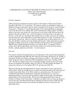
the nuclear industry. Those nuclear reactors operate in a containment
moored on the floor of a sea or an artificial lake (Fig. 1) and the power
generated is transferred to the land. This concept offers unique safety
features in terms of enhanced protection towards Fukushima-like accident scenarios, i.e., Loss Of Off-site Power (LOOP) and Loss of Ultimate Heat Sink (LUHS), as well as other critical scenarios, including
Loss Of Coolant Accident (LOCA), and external events, e.g., flooding,
tsunami and malevolent human actions.
In the framework of the development of innovative reactor designs,
the submerged SMR concept has obtained a certain attention in recent
years. Early projects were presented by Electric Boat (General Dynamics
Electric Boat Division, 1971) and Herring (1993) in the 1970's and
1990's respectively. The recent progress in subsea oil&gas technologies,
in submarine cables for offshore renewables and in shipbuilding techniques, makes offshore power reactors more feasible today than before,
with an increasing interest towards this option (Buongiorno et al.,
2016).
In 2014, the French company DCNS (now Naval Group) presented
the Flexblue concept (Haratyk et al., 2014), a subsea and fully transportable modular power unit that supplies 160 MWel to the grid via
submarine cables. Flexblue adopted pressurized water reactor technology and the projects was aimed at implementing several enhanced
passive safety features, to exploit the seawater as a permanent heat sink
Corresponding author
E-mail addresses: (M. Santinello), (M. Ricotti).
/>Received 28 December 2017; Received in revised form 11 April 2018; Accepted 19 April 2018
Available online 30 April 2018
0149-1970/ © 2018 The Authors. Published by Elsevier Ltd. This is an open access article under the CC BY-NC-ND license ( />
Progress in Nuclear Energy 107 (2018) 90–99
M. Santinello, M. Ricotti
2. Revisited reactor layout: IRIS-160
2.1. Overview
Scaling the IRIS design is not a new operation: in 2009 Petrovic
et al. (2009) proposed the concept of IRIS-50, a reduced power (50
MWel) version of the reference IRIS design, conceived to better address
cogeneration purposes and to supply electricity to remote or isolated
areas. However, in the present case the constraints and the requirements are considerably different. The primary limitation for the design
of a submerged SMR is given by the diameter of the horizontal cylindrical containment. Based on construction capacity and feasibility
end economics considerations, DCNS proposed a 14-m diameter hull
(Haratyk et al., 2014) for the Flexblue case. That value is assumed as
reference for this work. Another constraint is the heat transfer capability of the hull during emergency operation, which identifies the
power output of the reactor. Santinello et al. (2017a) investigated that
capability with a CFD study and found that the decay power of a 500
MWth (roughly 160 MWel) reactor could be rejected through the containment. Thus, that value is assumed for a scaled IRIS-160 version.
Reactor scaling mainly consists of revisiting the design of primary
components, i.e. reactor core, control rods driving mechanism, steam
generator, primary pumps and pressurizer.
Fig. 1. Concept of a submerged SMR
and ensure an unlimited grace period in case of accident. In addition,
Flexblue can offer other advantages in terms of manufacturing and
possibility to reach isolated sites. Some analyses about core design and
safety strategy of Flexblue are available in open literature (Ingremeau
and Cordiez, 2015) (Santinello et al., 2017a) (Haratyk and Gourmel,
2015) (Gourmel et al., 2016), but important issues concerning the reactor design and safety systems are still under development. In particular, although pressurized water is undoubtedly the most reliable
technology for such a concept, Flexblue still does not present a final
reactor layout. Two solutions were under consideration, but a thorough
investigation about their capability to achieve design and safety targets
has not yet been addressed. As a first option, DCNS used a VVER-type
design for preliminary safety analyses (Haratyk and Gourmel, 2015)
(Gourmel et al., 2016). Thanks to the horizontal U-tube Steam Generator (SG), the total height of the reactor does not exceed the diameter
of Flexblue hull (14 m), but such solution does not provide compactness
to the primary system. Moreover, the horizontal layout of the SGs does
not facilitate a natural circulation regime during emergency cooling. A
second option proposed by CEA is the SCOR-F concept (NUSMoR,
2014), a reduced power version of the 600 MWel Simple COmpact
Reactor (SCOR). It consists of a pressurized reactor with a vertical Utube steam generator placed right on top of the core. This layout seems
not suitable to minimize the global height of the reactor and to fit the
containment. A work by Shirvan et al. (2016) examined five nuclear
technologies in relation to their adaptability for an offshore underwater
SMR: Lead-Bismuth Fast Reactor (LBFR), Organic Cooled Reactor
(OCR), Superheated Water Reactor (SWR), Boiling Water Reactor
(BWR) and integral PWR. They concluded that all these technologies
are good for a fully passive safety strategy. However, LBFR and OCR,
which are identified as the most suitable technologies, can rely on a
very little experience in civil nuclear industry, therefore achieving a
complete reactor design and meeting the requirement of safety authorities would be very difficult and not feasible in the short-medium term.
The present work introduces the concept of an integral PWR (iPWR)
SMR, suitable to operate in a submerged containment and based on a
scaled version of the International Reactor Innovative and Secure (IRIS)
(Carelli et al., 2004) (Petrovic et al., 2012). IRIS is an integral, modular,
medium size (335 MWel) PWR, based on passive safety systems and a
pressure suppression, steel containment. The new proposal is aimed at
obtaining a reactor layout able to satisfy design and layout constraints
as well as safety requirements. The primary components have been
revisited in order to reduce the electrical output to 160 MWel and the
reactor height below 14 m (Section 2), providing a preliminary sizing
and thus letting define a basic safety strategy (Section 3). Then, the
resulting preliminary design has been tested in a numerical simulation
of a SBO scenario (Section 4), where the secondary side of the steam
generator is connected to an emergency condenser immersed in the
external seawater. The simulations put on evidence the potentiality that
such conceptual design can offer in term of enhanced safety features.
However, many challenges about the deployment of a submerged SMR
still remain open: these are identified and briefly discussed in Section 5.
2.2. Reactor core
Reactor core design considers a standard PWR fuel assembly as
adopted in IRIS: a configuration made of 89 fuel assemblies with 264
fuel rods in a 17 × 17 square array. The resulting diameter of the core
is around 2.75 m. The active height of the fuel elements has been scaled
down to reduce the power output: the active height of IRIS-160 fuel
element must be roughly halved with respect to the 4.20 m fuel assembly height adopted in IRIS. Among the current or proposed offer of
fuel elements, some products seem to be suitable for the purpose, e.g.
Framatome, Lo-Lopar, M-Power and Westinghouse SMR, all with active
height around 2.5 m (Nuclear Engineering International (NEI), 2014).
The active height of NuScale and Smart reactors is 2 m and CAREM-25
adopts 1.4 m height elements (International Atomic Energy Agency,
2016b), although these reactors are designed with power output
smaller than IRIS-160. In principle, a 2-m value for the fuel assembly
active height can be reasonably assumed. Considering gas plenum and
core support plates, the overall height of IRIS-160 core would be in the
range of 3.00–3.20 m. Albeit neutronic verification must be performed
to assess the of such a core, the solution seems feasible.
2.3. Control rods driving mechanism
An integral reactor allows placing the Control Rods Driving
Mechanism (CRDM) inside the Reactor Pressure Vessel (RPV). This
carries two advantages: (i) the rod ejection accident is eliminated by
design, because there is no differential pressure to drive out the CRDM
extension shafts; (ii) there are no nozzle penetrations on the upper head
of the RPV. In IRIS design, the CRDM was placed above the core and
actuated with electromagnetic or hydraulic mechanism. For IRIS-160, a
similar approach is maintained. The height of the CRDM is roughly
twice the total length of the fuel assembly, to host the withdrawn
control rods and the drive line, plus the height of the handling mechanism. The overall height can be estimated between 5.5 and 6.0 m.
2.4. Steam generator
The Steam Generator (SG) design for IRIS-160 has undergone large
modifications with respect to the IRIS original design. In IRIS, eight
helical coil SG modules were placed around the barrel, with module
diameter equal to 1.5 m. Such solution is not feasible for IRIS-160: due
to the reactor size reduction, for economic reasons it is desirable to
91
Progress in Nuclear Energy 107 (2018) 90–99
M. Santinello, M. Ricotti
rate or (b) for the outlet specific enthalpy, respectively. The advantage
of choice (a) is a dramatic reduction of pressure losses on the primary
side due to the decrease of the total mass flow rate, while choice (b)
represents the best solution to maximize the temperature difference
between primary and secondary fluid and therefore to enhance the heat
transfer process. Both alternatives are analyzed. As far as secondary
side flow rate is concerned, it has been reduced in order to obtain superheated steam at outlet, with the same specific enthalpy of the
standard IRIS. The same primary and secondary operating pressures of
IRIS, i.e. 15.5 and 6.2 MPa respectively, have been considered.
To take into account the different heat transfer regimes of secondary
side two-phase flow, the tube has been divided into four zones: (i)
subcooled liquid, (ii) bulk boiling, (iii) CHF and post dryout, (iv) superheated steam. The heat transfer problem in each zone is solved by
means of the electrical analogy, considering primary and secondary
convective resistances, plus the conductive resistance for cylindrical
geometry accounting for the tube wall. Based on Newton's law of
cooling, the following system can be written for each zone:
Table 1
SG geometrical parameters.
Tube outer diameter
Tube thickness
Vertical pitch
Horizontal pitch
Barrel outer diametera
a
17.46 mm
2.11 mm
23.00 mm
23.85 mm
2.85 m
Corresponding to SG module inner diameter.
⎡
⎢
⎢
−
⎢
⎣
Fig. 2. SG diameter given the number of rows.
1
Rw
(
1
Rw
+
−
1
RI
)
(
1
Rw
+
1
R II
1
Rw
)⎤⎥ ⎡ T
I
w ⎤
⎥ ⎢Tw II ⎥
⎣
⎦
⎥
⎦
II
⎡− TbII
=⎢ R I
⎢ − Tb
RI
⎣
⎤
⎥
⎥
⎦
(1)
The subscripts I and II denote the primary and the secondary side respectively. Din and Dout are tube inner and outer diameters. Tw is the
wall temperature and Tb is the bulk temperature of the fluid. Its determination has been derived from the enthalpy jumps in each zone,
which can be obtained from the information on the secondary side
provided the quality at dry-out with a specific correlation (saturation
minus inlet enthalpy for zone (i), dryout minus saturation enthalpy for
zone (ii) etc). k α R denotes the thermal resistances (convective and
conductive for cylindrical geometry). To determine α the Heat Transfer
Coefficient (HTC) on the primary side and in the four secondary side
zones, suitable empirical correlations have been used, as reported in
Table 2. Correlations used for zone (ii), (iii) and (iv) are not validated
for helical geometry, but these have been used anyway because of the
lack of specific correlations in open literature.
The system in eq. (1) has been solved for each zone with a Matlab
routine. An iterative procedure was applied, because of the presence of
non-linear terms. Then, the energy balance in eq. (2) provides the value
of the total length L of the jth zone:
reduce also the vessel diameter. Therefore, a layout with two or four
helical SG modules co-axial to the barrel is proposed. Two constraints
have been imposed: a restriction on the length of each helical tube of
32 m (due to manufacturing reasons, same for IRIS) and the SG module
height, limited to 4 m since there must be room for headers and pumps
within the limit of the CRDMs clearance. For a preliminary design, the
same tube diameter and pitches adopted in IRIS have been maintained.
Main geometrical parameters are given in Table 1. The resulting SG
module outer diameter as a function of the number of tube rows is given
in Fig. 2. For each number of rows and depending on the number of
modules, the optimized average length of tubes has been calculated.
The preliminary sizing has been performed with a Lumped
Parameter Approach (LPA) and then verified with a Relap5 simulation.
Two configurations, i.e. 2 SG modules (4 headers) and 4 SG modules (8
headers), have been considered. The sizing calculations aim at determining the heat exchange surface, and consequently the number of
tubes and rows, needed to transfer the thermal power (500 MWth) from
the primary to the secondary side. LPA employs energy balances,
Newton's law of cooling and empirical correlations for heat transfer
coefficients. Primary fluid flows down across the tube bundle, while
steam is produced and superheated inside the helically coiled tubes.
Since the thermal power of the scaled version is roughly halved with
respect to standard IRIS value, on the primary side two options are
possible: the SG inlet specific enthalpy and (a) the SG outlet specific
enthalpy, or alternatively (b) the total mass flow rate can be maintained
equal to those adopted in IRIS. Consequently, suitable outlet values
satisfying the energy balance must be taken for (a) the total mass flow
1
I
II
Lj (Twj
− Twj
) = m˙ II ΔhjII
Rw
(2)
The term m˙ II is the secondary flowrate divided by the total number of
tubes, which depends also on the number of rows, and ΔhjII is the increase of fluid specific enthalpy in the jth zone. The results for the two
cases simulated (two and four SG modules) are reported in Fig. 3. The
graphics show the length of SG tubes needed to transfer the whole
thermal power for number of rows between 30 and 65. The SG is
considered feasible if this value is lower than the available average
length of the tubes, which slightly varies with the number of rows.
Table 2
Empirical correlations used to determine HTCs.
Primary side
Secondary side
All zones – Zukauskas (Žukauskas, 1987) correlation for heat transfer coefficient of singlephase fluid in cross flow over a bank of tubes.
Zone (i) – ESDU (ESDU, 2001) correlation for single phase heat transfer in curved
tubes.
Zone (ii) – Chen (Chen, 1966) correlation for heat transfer of two-phase
turbulent steady flow.
Zone (iii) – Groeneveld (Groeneveld, 1973) correlation for heat transfer in post
dry-out zone.
Zone (iv) – Hadaller and Banerjee (Hadhaller and Banerjee, 1969) correlation for
heat transfer to superheated steam.
Critical Heat Flux – Ruffel (Ruffel, 1974) correlation to predict dryout quality in
helical tubes
92
Progress in Nuclear Energy 107 (2018) 90–99
M. Santinello, M. Ricotti
Fig. 3. Required tube length necessary to transfer 500 MWth from primary to secondary side for (a) two SG modules/four headers and (b) four SG modules/eight
headers.
Calculations with total or half primary flowrate, with respect to IRIS
operating value, are also shown. LPA calculations reveal that, in principle, the outer diameter of the helical SG module can be lower than
5 m. Hence, it will be possible to define a suitable value for the primary
flowrate, which optimize the RPV diameter and the head of primary
pumps.
The results of the LPA have been verified with 1D system code
analysis, using Relap5 system code and benchmarking versions Mod3.2
and Mod3.3. A SG with 45 rows and 5 m diameter has been modeled.
The Relap5 simulations adopt the same operating and boundary conditions of the LPA calculations. The model does not consider the curvature of the tubes, since Relap5 does not include correlations for helical geometry. Quite good qualitative agreement between LPA and 1D
approaches has been found (Fig. 4), although discrepancies between
predictions of Mod 3.2 and Mod 3.3 will require further detailed investigations. The preliminary analysis provides reasonable evidence
that the layout of the SG can be suitable for the concept of the IRIS-160,
with a RPV internal diameter lower than 5 m.
4.7 m base diameter and less than 2 m height.
2.7. Layout
The assembly of the primary components is shown in Fig. 5. The
total height of the integral RPV has been estimated and in principle it
seems possible to keep it below 13 m. Similarly, the integral layout has
also the potential to keep the RPV diameter below 5 m. Table 3 shows
the details of height and diameter calculations. Final design sizes depend on the definition of operating flowrate and on safety considerations.
3. Basic safety strategy
The safety target for the submerged SMR concept is to implement,
for decay heat removal operations, a fully passive safety approach,
which does not require AC power or human interventions and can rely
on the water surrounding the containment as a permanent and infinite
heat sink. The achievement of this goal would practically allow eliminating the Fukushima-like accident scenarios. Scientific-based arguments are needed to assess that passive safety systems are well designed
and can ensure the safe cooling of the fuel rods for an indefinitely long
grace period.
The most promising set of safety systems refers to: (i) two (or four,
to be defined by PSA considerations) trains of Emergency Heat Removal
Systems (EHRS), i.e. two-phase flow natural circulation loops, each one
connecting one in-vessel helical-coil SG module to two ex-hull condensers; (ii) a pressure suppression pool (safety tank), with direct injection lines to the RPV and to the reactor containment; (iii) the reactor
containment (dry-well), which offers steam condensation capability on
the metal surface in contact with the external water, (iv) two trains of
in-pool heat exchangers/condensers, directly connected to the integral
RPV.
The safety procedure adopts, in an “intact primary” (non-LOCA)
scenario: (a) the suppression pools, to depressurize the primary
system + (b) the passive EHRS, to reject the decay heat to the infinite
heat sink (sea or lake) or (c) in-pool heat exchangers, to reject the decay
heat to the suppression pool.
In a “non-intact primary” (LOCA-like) scenario: (a) + (d) direct
injection lines to the integral RPV and to the dry-well + (e) flooding of
the dry-well section of the hull and condensation on the inner wall of
the containment.
The two safety strategies are sketched in Fig. 6. Thanks to the integral layout, the large break LOCA accident is prevented by design,
2.5. Primary pumps
For the IRIS-160 the use of four axial spool-type pumps has been
assumed. Pumps would be placed above the SG modules, in the annulus
between the barrel and the RPV. In the 4 SG modules - 8 headers
configuration, each pump is positioned between two upper headers.
Overall dimensions of pump and diffuser is below 1.5 m height, 1 m
width and 1 m depth. At this preliminary stage, no pump model is
chosen.
2.6. Pressurizer
The IRIS pressurizer (Barroso et al., 2003) was integrated into the
upper head of the RPV. The pressurizer region is defined by an insulated, inverted top-hat structure that divides the circulating reactor
coolant flow path from the saturated pressurizer water. The total volume available is much larger in comparison with typical PWR design
(1.6 times larger than AP1000 pressurizer). Thus, IRIS did not require
sprayers, whose implementation in an integral configuration would be
challenging. The IRIS-160 preliminary pressurizer design has been
made keeping the same volume/power ratio of IRIS: basically, IRIS-160
needs half the pressurizer volume of IRIS. Anyway, to reduce the total
height of the reactor, the shape of the dome is not spherical, but ellipsoidal. With this configuration, the necessary volume for the pressurizer (roughly 40 m3) can be obtained with an elliptic dome with
93
Progress in Nuclear Energy 107 (2018) 90–99
M. Santinello, M. Ricotti
Fig. 4. Temperature profiles of the scaled SG at 15.5/6.2 MPa and 2250 kg/s, predicted by Relap5 Mod3.2 (a) and Mod3.3 (b), and compared with LPA approach.
therefore the “non-intact primary” scenario refers only to small break
LOCAs, e.g., in case of rupture of a Direct Vessel Injection line.
According to a Fukushima-like scenario, the reference accident is
only the Station Black-Out (SBO), since the concurrent Loss of Ultimate
Heat Sink (LUHS) is assumed as practically impossible. Hence the
specific accident scenarios to be investigated have been selected according to one single criterion: the integrity (or not) of the primary
circuit. In case of an “intact primary” (non-LOCA-SBO) accident, the
EHRS is the key passive safety system, while for a “non-intact primary”
(LOCA-SBO) scenario, the hull or submerged containment plays the
main role. The latter represents also a backup strategy in case of failure
of other safety systems. The entire safety strategy relies on the demonstration that this process can be effective also months/years after
the reactor scram, when decay power is very low. Santinello et al.
(Santinello et al., 2017b) have studied the long-term cooling scenario
after a LOCA through the submerged containment with a numerical
analysis, showing the good response of the system.
4. Simulation of a Station Black-Out scenario
Station Black-Out event (SBO) occurs in case of complete failure of
both off-site and on-site AC power sources. In this scenario, decay heat
can be transferred both to in-pool and ex-hull heat exchanger. In-pool
heat exchanger works in a protected environment, while the ex-hull
condenser is exposed to corrosion and deposition of biofouling.
However, direct seawater heat transfer is more effective, since the
temperature of the seawater is constant throughout the whole transient.
A numerical investigation of SBO scenario has been performed with
Relap5-Mod3.3. In the simulation case, after the reactor scram decay heat
removal is demanded only to the EHRS, i.e., the natural circulation loop
connecting the integral SG module with the ex-hull condenser in direct
contact with seawater. The RELAP5 model, set up also by exploiting the
experience of a previous work (Ricotti et al., 2002), consists of: (i) the
primary circuit, which includes the core, the pressurizer, the primary side
of the SG and other minor components; (ii) the secondary circuit, which
94
Progress in Nuclear Energy 107 (2018) 90–99
M. Santinello, M. Ricotti
Fig. 5. Assembly (a) and components (b) of IRIS-160 reactor layout.
surface of the condenser. External HTC has been calculated for singlephase natural circulation with Churchill & Chu correlation (Churchill
and Chu, 1975) from horizontal tubes. If tube surface temperature is
5 °C higher than saturation temperature of seawater, HTC has been
calculated with Palen correlation (Palen et al., 1972) for nucleate
boiling heat transfer from a horizontal tube bundle. Seawater at 20 °C
and 0.6 MPa has been considered. The power source in the core has a
total initial value of 500 MWth and it has a cosine-shape axial distribution. After 1500 s of nominal operation, SBO occurs: pumps stop
operating, pressurizer control is disabled, and some trip valves isolate
the turbine sector and connect the SG secondary side to the EHRS.
Reactor is scrammed, and power generation follows the decay curve.
Natural circulation flows are established in primary and secondary
loops and a 5-hour-long transient has been simulated.
Relap5-Mod3.3 simulation predicts that the nominal configuration
can remove the decay power from the core (Fig. 8). Natural circulation
flows transfer the decay heat to the seawater without risks of primary
Table 3
Summary of estimated lengths and diameters of primary components.
RPV Height
RPV Diameter
RPV thickness ≈ 0.15 m
Lower plenum ≈ 1.20 m
Reactor core ≈ 3.20 m
CRDM ≈ 5.50–6.00 m
Steam Generator ≈ 4.20 m
Pumps ≈ 1.50 m
Pressurizer (including plate) ≈ 2.00 m
RPV thickness ≈ 0.15 m
Total height ≈ 12.40–12.70 m
Core ≈ 2.75 m
Barrel ≈ 2.85 m
Steam Generator ≈ 4.75 m
Outer diameter ≈ 5.25 m
includes the secondary side of the SG, the EHRS exchanging directly with
seawater, a water tank and connecting piping. (Fig. 7). As in paragraph
2.4, the model does not consider the helical geometry of the SG.
The seawater surrounding the condenser has not been simulated,
but a convective boundary condition has been imposed on the external
95
Progress in Nuclear Energy 107 (2018) 90–99
M. Santinello, M. Ricotti
Fig. 6. Principles of safety strategy for intact (a) and non-intact (b) primary system scenarios (dimensions are not representative).
5. Challenges for submerged SMRs deployment
coolant overheating and core uncovering (Fig. 9). Results provide a
preliminary verification of the working principle of the EHRS and show
the great potentialities of passive safety systems exploiting a heat sink
at constant temperature. Thermal power rejected to the exterior is always greater than decay heat and after about 6000 s the heat flow
becomes higher at the seawater condenser than at the SG. This means
that in that period the secondary circuit is accumulating heat. During
this period the quality at the outlet of the SG is around steam saturation
(Fig. 10), while it decreases in the following parts of the transient. For
an indefinitely long time, thermal equilibrium would be reached. The
pressure curves shown in Fig. 11 have a monotonic decreasing trend. At
the end of the simulation time, the pressure decreases to very low values. This is probably due to the effect of the very cold heat sink and, if
verified, it could allow avoiding the need to actuate an Automatic Depressurization System (ADS) for this type of scenario. ADS would
anyway operate in case of failure of the EHRS.
To achieve the final design, licensing and commercialization of
submerged SMRs, some critical issues still require to be addresses. Main
issues include (i) design of a boron free core, (ii) remote operating and
control, (iii) refueling and maintenance, (iv) licensing procedures, (v)
international regulation, (vi) economic sustainability, (vii) public acceptance.
(i) Design of a boron free core. The use of soluble boron in a submerged SMR has been discussed by Ingremeau and Cordiez for
the Flexblue case (Ingremeau and Cordiez, 2015). They observed
that the recycling system of borated water is voluminous and
requires frequent maintenance. Therefore, it cannot be suitable
for an underwater reactor, where the available space is limited,
and maintenance cycles must be quite long. They noticed also
96
Progress in Nuclear Energy 107 (2018) 90–99
M. Santinello, M. Ricotti
Fig. 7. Relap5 modeling of primary and secondary sides.
safely manage the cold shutdown, the control rod ejection and
other type of reactivity accidents, the Xenon stability, the load
following and the reactivity swing.
(ii) Remote operating and control. A sea-based SMR operating few
kilometers far from the shore would need a remote-control
system. The distance between the reactor site and the control
room is much larger than in conventional power plants and the
control system would require more components and cables. There
are more variables that can cause the damage/failure of the
system and disturb the control operations. To ensure the reliability of remote control operations, ad-hoc I&C systems need to be
developed and tested. Anyway, an important work has been
performed by DCNS for the Flexblue reactor. The nominal communication system in Flexblue is through submarine cables.
Emergency system works via radio links, and ultimately via an
acoustic link. This strategy is based on a diversification principle.
However, the use of wireless I&C equipment is still considered
less reliable than cable technology and more exposed to security
breaches (Internationl Atomic Energy Agency, 2017).
(iii) Refueling and maintenance. Flexblue designers stated that the
submerged power unit has no staff on board during operation, but
it is accessible via submarine vehicles and the containment is
provided with access hatches, so that light maintenance and inspection can be performed onboard while on the seafloor
(Haratyk et al., 2014). However, the position of the hull on the
seafloor is challenging with respect to the access to the reactor for
ordinary maintenance: the feasibility of all routine operations
with automatized systems should be verified. Refueling and large
maintenance operations would need to be done in factory,
moving the reactor from the site and then extending the stop
period. This could be solved in principle by assuming a replacement of the whole reactor module, in case of heavy maintenance.
Given that maintenance operations are burdensome, it would be
very important to define maintenance strategies in strict correlation with advanced on-line monitoring systems and assess the
reliability of the system and predict incipient failure conditions. A
review of current technologies for this purpose is given by Coble
et al. (2012).
Fig. 8. Comparison among power in core, SG and EHRS.
Fig. 9. Collapsed liquid level in core barrel (zero is the base of active core).
that a design based on boron control can lead to criticality in case
of a severe scenario with seawater flooding the reactor compartment, if boron is used to maintain cold shutdown. The design
of soluble boron free core needs to define an accurate strategy to
97
Progress in Nuclear Energy 107 (2018) 90–99
M. Santinello, M. Ricotti
(vi) International regulation. Recently, IAEA (Internationl Atomic
Energy Agency, 2013) developed a preliminary study about this
topic. The analysis addressed several challenges of the deployment of transportable nuclear power plant from the viewpoints of
legal issues. These challenges include: nuclear safety, radioprotection, security, safeguards, liability. Within this context, for
submerged SMRs the transportation of the nuclear power plant
containing fissile material and irradiated fuel represents a key
challenge and it is not fully addressed yet in international regulation.
(vii) Economic sustainability. The economic sustainability of submerged
SMR concept is not differential with respect to on-shore SMR
designs, since it relies as well on modular investment and on the
possibility to build the reactor in factory and not on site.
However, O&M costs for submerged SMRs could be considerably
higher than for conventional on-shore nuclear power plants,
especially for the deployment of the first power units. Haratyk
et al. (2014) estimated 100 €/MWh as targeted energy cost for
Flexblue. This price is high if compared with larger nuclear and
fossil fuel plants, but can become competitive in some niches of
the energy market, e.g. in zones where there are energy needs but
the land is scarce, isolated or not suitable for the construction of a
power plant.
(viii) Public acceptance. The presence of strong emotional and ethical
concerns in non-expert population has always characterized the
debate about the peaceful uses of nuclear power. Although the
“submerged concept” represents an undeniable advantage for
safety strategy and mitigation of severe accident consequences,
the perception of the public opinion could be different. The
concern that the undersea deployment is a way to escape control
(Haratyk et al., 2014) and the fear of an “irreversible” sea contamination could prevent non-experts from appreciating the
safety improvements brought by the submerged SMR concept,
thus keeping unchanged or even reducing the level of public acceptance.
Fig. 10. Primary and secondary pressure.
Fig. 11. Steam quality at SG inlet and outlet.
(iv) Seismic assessment. To prevent from the seismic risk, a submerged
SMR needs to be isolated from the seafloor and isolation systems
specific for a marine application must be designed. Kim et al.
(2014) studied the case of an offshore reactor operating on a
Gravity-Based Structure (GBS) and introduced a base isolation
system to reduce acceleration by adjusting the total weight of the
GBS. The study is very interesting, since it addresses the seismic
issue of an offshore reactor. However, the case of a submerged
SMR moored on the seabed, like Flexblue, has peculiar features
that require not only structural investigations of the reactor and
isolation from the ground, but also geological analyses of the site.
One of the main concern in case of a submarine earthquake is the
stability of the seabed. The choice of the site would require the
accurate analysis of the composition of the soil and its response in
case of seismic event.
(v) Licensing procedures. Currently, little or no experience about the
licensing of offshore SMRs is owned by the nuclear industry. The
main reference on this field is the floating barge KLT-40, which is
under construction in Russia (Kuznetsov, 2012). In almost all
countries, licensing regulation has been developed for large
power plants, therefore procedures still need to be adapted to
SMRs (Ramana et al., 2013). An important effort is under way at
IAEA level: the SMR Regulator's Forum has been established in
2015 ( Moreover, within the World
Nuclear Association, the CORDEL Working Group in 2013 established the Small Modular Reactor Ad-hoc Group (SMRAG), to
elaborate a path towards harmonized and well-regulated global
SMR deployment (Cooperation in Reactor Design Evaluation and
Licensing (CORDEL) Working Group, 2015). Finally, a reference
work on SMR licensing issues was authored by Soderholm et al.
(Söderholm et al., 2014).
6. Conclusions
Submerged SMRs owns unique safety features, which could represent a great enhancement or a sort of ultimate solution to address
Fukushima-like accident scenarios. The paper has presented the conceptual design of IRIS-160, an integral SMR sized to fit and operate in
an immersed hull. The activity has addressed also the definition of reactor design and safety strategy. The IRIS layout has been used as reference and primary components have been revisited and sized in order
to fit a containment with 14 m diameter. Results of preliminary calculations show that, with a helical SG placed around the barrel, the diameter of the RPV can be lower than 5 m. A basic safety strategy has
been defined to face non-LOCA and LOCA accident scenarios, exploiting
the surrounding water as a permanent and constant temperature heat
sink. A simulation of a SBO has been performed with Relap5-Mod3.3,
revealing a good response of the EHRS. In addition, the main challenges
that still need to be addressed for the deployment of submerged SMR
have been identified. Next steps of the investigation will require a more
accurate analysis and verification of core design, especially regarding
the neutronics, and working principles of the passive safety systems.
List of Acronyms
ADS
CEA
CFD
CHF
CRDM
DCNS
DVI
98
Automatic Depressurization System
Commissariat à l'Energie Atomique
Computational Fluid Dynamics
Critical Heat Flux
Control Rods Driving Mechanism
Direction des Constructions Navales Services
Direct Vessel Injection
Progress in Nuclear Energy 107 (2018) 90–99
M. Santinello, M. Ricotti
EHRS
HTC
IAEA
IRIS
LOCA
LOOP
LPA
LUHS
PWR
RPV
SBO
SCOR
SG
SMR
Haratyk, G., Gourmel, V., 2015. Preliminary accident analysis of Flexblue® underwater
reactor. Nucl. Sci. Technol. 1 (6).
Haratyk, G., Lecomte, C., Briffod, F., 2014. Flexblue®: a subsea and transportable small
modular power plant. In: Proc. Of ICAPP, Charlotte, USA.
Herring, J., 1993. Submerged Passively-safe Power Plant. US Patent Patent 5,247,553. .
Ingremeau, J., Cordiez, M., 2015. Flexblue core design: optimization of fuel poisoning for
a soluble boron free core with full or half core refuelling. Nucl. Sci. Technol. 1 (11).
International Atomic Energy Agency, 2016a. Design Safety Considerations for Water
Cooled Small Modular Reactors Incorporating Lessons Learned from the Fukushima
Daiichi Accident. IAEA-TECDOC-1785, Vienna. .
International Atomic Energy Agency, 2016b. Advances in Small Modular Reactor
Technology Developments - a Supplement to: IAEA Advanced Reactors Information
System (ARIS). IAEA, Vienna.
Internationl Atomic Energy Agency, 2013. Legal and Institutional Issues of Transportable
Nuclear Power Plants: a Preliminary Study. IAEA Nuclear Energy Series Publications,
Vienna No. NG-T-3.5.
Internationl Atomic Energy Agency, 2017. Instrumentation and Control Systems for
Advanced Small Modular Reactors. IAEA Nuclear Energy Series No. NP-T-3.19,
Vienna. .
Kim, M., Lee, K., Kim, S., Woo, I., Han, J., Lee, P., Lee, J., 2014. Conceptual studies of
construction and safety enhancement of ocean SMART mounted on GBS. Nucl. Eng.
Des. 278, 558–572.
Kuznetsov, V., 2012. Marine derivative light water reactor concepts: barge-mounted and
seabed-based plants. In: Proc. of the FJOJ CEA-KIT, Aix-en-Provence, France.
Nuclear Engineering International (NEI), September 2014. Fuel Review: Design Data.
Catalogue.
Palen, J., Yarden, A., Taborek, J., 1972. Characteristics of boiling outside large-scale
horizontal multitube bundles. AIChE Symp. Ser. 68 (118), 50–61.
Petrovic, B., Carelli, M., Conway, L., Hundal, R., Barbaso, E., Gamba, F., Centofante, e M.,
May 10-14, 2009. IRIS-50: a 50 MWe advanced PWR design for smaller, regional
grids and specialized applications. In: Proc. Of ICAPP, Tokyo, Japan.
Petrovic, B., Ricotti, M., Monti, S., Cavlina, N., Ninokata, e H., 2012. Pioneering role of
IRIS in the resurgence of small modular reactors. Nucl. Technol. 178, 126–152.
Ramana, M., Hopkins, L., Glaser, A., 2013. Licensing small modular reactors. Energy 61,
555–564.
Ricotti, M., Cammi, A., Cioncolini, A., Cipollaro, A., Oriolo, F., Lombardi, C., Conway, L.,
Barroso, A., 2002. Preliminary safety analysis of the IRIS reactor. In: Proceedings of
ICONE10 10th International Conference on Nuclear Engineering, Arlington, VA, April
14-18, 2002.
Ruffel, A., 1974. The application of heat transfer and pressure drop data to the design of
helical coil once-through boilers. In: Symp. Multi-Phase Flow Systems, University of
Strathclyde, Inst. Chem. Eng. Symp. Ser., vol. 38 n. 15.
Santinello, M., Ricotti, M., Ninokata, H., Hartyk, G., Ingremeau, J., Gourmel, V., 2017a.
External heat transfer capability of a submerged SMR containment: the Flexblue case.
Prog. Nucl. Energy 96, 62–75.
Santinello, M., Ricotti, M., Gourmel, V., 2017b. Long-term sump natural circulation in a
submerged small modular reactor. In: Proc. Of NURETH-17, Sept. 3-8, Xi'an (China).
Shirvan, K., Ballinger, R., Buongiorno, J., Forsberg, C., Kazimi, M., Todreas, e N., 2016.
Technology selection for offshore underwater small modular reactors. Nucl. Eng.
Technol. 48 (6), 1303–1314.
Söderholm, C., Tuunanen, J., Amaba, B., Bergqvist, S., Lusardi, P., 2014. Licensing process characteristics of Small Modular Reactors and spentnuclear fuel repository. Nucl.
Eng. Des. 276, 1–8.
Žukauskas, A., 1987. Heat transfer from tubes in crossflow. Adv. Heat Tran. 18, 87–159.
[Online].
Emergency Heat Removal System
Heat Transfer Coefficient
International Atomic Energy Agency
International Reactor Innovative and Secure
Loss Of Coolant Accident
Loss Of Off-site Power
Lumped Parameter Approach
Loss of Ultimate Heat Sink
Pressurized Water Reactor
Reactor Pressure Vessel
Station Black-Out
Simple COmpact Reactor
Steam Generator
Small Modular Reactor
References
Barroso, A., Baptista, B., Arone, I., Macedo, L., Sampaio, P., Moraes, M., 2003. IRIS
pressurizer Design.
Buongiorno, J., Jurewicz, J., Golay, M., Todreas, N., 2016. The offshore floating nuclear
plant (OFNP) concept. Nucl. Technol. 194, 1–14.
Carelli, M., Conway, L., Oriani, L., Petrović, B., Lombardi, C., Ricotti, M., Barroso, A.,
Collado, J., Cinotti, L., Todreas, N., Grgić, D., Moraes, M., Boroughs, R., Ninokata, H.,
Ingersoll, D., Oriolo, e F., 2004. The design and safety features of the IRIS reactor.
Nucl. Eng. Des. 230 (1–3), 151–167.
Chen, J., 1966. Correlation for boiling heat transfer to saturated fluids in convective flow.
Ind. Eng. Chem. Process Des. Dev. 5 (3), 322–329.
Churchill, S., Chu, H., 1975. Correlating equations for laminar and turbulent free convection from a horizontal cylinder. Int. J. Heat Mass Tran. 18, 1049–1053.
Coble, J., Ramuhalli, P., Bond, P.L., Hines, W., Upadhyaya, B., 2012. Prognostics and
Health Management in Nuclear Power Plants: a Review of Technologies and
Applications (No. PNNL-21515). Pacific Northwest National Laboratory (PNNL),
Richland, WA (US).
Cooperation in Reactor Design Evaluation and Licensing (CORDEL) Working Group,
2015. Facilitating International Licensing of Small Modular Reactors. World Nuclear
Association.
ESDU, 2001. Internal Forced Convective Heat Transfer in Coiled Pipes,» Engineering
Science Data Unit. Report 78031. .
General Dynamics Electric Boat Division, 1971. Potential Environmental Effects of an
Offshore Submerged Nuclear Power Station. Program 16130 GFI report for the
Water Quality Research Office of the Environmental Protection Agency. .
NUgenia Small Modular Reactor (NUSMoR) with passive safety features. In: EURATOM
Work Programme 2014-2015.
Gourmel, V., Puccetti, F., Revaud, e F., 2016. Flexblue® underwater reactor: introduction
to the concept and to the passive safety strategy for a steam generator tube rupture
accident. KnE Energy 1 (1), 193–211.
Groeneveld, D., 1973. Post-dryout Heat Transfer at Reactor Operating Conditions. Atomic
Energy of Canada Limited.
Hadhaller, G., Banerjee, e S., 1969. Heat Transfer to Superheated Steam in Round Tubes.
AECL Report. .
99