bao cao mon chuyen de lanh doc
Bạn đang xem bản rút gọn của tài liệu. Xem và tải ngay bản đầy đủ của tài liệu tại đây (468.88 KB, 13 trang )
TR NG I H C S PH M K THU T TP.HCMƯỜ ĐẠ Ọ Ư Ạ Ỹ Ậ
KHOA: C KHÍ NG L CƠ ĐỘ Ự
B MOÂN: COÂNG NGH NHI T - I N L NHỘ Ệ Ệ Đ Ệ Ạ
GVHD : TS. LÊ XUÂN HÒA
SVTH : Chương Cún Sáng
Phan Phú Quí
Ngô Minh Tân
Lê Hoàng Phúc
CHUYÊN ĐỀ LẠNH
High Pressure Cutout Manifold
Condenser Fan and Evaporator
Fan Rotation
Electric Heaters
Evaporator Fans
Condenser Fan
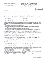
High Pressure Cutout Manifold
1. Connect the manifold
gauge to the compressor
discharge service valve
with a heavy duty, black
jacketed thick wall #HCA
144 hose with 6024 kPa,
60.24 bar, 900 psig
working pressure rating.
3. Raise the discharge pressure of the compressor by
blocking the condenser coil airflow. Temporarily
cover the compressor compartment, control box and
power cord storage compartment with cardboard to
reduce condenser coil airflow. This should increase
the discharge pressure enough to cause the switch to
open. When the switch opens:
2. Operate the unit in Cool by performing a
REFRG/FC HI (full cool with high speed evaporator
fan) test from the Test menu of the μP-D controller.
• The Alarm LED should turn On.
• The compressor and evaporator fans should
STOP immediately.
• The condenser fan should continue to operate.
NOTE: The discharge pressure should never be
allowed to exceed 2,760 kPa, 27.6 bar, 400psig.
4. Be sure to remove the cardboard installed in
step 3.
WARNING: When alarm codes are cleared by
pressing the ENTER key, the unit will start
automatically.
If the HPCO switch fails to stop compressor
operation, replace the switch and repeat steps 1
through 4.
NOTE: To clear the HPCO alarm, press the
ALARM key on the controller. Press the DOWN key
until ENTER flashes in the left display. Then press
the ENTER key. The Alarm LED should turn Off and
the unit restart.
Condenser Fan and Evaporator Fan
Rotation
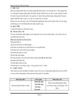
Condenser Fan
Check for proper condenser fan rotation by
placing a small cloth or sheet of paper against the
condenser fan grille on the front of the unit. Proper
rotation will blow the cloth or paper away from the
grille. Improper rotation will hold the cloth or paper
against the grille.
NOTE: If unit operating conditions do not require
condenser fan operation, check the condenser fan
rotation by performing an AMPS/CFH (high speed
condenser fan) test from the Test menu of the μP-D
controller.
If the condenser fan is rotating backwards, refer to
the unit wiring diagram to correct fan motor wiring at
the fan motor junction box or condenser fan
contactor. To correct improper fan rotation, reverse
any two fan power cord leads at the condenser fan
contactor (disconnect power supply before reversing
leads). Do not move the CH ground wire.
Evaporator Fans
Visually inspect the evaporator fan blades for
proper rotation. Arrows located on the underside of
the fan deck indicate the correct direction of rotation.
NOTE: Check both High and Low Speed evaporator
fan rotation by performing an AMPS/EFH (high
speed evaporator fan) test and AMPS/EFL (low
speed evaporator fan) test from the Test menu of the
μP-D controller.
If an evaporator fans rotate backwards on one or
both speeds, refer to the unit wiring diagram to
correct motor wiring at the fan motor junction box or
evaporator fan contactor (disconnect power supply
before reversing leads). (Do not move the ground
wire which is labeled CH.)
NOTE: Evaporator fan motor wires EF1, EF2 and
EF3 are used on LOW SPEED fan operation.
Wires EF11, EF12 and EF13 are used on HIGH
SPEED fan operation.
NOTE: To diagnose the controller phase selection
system if both the condenser fan and evaporator
fans are rotating backwards, see the Diagnosis
Manual for ThermoGuard μP-D Microprocessor
Controller. đảo dây nối đất CH.
Electric Heaters
Six electric heater elements are located
underneath the evaporator coil. If a heater element is
suspected of malfunctioning, inspect the
connections:
• If the connections appear correct and secure,
isolate and check the resistance of each individual
heater element by disconnecting it from the circuit
• Check resistance with an ohmmeter.
NOTE: When repairing heater connections, protect
the new connections from the ingress of moisture
with heat shrink tubing. All heaters should be
secured to prevent contact with sharp metal edges.
13
THANKS FOR YOUR LISTENING