Mill Series Training Manual potx
Bạn đang xem bản rút gọn của tài liệu. Xem và tải ngay bản đầy đủ của tài liệu tại đây (3.17 MB, 81 trang )
Haas Factory Outlet
A Division of Productivity Inc
Revised 022613 (032512) (printed 022613)
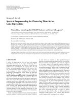
Mill Series
Training Manual
Haas CNC
Mill Operator
This Manual is the Property of Productivity Inc
The document may not be reproduced without the express written permission of
Productivity Inc.
The content must not be altered, nor may the Productivity Inc name be removed
from the materials.
This material is to be used as a guide to operation of the machine tool. The
Operator is responsible for following Safety Procedures as outlined by their
instructor or manufacturer’s specifications.
To obtain permission, please contact
Haas CNC Mill Operator Manual
Table of Contents
INTRODUCTION TO BASIC VERTICAL MILL OPERATION 5
THE CARTESIAN COORDINATE SYSTEM 7
ABSOLUTE AND INCREMENTAL POSITIONING 8
ABSOLUTE AND INCREMENTAL EXERCISE 9
VERTICAL MACHINING CENTER TRAVELS 12
THE MACHINE COORDINATE SYSTEM - MACHINE HOME POSITION 14
WORK COORDINATE SYSTEM 15
TOOL LENGTH OFFSET 18
THE HAAS CNC CONTROL 19
CONTROL DISPLAY 20
KEYBOARD INTRODUCTION 21
1 – FUNCTION KEYS 22
2 – JOG KEYS 22
3 – OVERRIDE KEYS 23
4 – DISPLAY KEYS 24
5 – CURSOR KEYS 28
6 AND 7 – ALPHA KEYS AND NUMERIC KEYS 28
8 – MODE KEYS 30
SETTINGS 33
ATC (AUTOMATIC TOOL CHANGE) 36
SETTING TOOL LENGTH & WORK ZERO OFFSETS 37
SET UP PROCEDURE 38
WORK OFFSETS (X AND Y PART ZEROS) 38
TOOL LENGTH OFFSETS 38
PROGRAM PROOFING AND RUNNING IN MEMORY 38
COMMUNICATIONS 39
HAAS MILL CONTROL TIPS 41
GENERAL TIPS 41
CONTROL TIPS 41
PRGRM /CONVRS 42
POSIT (POSITION) 42
Productivity Inc – Haas CNC Mill Operator Manual Page 2
Productivity Inc – Haas CNC Mill Operator Manual Page 3
PROGRAMMING 44
TYPICAL HAAS G-CODES: 45
TYPICAL HAAS M CODES: 46
ALPHABETICAL ADDRESS CODES 47
MACHINE DEFAULTS 51
PREPARATORY FUNCTIONS (G CODES) 52
RAPID POSITION COMMANDS (G00) 54
LINEAR & CIRCULAR INTERPOLATION COMMANDS (G01, G02) 55
MISCELLANEOUS G-CODES (G04, G03) 57
HELICAL INTERPOLATION 57
CIRCULAR POCKET MILLING (G12, G13) 58
REFERENCE POINT DEFINITION AND RETURN (G28) 60
CUTTER COMPENSATION (G40, G41, G42) G43 60
TOOL LENGTH COMPENSATION (G43) 61
ENGRAVING (G47) 62
LITERAL STRING ENGRAVING (G54-G59) 63
BOLT HOLE PATTERNS (G70, G71, G72) 64
CANNED CYCLES (G73-G89) 66
ABSOLUTE/INCREMENTAL SELECTION 75
CANNED CYCLE AUXILIARY FUNCTIONS 75
MISCELLANEOUS FUNCTIONS (M FUNCTIONS) 76
M CODE DETAILED DESCRIPTION 77
FORMULAS 79
Productivity Inc – Haas CNC Mill Operator Manual Page 4
For more information on Additional Training Opportunities
or our Classroom Schedule
Contact the Productivity Inc Applications Department in Minneapolis:
' 763.476.8600
Visit us on the Web: www.productivity.com
Click on the Training Registration Button
*
Productivity Inc – Haas CNC Mill Operator Manual Page 5
Introduction to Basic Vertical Mill Operation
Welcome to Productivity, Inc., your local Haas Factory Outlet (H.F.O.) for the Haas Mill Operator Class.
This class is intended to give a basic understanding of the set-up and operation of a Haas Machining
Center.
After 1945 design of wings for the US Air Force were becoming extremely complex and hard to
manufacture using conventional machine tools. MIT developed a machine that was able to control a
cutting tool path with a series of straight lines defined by axial coordinates at prescribed feed rates.
The first NC machine tool was introduced to the defense and aerospace industry by MIT in 1952. The
contour of a constantly changing curvature could be described by a series of short lines determined by a
series of coordinate in three axes.
The first machine tools were run with instructions or programs punched out on paper tape. The files of
the early machine tools were often in the format which later became called G-code. The reason for the
name being that many of the lines of text began the letter G.
In an NC machine, the tool is controlled by a code system that enables it to be operated with minimal
supervision and with a great deal of repeatability. "CNC" (Computerized Numerical Control) is the same
type of operating system, with the exception that a computer monitors the machine tool.
The same principles used in operating a manual machine are used in programming a NC or CNC
Machine. The main difference is that instead of cranking handles to position a slide to a certain point,
the dimension is stored in the memory of the machine control once. The control will then move the
machine to these positions each time the program is run.
The operation of the VF-Series Vertical Machining Center requires that a part program be designed,
written, and entered into the memory of the control. There are several options for getting these
programs to the control. RS-232 (serial port with a computer), 3.5” Floppy Disk, Ethernet / Networking/
and USB are all viable ways to transmit and receive programs.
In order to operate and program a CNC controlled machine, a basic understanding of machining
practices and a working knowledge of math are necessary. It is also important to become familiar with
the control console and the placement of the keys, switches, displays, etc., that are pertinent to the
operation of the machine.
This manual can be used as both an operator's manual and as a programmer's manual. It is intended to
give a basic understanding of CNC programming and its applications. It is not intended as an in-depth
study of all ranges of machine use, but as an overview of common and potential situations facing CNC
programmers. Much more training and information is necessary before attempting to program on the
machine.
The programming section of this manual is meant as a supplementary teaching aid to users of the HAAS
Vertical Machining Center. The information in this section may apply in whole or in part to the operation
of other CNC machines. Its use is intended only as an aid in the operation of the HAAS Vertical
Machining Center.
Updated CK 3/25/12
Productivity Inc – Haas CNC Mill Operator Manual Page 6
Productivity Inc – Haas CNC Mill Operator Manual Page 7
The Cartesian Coordinate System
The first diagram we are concerned with is called a NUMBER LINE. This number line has a zero reference point
location that is called an ABSOLUTE ZERO and may be placed at any point along the number line.
“X” axis
The number line also has numbered increments on either side of absolute zero.
Moving away from zero to the right are positive increments. Moving away from zero to the left are negative
increments. The “+”, or positive increments, are understood, therefore no sign is needed. We use positive and
negative signs along with increment value's to indicate its relationship to zero on the line.
Our concern is the distance and the direction from zero and is labeled as “Absolute Programming”
Remember that zero may be placed at any point along the line, and that once placed, one side of zero has negative
increments and the other side has positive increments.
Vertical Number Line know as the “Y” axis
Productivity Inc – Haas CNC Mill Operator Manual Page 8
Absolute and Incremental Positioning
There are two different systems used in positioning our machine. Both will “steer” the machine where
we need it to go, both will net the same results. The reason we use more than one, is flexibility. Below
we will talk about both, and they are the first two “G-Codes”
Absolute Positioning:
With absolute positioning, we tell the machine where to move referenced to a common point, called X0
Y0 and Z0. Every time we need to move to a certain position, the ending point of that move is in direct
relationship to this “common point”
G90 Absolute Positioning
Program to move the machine to these
4 hole locations when using G90 (Abs.)
X 1.0000 Y 1.0000
X 9.0000 Y 1.0000
X 9.0000 Y 9.0000
X 1.0000 Y 9.0000
Incremental Positioning:
With incremental positioning, we are telling the machine where to go in relationship to where it
currently is at. Basically like a set of directions given from where the machine stopped last.
G91 Incremental Positioning
Program to move the machine to the same
4 hole locations using G91 (Incr.)
X 1.0000 Y 1.0000
X 8.0000
Y 8.0000
X -8.0000
When do we decide which to use?
We switch between the two when it is more convenient. Once example is look at the above 2 prints.
Sometimes the print doesn’t call out the hole-locations, but will give the distance between the holes.
Productivity Inc – Haas CNC Mill Operator Manual Page 9
Absolute and Incremental Exercise
G90 ABSOLUTE
P1
X 0
Y
-
2.5
P2
P3
P4
P5
P6
P7
P8
P9
P10
G91 INCREMENTAL
P1
X 0
Y
-
2.5
P2
P3
P4
P5
P6
P7
P8
P9
P10
Productivity Inc – Haas CNC Mill Operator Manual Page 10
This diagram shows a front view of the grid as it would appear on the mill. This view shows the X and Y
axes as the operator faces the mill. Note that at the intersection of the two lines, a common zero point
is established.
Fig. 1-4: Operator’s working grid.
Whenever we set a zero somewhere on the X axis and somewhere on the Y axis, we have automatically
caused an intersection of the two lines. This is known as “zero”, where our X and Y lines would both be
at a value of 0. We will move this point to a “Zero” position on our part so that we can steer the
machine to locations that relate to our print. Another term for this “Zero” position is the origin of the
part.
Productivity Inc – Haas CNC Mill Operator Manual Page 11
The following illustration shows the X & Y directions of travel on a vertical machining center with respect
to a part print. It shows the positive and negative positions that our spindle would have to move with
respect to the x and y axis. Also note where these two axis meet, they create a common point of “zero”
where they both are at the value of “0” at the same point.
Vertical machining centers have 3 axis of travel. We have talked about two of them, the X (left to right
movement), the Y (moving the part towards and away from the operator), but the last to discuss is the
Z. The Z axis moves the milling spindle up or away from the part in the positive direction, and towards or
into the part in the negative direction. Now that we have discussed all 3 of the axis, we can take a look
at this picture of a Haas VF-8 VMC.
Productivity Inc – Haas CNC Mill Operator Manual Page 12
Vertical Machining Center Travels
Haas VMC (VF-8) shown with the X, Y, and Z axis
The machine illustration shows three directions of travel available on a vertical machine center. Now to
carry the number line idea a little further, imagine such a line placed along each set of travels (or axis) of
the machine.
The first number line would be the left-to-right, or “X”, axis of the machine. Positive X values would
move the spindle to the right on our part, and negative would move the spindle to the left.
If we place a similar number line along the front-to-back, or “Y” axis, and wanted to move the spindle to
the back of the table, these would be positive values. Moving the spindle towards the operator would
be negative values in the Y axis.
The third axis of travel on our machine is the up-and-down, or “Z” axis. A positive Z value will move the
spindle up towards the tool change position, and negative values would move the spindle towards our
part.
All axes of Haas VMCs have a resolution of .0001” inches (or .001mm).
Productivity Inc – Haas CNC Mill Operator Manual Page 13
Now theoretically all of our number lines for each axis are infinite in length, we are limited to the travels
of the particular machine we are using. Below is an example of the travels of different Haas VMCs
showing how much movement we have on each particular model.
VMC TRAVELS:
X-axis Y-axis Z-axis
VF-0/ VF-1 20" 16" 20"
VF-2 30" 16" 20"
VF-3 40" 20" 25"
VF-4 50" 20" 25"
VF-6 64" 32" 30"
VF-8 64" 40" 30"
VF-10 120” 32” 30”
Remember, when we are moving the machine, we are concerned with positioning the spindle. Although
the machine table is the moving part, our programs are written as if the spindle was moving.
Keep in mind that the zero position may be placed at any point along each of the three number lines,
and in fact, will probably be different for each setup of the machine.
Productivity Inc – Haas CNC Mill Operator Manual Page 14
The Machine Coordinate System - Machine Home Position
The principle of machine home may be seen when doing a reference return of all machine axes at
machine start-up. A zero return (POWER UP/RESTART) is required when you power on machine. All
three axes are moved to extreme positive locations until limit switches are reached. The reason the
machine does this is to double check its position with the “Home” switches of the machine. On power
up/restart the machine moves first up in the z axis to home and then moves to the x and y axis home
positions at the same time.
At home position the X, Y and Z axis are all at machine 0.
This is crucial to the operation and function of a CNC machine as all of our programs, fixtures, and
tooling are based off of the machine home position described as X0, Y0, Z0.
Productivity Inc – Haas CNC Mill Operator Manual Page 15
Work Coordinate System
What is a “Work Coordinate”?
A work coordinate (also known as a part offset) is how we tell the machine where our part(s) are located
with respect to the machine home position. Under the Work Offsets page in the control, we put the
machine in jog and hand wheel the machine to the X & Y “Zero” location for our part, and use the “Part
Offset Measure” key under the Reset key to set the corresponding work offset from our program (G54,
G55, G56, etc… )
Above: The relationship of machine home to “work home”, otherwise known as “work offset”
Note: Because the location of machine home zero is in the upper right hand corner of the machine table
our values for X and Y will always be negative.
G54 – G59 Work Offsets
These are the first G-Codes that were assigned to work coordinates. This how we tell the machine that
we are working on part #1, part #2, etc. thru part #6. Originally no one thought we would need more
than 6 part offsets, but thru time and the invention of new types of machines more needed.
G154 P1 – G154 P99 Work Offsets
These codes are the same as G54 to G59, they add more places as X & Y zero. We now can set up to 105
different “zeros” within the travels of our machine. On older Haas machines the extra work offsets were
G110 to G129.
Productivity Inc – Haas CNC Mill Operator Manual Page 16
Other Work Coordinate Offsets
G52 Work Coordinate Shift
G52 will “shift” all work offsets that are set in the machine. In the Work Offsets page of the control, if we
input a value of X +1.0000, ALL of the offsets will move one to the right by a value of 1.0000. This is most
commonly used in casting and forging work where we have core movement.
Note: The G52 command works differently depending on the value of Setting 33. This setting
selects the FANUC, HAAS, or YASNAC style of coordinates, which are listed below.
G53 Positioning In Reference to Machine Home
G53 is used when we want to move the machine a certain distance and location from Machine Home.
This is quite often used if we want to establish a safe tool change position because we have large parts
or tools and need to clear the tool changer. G53 is non-modal and only applies to the block which it is in.
G92 Set Work Coordinate System
G92 Can be used to set our work offsets while “on the fly” in our program. G92 was used back when
machines only had one offset to choose from. We had to cut our first part, move the spindle over to the
second part X&Y zero, and then call G92 X0Y0 in our program. Our work offset is now set around the
second part. Using G54 – G154 P99 is much faster, more tunable, and easier to use.
Productivity Inc – Haas CNC Mill Operator Manual Page 17
Multiple Work Coordinate System
Multiple fixture setup
The figure above represents a multiple-fixture setup. Each vise will have an absolute zero once it is
specified in the program. This is done by using G54 through G59. G54 through G59 and
G154 P1 through G154 P99 gives a total of 105 different work offsets which may be used.
Productivity Inc – Haas CNC Mill Operator Manual Page 18
Tool Length Offset
The tool length offset is how we tell the machine where the top face of our part is located in
the Z direction with respect to machine home. The tool length offset gives the distance from
the end of the tool at home position to the top face of our part or other plane that the
programmer has determined as the Z zero reference point. This information is stored in the
Tool Offset Memory.
Each tool in the machine will have its own defined tool length stored in the tool offset register
determined by the operator during set up. Other information about each tool is stored in the
Tool Offset Register. For each tool, the coolant tube position and the diameter or radius are
also stored. In the wear section, small alterations to the tool length and diameter or radius are
stored. If you cursor to the right in the tool register, additional information about the tool may
be stored: the number of flutes, the actual diameter, the tool type, and tool category with
respect to size and weight.
In the illustration below the spindle is sitting at the Z home position and shows the distance the spindle
must go to reach +.100 above the face of the part. G43 code with an H-number tells the machine which
tool length offset to use.
Productivity Inc – Haas CNC Mill Operator Manual Page 19
The Haas CNC Control
Powering On the Machine
To power up a Haas machine, regardless of where the machine table was when it was turned off, press
POWER ON. The machine must first find its fixed machine zero reference point before any operations
can occur. After it's powered on, pressing POWER UP/RESTART will send the machine to its machine
zero reference location. The machine doors must be cycled and closed to return to machine zero. Also
the machine needs to see the Emergency Stop cycled. Haas provides directions on the screen on what
needs to be done to start the machine up in the morning.
When powering on the machine, if there is a message in the MESGS
display, it will be the first display seen on your control screen.
Will move all axis to machine zero and then changes tools to put
tool #1 in the spindle. Machine will move up in Z first then the X
and Y move to machine zero.
If the correct program has been selected and the part program is
proven to be good and it's ready to run, press cycle start.
General Machine Keys
Power On - Turns CNC machine on.
Power Off - Turns CNC machine tool off.
Emergency Stop - Stops all axis motion, stops spindle, tool changer and turns off coolant pump.
Jog Handle – Jogs axis selected, also may be used to scroll through programs, menu items while editing
and also altering feeds and speeds.
Cycle Start – Starts program in run mode or graphics mode.
Feed Hold – Stops all axis motion. Spindle will continue to turn.
Reset – Stops machine, will rewind program.
Power Up/Restart – Axis will return to machine zero and tool change will occur per Setting 81
Recover – If a tool change is stopped in middle of a cycle an alarm will come up. Push the Recover
button and follow the instructions to bring the tool change cycle to the beginning.
Productivity Inc – Haas CNC Mill Operator Manual Page 20
Control Display
The new 16 software has a larger display and more panes than older versions. Above is the basic display
layout. What is displayed depends on which display keys have been used. The only pane active is the
one with the white background. Only when a pane is active may changes be made to data.
Control functions in Haas machine tools are organized in three modes: Setup, Edit and Operation
Access Modes using the mode keys as follows:
Setup: ZERO RET, HAND JOG keys. Provides all control features for machine setup.
Edit: EDIT, MDI/DNC, LIST PROG keys. Provides all program editing, management, and transfer
functions.
Operation: MEM key. Provides all control features necessary to make a part.
Current mode is displayed at top of display.
Functions from another mode can still be accessed within the active mode. For example, while in the
Operation mode, pressing OFFSET will display the offset tables as the active pane in the Main Display
Pane and offsets may be altered; press OFFSET to toggle the offset display. While running a part in
operation mode another program may be edited in the Main Display Pane. Press PROGRM CONVRS in
most modes to shift to the edit pane for the current active program.
Productivity Inc – Haas CNC Mill Operator Manual Page 21
Keyboard Introduction
The keyboard is divided into eight different sectors: Function Keys, Jog Keys, Override Keys,
Display Keys, Cursor Keys, Alpha Keys, Number Keys and Mode Keys. In addition, there are
miscellaneous keys and features located on the pendant and keyboard which are described briefly
on the following pages.
1-Function Keys
2-Jog Keys
3-Override
5-Cursor Keys
4-Display Keys
6-Alpha Keys 7-Number Keys
8-Mode Keys
Productivity Inc – Haas CNC Mill Operator Manual Page 22
1 – Function Keys
F1 – F4 – Perform different functions depending on which mode the machine is in. Example in offsets
mode F1 will directly enter value that you give it into to offset register.
TOOL OFFSET MEASURE – Will take machine Z position readout at bottom of offset screen and load
it in to the highlighted tool offset register.
NEXT TOOL – After pressing Tool Offset Measure button in a set up this will select the next tool and
make a tool change
TOOL RELEASE - Releases tool from spindle in MDI, Zero Return or Handle mode. A button on the
front of the spindle will do the same thing.
PART ZERO SET – Records work coordinate offsets into the highlighted register.
2 – Jog Keys
Chip FWD (Chip Auger Forward) – Turns the optional chip auger in a direction that removes chips from
the work cell.
Chip Stop (Chip Auger Stop) – Stops auger movement.
Chip REV (Chip Auger Reverse) – Turns the chip auger in reverse.
CLNT UP (Coolant Up) – Pressing this key will position the coolant stream one position higher.
CLNT DOWN (Coolant Down) – Pressing this key positions the coolant stream one position lower.
Coolant stream position will appear in tool length offset register when position is highlighted.
AUX CLNT (Auxiliary Coolant) – Turns on the optional Through-the-Spindle (TSC) coolant (in MDI
mode).
+X, -X (Axis) Selects the X axis for continuous motion when depressed.
+Y, -Y (Axis) Selects the Y axis for continuous motion when depressed.
+Z, -Z (Axis) Selects the Z axis for continuous motion when depressed.
+A, -A (Axis) Selects the A axis. This key selects the B axis when used with the SHIFT key if the machine
is configured with a fifth-axis option.
Jog Lock – When this is pressed prior to one of the jog keys given above, the axis moves in a
continuous motion without the need to hold down the axis key. Depressing this key again stops jogging
motion. Feed rate is determined by the selection in HAND JOG mode keys.
Productivity Inc – Haas CNC Mill Operator Manual Page 23
3 – Override Keys
The overrides are at the lower right of the control panel. They give the user the ability to override the
speed of rapid traverse motion, as well as programmed feeds and spindle speeds.
-10 FEED RATE Decreases current feed rate in increments of 10 percent.
100% FEED RATE Resets the control feed rate to the programmed feed rate.
+10 FEED RATE Increases current feed rate in increments of 10 percent.
HANDLE CONTROL FEED RATE Hand wheel will control feed rate at 1% increments.
-10 SPINDLE Decreases current spindle speed in increments of 10 percent.
100% SPINDLE Sets the control spindle speed at the programmed spindle speed
+10 SPINDLE Increases current spindle speed in increments of 10 percent.
HANDLE CONTROL FEED Hand wheel will control feed rate at 1% increments.
CW Starts the spindle in the clockwise direction.
STOP Stops the spindle.
CCW Starts the spindle in the counterclockwise direction.
5% RAPID Limits rapid to 5 percent of maximum.
25% RAPID Limits rapid to 25 percent of maximum.
50% RAPID Limits rapid to 50 percent of maximum.
100% RAPID Allows rapid traverse to feed at its maximum.
Override Usage
Feed rates may be varied from 0% to 999%. Feed rate override is ineffective during G74 and G84
tapping cycles. Spindle speeds may be varied from 0% to 999%. Depressing Handle Control Feed rate or
Handle Control Spindle keys, the jog handle movement varies by +/-1% increments.
Setting 10 will limit rapid movement to 50%.
Settings 19, 20, 21 make it possible to disable override keys.
Coolant may be over rode by depressing COOLNT button.
Feed Hold - Stops rapid and feed moves. Cycle Start button must be depressed to resume machine
feeds. Similar situation applies when Door Hold appears. Door must be closed and Cycle Start pressed
to continue running program.
Overrides may be reset to defaults with a M06, M30 or pressing RESET by changing Settings 83, 87 and
88 respectively.