PLANT ENGINEERING MAINTENANCE SERIES doc
Bạn đang xem bản rút gọn của tài liệu. Xem và tải ngay bản đầy đủ của tài liệu tại đây (11.15 MB, 302 trang )
20 | MOBLEY.FM Page i Wednesday, March 3, 1999 2:29 PM
ROOT CAUSE FAILURE
ANALYSIS
20 | MOBLEY.FM Page ii Wednesday, March 3, 1999 2:29 PM
P
LANT
E
NGINEERING
M
AINTENANCE
S
ERIES
Vibration Fundamentals
R. Keith Mobley
Root Cause Failure Analysis
R. Keith Mobley
Maintenance Fundamentals
R. Keith Mobley
20 | MOBLEY.FM Page iii Wednesday, March 3, 1999 2:29 PM
ROOT CAUSE FAILURE
ANALYSIS
R. Keith Mobley
Boston Oxford Auckland Johannesburg Melbourne New Delhi
20 | MOBLEY.FM Page iv Wednesday, March 3, 1999 2:29 PM
Newnes is an imprint of Butterworth–Heinemann.
Copyright © 1999 by Butterworth–Heinemann
A member of the Reed Elsevier group
All rights reserved.
No part of this publication may be reproduced, stored in a retrieval system, or transmitted in
any form or by any means, electronic, mechanical, photocopying, recording, or otherwise, with-
out the prior written permission of the publisher.
Recognizing the importance of preserving what has been written, Butterworth–Heinemann
prints its books on acid-free paper whenever possible.
Library of Congress Cataloging-in-Publication Data
Mobley, R. Keith, 1943-
Root cause failure analysis / by R. Keith Mobley.
p. cm. — (Plant engineering maintenance series)
Includes index.
ISBN 0-7506-7158-0 (alk. paper)
1. Plant maintenance. 2. System failures (Engineering)
I. Title. II. Series.
TS192.M625 1999
658.2’02—dc21 98-32097
CIP
British Library Cataloguing-in-Publication Data
A catalogue record for this book is available from the British Library.
The publisher offers special discounts on bulk orders of this book.
For information, please contact:
Manager of Special Sales
Butterworth–Heinemann
225 Wildwood Avenue
Woburn, MA 01801–2041
Tel: 781-904-2500
Fax: 781-904-2620
For information on all Newnes publications available, contact our World Wide Web home page
at:
10 9 8 7 6 5 4 3 2 1
Printed in the United States of America
Part I THEORY: INTRODUCTION
TO VIBRATION ANALYSIS 1
Chapter 1 INTRODUCTION 2
Chapter 2 VIBRATION
Chapter 3 VIBRATION
Chapter 4 VIBRATION
Chapter 5 VIBRATION
Chapter 6 MACHINE
Chapter 7 VIBRATION DATA
Chapter 9 ANALYSIS
ANALYSIS APPLICATIONS 3
ANALYSIS OVERVIEW 6
SOURCES 13
THEORY 17
DYNAMICS 26
TYPES AND FORMATS 42
Chapter 8 DATA ACQUISITION 49
TECHNIQUES 60
Part II FREQUENCY-DOMAIN
VIBRATION ANALYSIS 65
Chapter 10 OVERVIEW 66
Chapter 11 MACHINE-TRAIN
Chapter 12 DATABASE
Chapter 13 VIBRATION DATA
Chapter 14 TRENDING
Chapter 15 FAILURE-MODE
MONITORING PARAMETERS 71
DEVELOPMENT 97
ACQUISITION 112
ANALYSIS 125
ANALYSIS 138
Chapter 16 SIGNATURE
ANALYSIS 181
Chapter 17 ROOT-CAUSE
ANALYSIS 189
Part III RESONANCE AND
CRITICAL SPEED ANALYSIS 200
Chapter 18 INTRODUCTION 201
Chapter 19 TYPES OF
Chapter 20 EXAMPLES OF
Chapter 21 TESTING FOR
RESONANCE 202
RESONANCE 208
RESONANCE 213
Chapter 22 MODE SHAPE 222
Part IV REAL-TIME ANALYSIS 224
Chapter 23 OVERVIEW 225
Chapter 25 DATA
Chapter 27 TRANSIENT
Chapter 28 SYNCHRONOUS
Chapter 30 TORSIONAL
Chapter 24 APPLICATIONS 230
ACQUISITION 235
Chapter 26 ANALYSIS SETUP 246
(WATERFALL) ANALYSIS 255
TIME AVERAGING 259
Chapter 29 ZOOM ANALYSIS 265
ANALYSIS 267
GLOSSARY 286
LIST OF ABBREVIATIONS 291
INDEX 293
01.Mobley.1-6 Page 1 Friday, February 5, 1999 9:44 AM
Part I
THEORY: INTRODUCTION TO
VIBRATION ANALYSIS
Part I is an introduction to vibration analysis that covers basic vibration theory. All
mechanical equipment in motion generates a vibration profile, or signature, that
reflects its operating condition. This is true regardless of speed or whether the mode
of operation is rotation, reciprocation, or linear motion. Vibration analysis is applica-
ble to all mechanical equipment, although a common—yet invalid—assumption is
that it is limited to simple rotating machinery with running speeds above 600 revolu-
tions per minute (rpm). Vibration profile analysis is a useful tool for predictive main-
tenance, diagnostics, and many other uses.
1
01.Mobley.1-6 Page 2 Friday, February 5, 1999 9:44 AM
Chapter 1
INTRODUCTION
Several predictive maintenance techniques are used to monitor and analyze critical
machines, equipment, and systems in a typical plant. These include vibration analysis,
ultrasonics, thermography, tribology, process monitoring, visual inspection, and other
nondestructive analysis techniques. Of these techniques, vibration analysis is the
dominant predictive maintenance technique used with maintenance management pro-
grams.
Predictive maintenance has become synonymous with monitoring vibration character-
istics of rotating machinery to detect budding problems and to head off catastrophic
failure. However, vibration analysis does not provide the data required to analyze
electrical equipment, areas of heat loss, the condition of lubricating oil, or other
parameters typically evaluated in a maintenance management program. Therefore, a
total plant predictive maintenance program must include several techniques, each
designed to provide specific information on plant equipment.
2
01.Mobley.1-6 Page 3 Friday, February 5, 1999 9:44 AM
Chapter 2
VIBRATION ANALYSIS APPLICATIONS
The use of vibration analysis is not restricted to predictive maintenance. This tech-
nique is useful for diagnostic applications as well. Vibration monitoring and analysis
are the primary diagnostic tools for most mechanical systems that are used to manu-
facture products. When used properly, vibration data provide the means to maintain
optimum operating conditions and efficiency of critical plant systems. Vibration anal-
ysis can be used to evaluate fluid flow through pipes or vessels, to detect leaks, and to
perform a variety of nondestructive testing functions that improve the reliability and
performance of critical plant systems.
Some of the applications that are discussed briefly in this chapter are predictive main-
tenance, acceptance testing, quality control, loose part detection, noise control, leak
detection, aircraft engine analyzers, and machine design and engineering. Table 2.1
lists rotating, or centrifugal, and nonrotating equipment, machine-trains, and continu-
ous processes typically monitored by vibration analysis.
Table 2.1 Equipment and Processes Typically Monitored by Vibration Analysis
Centrifugal Reciprocating Continuous Process
Pumps
Compressors
Blowers
Fans
Motor/generators
Ball mills
Chillers
Pumps
Compressors
Diesel engines
Gasoline engines
Cylinders
Other machines
Continuous casters
Hot and cold strip lines
Annealing lines
Plating lines
Paper machines
Can manufacturing lines
Pickle lines
continued
3
01.Mobley.1-6 Page 4 Friday, February 5, 1999 9:44 AM
4 Vibration Fundamentals
Table 2.1 Equipment and Processes Typically Monitored by Vibration Analysis
Centrifugal Machine-Trains Continuous Process
Product rolls Boring machines Printing
Mixers Hobbing machines Dyeing and finishing
Gearboxes Machining centers Roofing manufacturing lines
Centrifuges Temper mills Chemical production lines
Transmissions Metal-working machines Petroleum production lines
Turbines Rolling mills, and most Neoprene production lines
Generators machining equipment Polyester production lines
Rotary dryers Nylon production lines
Electric motors Flooring production lines
All rotating machinery Continuous process lines
Source: Integrated Systems, Inc.
P
REDICTIVE
M
AINTENANCE
The fact that vibration profiles can be obtained for all machinery that has rotating or
moving elements allows vibration-based analysis techniques to be used for predic-
tive maintenance. Vibration analysis is one of several predictive maintenance tech-
niques used to monitor and analyze critical machines, equipment, and systems in a
typical plant. However, as indicated before, the use of vibration analysis to monitor
rotating machinery to detect budding problems and to head off catastrophic failure is
the dominant predictive maintenance technique used with maintenance management
programs.
A
CCEPTANCE
T
ESTING
Vibration analysis is a proven means of verifying the actual performance versus
design parameters of new mechanical, process, and manufacturing equipment. Preac-
ceptance tests performed at the factory and immediately following installation can be
used to ensure that new equipment performs at optimum efficiency and expected life-
cycle cost. Design problems as well as possible damage during shipment or installa-
tion can be corrected before long-term damage and/or unexpected costs occur.
Q
UALITY
C
ONTROL
Production-line vibration checks are an effective method of ensuring product qual-
ity where machine tools are involved. Such checks can provide advanced warning
that the surface finish on parts is nearing the rejection level. On continuous pro-
cess lines such as paper machines, steel-finishing lines, or rolling mills, vibration
01.Mobley.1-6 Page 5 Friday, February 5, 1999 9:44 AM
5 Vibration Analysis Applications
analysis can prevent abnormal oscillation of components that result in loss of
product quality.
L
OOSE OR
F
OREIGN
P
ARTS
D
ETECTION
Vibration analysis is useful as a diagnostic tool for locating loose or foreign objects in
process lines or vessels. This technique has been used with great success by the
nuclear power industry and it offers the same benefits to non-nuclear industries.
N
OISE
C
ONTROL
Federal, state, and local regulations require serious attention be paid to noise levels
within the plant. Vibration analysis can be used to isolate the source of noise gener-
ated by plant equipment as well as background noises such as those generated by
fluorescent lights and other less obvious sources. The ability to isolate the source of
abnormal noises permits cost-effective corrective action.
L
EAK
D
ETECTION
Leaks in process vessels and devices such as valves are a serious problem in many
industries. A variation of vibration monitoring and analysis can be used to detect leak-
age and isolate its source. Leak-detection systems use an accelerometer attached to
the exterior of a process pipe. This allows the vibration profile to be monitored in
order to detect the unique frequencies generated by flow or leakage.
AIRCRAFT ENGINE ANALYZERS
Adaptations of vibration analysis techniques have been used for a variety of specialty
instruments, in particular, portable and continuous aircraft engine analyzers. Vibration
monitoring and analysis techniques are the basis of these analyzers, which are used
for detecting excessive vibration in turboprop and jet engines. These instruments
incorporate logic modules that use existing vibration data to evaluate the condition of
the engine. Portable units have diagnostic capabilities that allow a mechanic to deter-
mine the source of the problem while continuous sensors alert the pilot to any devia-
tion from optimum operating condition.
M
ACHINE
D
ESIGN AND
E
NGINEERING
Vibration data have become a critical part of the design and engineering of new
machines and process systems. Data derived from similar or existing machinery can
be extrapolated to form the basis of a preliminary design. Prototype testing of new
machinery and systems allows these preliminary designs to be finalized, and the
vibration data from the testing adds to the design database.
01.Mobley.1-6 Page 6 Friday, February 5, 1999 9:44 AM
Chapter 3
VIBRATION ANALYSIS OVERVIEW
Vibration theory and vibration profile, or signature, analyses are complex subjects that
are the topic of many textbooks. The purpose of this chapter is to provide enough the-
ory to allow the concept of vibration profiles and their analyses to be understood
before beginning the more in-depth discussions in the later sections of this module.
T
HEORETICAL
V
IBRATION
P
ROFILES
A vibration is a periodic motion or one that repeats itself after a certain interval of
time. This time interval is referred to as the period of the vibration, T. A plot, or pro-
file, of a vibration is shown in Figure 3.1, which shows the period, T, and the maxi-
1
mum displacement or amplitude, X
0
. The inverse of the period,
, is called the
T
frequency, f, of the vibration, which can be expressed in units of cycles per second
(cps) or Hertz (Hz). A harmonic function is the simplest type of periodic motion and
is shown in Figure 3.2, which is the harmonic function for the small oscillations of a
simple pendulum. Such a relationship can be expressed by the equation:
X = X
0
sin(ωt) ,
where
X = Vibration displacement (thousandths of an inch, or mils)
X
0
= Maximum displacement or amplitude (mils)
ω = Circular frequency (radians per second)
t = Time (seconds).
6
01.Mobley.1-6 Page 7 Friday, February 5, 1999 9:44 AM
7 Vibration Analysis Overview
Figure 3.1 Periodic motion for bearing pedestal of a steam turbine.
Figure 3.2 Small oscillations of a simple pendulum, harmonic function.
01.Mobley.1-6 Page 8 Friday, February 5, 1999 9:44 AM
8 Vibration Fundamentals
A
CTUAL
V
IBRATION
P
ROFILES
The process of vibration analysis requires the gathering of complex machine data,
which must then be deciphered. As opposed to the simple theoretical vibration curves
shown in Figures 3.1 and 3.2 above, the profile for a piece of equipment is extremely
complex. This is true because there are usually many sources of vibration. Each
source generates its own curve, but these are essentially added and displayed as a
composite profile. These profiles can be displayed in two formats: time domain and
frequency domain.
Time Domain
Vibration data plotted as amplitude versus time is referred to as a time-domain data
profile. Some simple examples are shown in Figures 3.1 and 3.2. An example of the
complexity of these type of data for an actual piece of industrial machinery is shown
in Figure 3.3.
Time-domain plots must be used for all linear and reciprocating motion machinery.
They are useful in the overall analysis of machine-trains to study changes in operating
conditions. However, time-domain data are difficult to use. Because all of the vibra-
tion data in this type of plot are added to represent the total displacement at any given
time, it is difficult to determine the contribution of any particular vibration source.
The French physicist and mathematician Jean Fourier determined that nonharmonic
data functions such as the time-domain vibration profile are the mathematical sum of
Figure 3.3 Example of a typical time-domain vibration profile for a piece of machinery.
01.Mobley.1-6 Page 9 Friday, February 5, 1999 9:44 AM
9 Vibration Analysis Overview
Figure 3.4 Discrete (harmonic) and total (nonharmonic) time-domain vibration curves.
simple harmonic functions. The dashed-line curves in Figure 3.4 represent discrete
harmonic components of the total, or summed, nonharmonic curve represented by the
solid line.
These type of data, which are routinely taken during the life of a machine, are directly
comparable to historical data taken at exactly the same running speed and load. How-
ever, this is not practical because of variations in day-to-day plant operations and
changes in running speed. This significantly affects the profile and makes it impossi-
ble to compare historical data.
Frequency Domain
From a practical standpoint, simple harmonic vibration functions are related to the
circular frequencies of the rotating or moving components. Therefore, these frequen-
cies are some multiple of the basic running speed of the machine-train, which is
expressed in revolutions per minute (rpm) or cycles per minute (cpm). Determining
01.Mobley.1-6 Page 10 Friday, February 5, 1999 9:44 AM
10 Vibration Fundamentals
Figure 3.5 Typical frequency-domain vibration signature.
these frequencies is the first basic step in analyzing the operating condition of the
machine-train.
Frequency-domain data are obtained by converting time-domain data using a mathe-
matical technique referred to as a fast Fourier transform (FFT). FFT allows each
vibration component of a complex machine-train spectrum to be shown as a discrete
frequency peak. The frequency-domain amplitude can be the displacement per unit
time related to a particular frequency, which is plotted as the Y-axis against frequency
as the X-axis. This is opposed to the time-domain spectrum, which sums the velocities
of all frequencies and plots the sum as the Y-axis against time as the X-axis. An exam-
ple of a frequency-domain plot or vibration signature is shown in Figure 3.5.
Frequency-domain data are required for equipment operating at more than one run-
ning speed and all rotating applications. Because the X-axis of the spectrum is fre-
quency normalized to the running speed, a change in running speed will not affect the
plot. A vibration component that is present at one running speed will still be found in
the same location on the plot for another running speed after the normalization,
although the amplitude may be different.
01.Mobley.1-6 Page 11 Friday, February 5, 1999 9:44 AM
11 Vibration Analysis Overview
Interpretation of Vibration Data
The key to using vibration signature analysis for predictive maintenance, diagnostic,
and other applications is the ability to differentiate between normal and abnormal
vibration profiles. Many vibrations are normal for a piece of rotating or moving
machinery. Examples of these are normal rotations of shafts and other rotors, contact
with bearings, gear-mesh, etc. However, specific problems with machinery generate
abnormal, yet identifiable, vibrations. Examples of these are loose bolts, misaligned
shafts, worn bearings, leaks, and incipient metal fatigue.
Predictive maintenance utilizing vibration signature analysis is based on the following
facts, which form the basis for the methods used to identify and quantify the root
causes of failure:
1. All common machinery problems and failure modes have distinct vibra-
tion frequency components that can be isolated and identified.
2. A frequency-domain vibration signature is generally used for the analysis
because it is comprised of discrete peaks, each representing a specific
vibration source.
3. There is a cause, referred to as a forcing function, for every frequency
component in a machine-train’s vibration signature.
4. When the signature of a machine is compared over time, it will repeat until
some event changes the vibration pattern (i.e., the amplitude of each dis-
tinct vibration component will remain constant until there is a change in
the operating dynamics of the machine-train).
While an increase or a decrease in amplitude may indicate degradation of the
machine-train, this is not always the case. Variations in load, operating practices, and
a variety of other normal changes also generate a change in the amplitude of one or
more frequency components within the vibration signature. In addition, it is important
to note that a lower amplitude does not necessarily indicate an improvement in the
mechanical condition of the machine-train. Therefore, it is important that the source
of all amplitude variations be clearly understood.
V
IBRATION
M
EASURING
E
QUIPMENT
Vibration data are obtained by the following procedure: (1) Mount a transducer onto
the machinery at various locations, typically machine housing and bearing caps, and
(2) use a portable data-gathering device, referred to as a vibration monitor or analyzer,
to connect to the transducer to obtain vibration readings.
Transducer
The transducer most commonly used to obtain vibration measurements is an acceler-
ometer. It incorporates piezoelectric (i.e., pressure-sensitive) films to convert mechan-
ical energy into electrical signals. The device generally incorporates a weight
01.Mobley.1-6 Page 12 Friday, February 5, 1999 9:44 AM
12 Vibration Fundamentals
suspended between two piezoelectric films. The weight moves in response to vibra-
tion and squeezes the piezoelectric films, which sends an electrical signal each time
the weight squeezes it.
Portable Vibration Analyzer
The portable vibration analyzer incorporates a microprocessor that allows it to con-
vert the electrical signal mathematically to acceleration per unit time, perform a FFT,
and store the data. It can be programmed to generate alarms and displays of the data.
The data stored by the analyzer can be downloaded to a personal or a more powerful
computer to perform more sophisticated analyses, data storage and retrieval, and
report generation.
01.Mobley.1-6 Page 13 Friday, February 5, 1999 9:44 AM
Chapter 4
VIBRATION SOURCES
All machinery with moving parts generates mechanical forces during normal opera-
tion. As the mechanical condition of the machine changes due to wear, changes in the
operating environment, load variations, etc., so do these forces. Understanding
machinery dynamics and how forces create unique vibration frequency components is
the key to understanding vibration sources.
Vibration does not just happen. There is a physical cause, referred to as a forcing
function, and each component of a vibration signature has its own forcing function.
The components that make up a signature are reflected as discrete peaks in the FFT or
frequency-domain plot.
The vibration profile that results from motion is the result of a force imbalance. By
definition, balance occurs in moving systems when all forces generated by, and acting
on, the machine are in a state of equilibrium. In real-world applications, however,
there is always some level of imbalance and all machines vibrate to some extent. This
chapter discusses the more common sources of vibration for rotating machinery, as
well as for machinery undergoing reciprocating and/or linear motion.
R
OTATING
M
ACHINERY
A rotating machine has one or more machine elements that turn with a shaft, such as
rolling-element bearings, impellers, and other rotors. In a perfectly balanced machine,
all rotors turn true on their centerline and all forces are equal. However, in industrial
machinery, it is common for an imbalance of these forces to occur. In addition to
imbalance generated by a rotating element, vibration may be caused by instability in
the media flowing through the rotating machine.
13
01.Mobley.1-6 Page 14 Friday, February 5, 1999 9:44 AM
14 Vibration Fundamentals
Rotor Imbalance
While mechanical imbalance generates a unique vibration profile, it is not the only
form of imbalance that affects rotating elements. Mechanical imbalance is the condi-
tion where more weight is on one side of a centerline of a rotor than on the other. In
many cases, rotor imbalance is the result of an imbalance between centripetal forces
generated by the rotation. The source of rotor vibration also can be an imbalance
between the lift generated by the rotor and gravity.
Machines with rotating elements are designed to generate vertical lift of the rotating
element when operating within normal parameters. This vertical lift must overcome
gravity to properly center the rotating element in its bearing-support structure. How-
ever, because gravity and atmospheric pressure vary with altitude and barometric
pressure, actual lift may not compensate for the downward forces of gravity in certain
environments. When the deviation of actual lift from designed lift is significant, a
rotor might not rotate on its true centerline. This offset rotation creates an imbalance
and a measurable level of vibration.
Flow Instability and Operating Conditions
Rotating machines subject to imbalance caused by turbulent or unbalanced media
flow include pumps, fans, and compressors. A good machine design for these units
incorporates the dynamic forces of the gas or liquid in stabilizing the rotating ele-
ment. The combination of these forces and the stiffness of the rotor-support system
(i.e., bearing and bearing pedestals) determine the vibration level. Rotor-support stiff-
ness is important because unbalanced forces resulting from flow instability can deflect
rotating elements from their true centerline, and the stiffness resists the deflection.
Deviations from a machine’s designed operating envelope can affect flow stability,
which directly affects the vibration profile. For example, the vibration level of a cen-
trifugal compressor is typically low when operating at 100% load with laminar air-
flow through the compressor. However, a radical change in vibration level can result
from decreased load. Vibration resulting from operation at 50% load may increase by
as much as 400% with no change in the mechanical condition of the compressor. In
addition, a radical change in vibration level can result from turbulent flow caused by
restrictions in either the inlet or discharge piping.
Turbulent or unbalanced media flow (i.e., aerodynamic or hydraulic instability) does
not have the same quadratic impacts on the vibration profile as that of load change,
but it increases the overall vibration energy. This generates a unique profile that can
be used to quantify the level of instability present in the machine. The profile gener-
ated by unbalanced flow is visible at the vane or blade-pass frequency of the rotating
element. In addition, the profile shows a marked increase in the random noise gener-
ated by the flow of gas or liquid through the machine.
01.Mobley.1-6 Page 15 Friday, February 5, 1999 9:44 AM
15 Vibration Sources
Mechanical Motion and Forces
A clear understanding of the mechanical movement of machines and their compo-
nents is an essential part of vibration analysis. This understanding, coupled with the
forces applied by the process, are the foundation for diagnostic accuracy.
Almost every unique frequency contained in the vibration signature of a machine-
train can be directly attributed to a corresponding mechanical motion within the
machine. For example, the constant end play or axial movement of the rotating ele-
ment in a motor-generator set generates an elevated amplitude at the fundamental
(1×
), second harmonic (2×), and third harmonic (3×) of the shaft’s true running
speed. In addition, this movement increases the axial amplitude of the fundamental
(1×
) frequency.
Forces resulting from air or liquid movement through a machine also generate unique
frequency components within the machine’s signature. In relatively stable or laminar-
flow applications, the movement of product through the machine slightly increases
the amplitude at the vane or blade-pass frequency. In more severe, turbulent-flow
applications, the flow of product generates a broadband, white noise profile that can
be directly attributed to the movement of product through the machine.
Other forces, such as the side-load created by V-belt drives, also generate unique fre-
quencies or modify existing component frequencies. For example, excessive belt ten-
sion increases the side-load on the machine-train’s shafts. This increase in side-load
changes the load zone in the machine’s bearings. The result of this change is a marked
increase in the amplitude at the outer-race rotational frequency of the bearings.
Applied force or induced loads can also displace the shafts in a machine-train. As a
result the machine’s shaft will rotate off-center which dramatically increases the
amplitude at the fundamental (1
×) frequency of the machine.
R
ECIPROCATING AND
/
OR
L
INEAR
-M
OTION
M
ACHINERY
This section describes machinery that exhibits reciprocating and/or linear motion(s)
and discusses typical vibration behavior for these types of machines.
Machine Descriptions
Reciprocating linear-motion machines incorporate components that move linearly in a
reciprocating fashion to perform work. Such reciprocating machines are bidirectional
in that the linear movement reverses, returning to the initial position with each com-
pleted cycle of operation. Nonreciprocating linear-motion machines incorporate com-
ponents that also generate work in a straight line, but do not reverse direction within
one complete cycle of operation.
01.Mobley.1-6 Page 16 Friday, February 5, 1999 9:44 AM
16 Vibration Fundamentals
Few machines involve linear reciprocating motion exclusively. Most incorporate a
combination of rotating and reciprocating linear motions to produce work. One exam-
ple of such a machine is a reciprocating compressor. This unit contains a rotating
crankshaft that transmits power to one or more reciprocating pistons, which move lin-
early in performing the work required to compress the media.
Sources of Vibration
Like rotating machinery, the vibration profile generated by reciprocating and/or lin-
ear-motion machines is the result of mechanical movement and forces generated by
the components that are part of the machine. Vibration profiles generated by most
reciprocating and/or linear-motion machines reflect a combination of rotating and/or
linear-motion forces.
However, the intervals or frequencies generated by these machines are not always
associated with one complete revolution of a shaft. In a two-cycle reciprocating
engine, the pistons complete one cycle each time the crankshaft completes one 360-
degree revolution. In a four-cycle engine, the crank must complete two complete rev-
olutions, or 720 degrees, in order to complete a cycle of all pistons.
Because of the unique motion of reciprocating and linear-motion machines, the level
of unbalanced forces generated by these machines is substantially higher than those
generated by rotating machines. As an example, a reciprocating compressor drives
each of its pistons from bottom-center to top-center and returns to bottom-center in
each complete operation of the cylinder. The mechanical forces generated by the
reversal of direction at both top-center and bottom-center result in a sharp increase in
the vibration energy of the machine. An instantaneous spike in the vibration profile
repeats each time the piston reverses direction.
Linear-motion machines generate vibration profiles similar to those of reciprocating
machines. The major difference is the impact that occurs at the change of direction
with reciprocating machines. Typically, linear-motion-only machines do not reverse
direction during each cycle of operation and, as a result, do not generate the spike of
energy associated with direction reversal.
01.Mobley.1-6 Page 17 Friday, February 5, 1999 9:44 AM
Chapter 5
VIBRATION THEORY
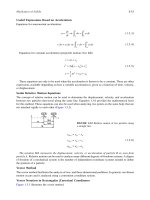
Mathematical techniques allow us to quantify total displacement caused by all vibra-
tions, to convert the displacement measurements to velocity or acceleration, to sepa-
rate these data into their components through the use of FFT analysis, and to
determine the amplitudes and phases of these functions. Such quantification is neces-
sary if we are to isolate and correct abnormal vibrations in machinery.
P
ERIODIC MOTION
Vibration is a periodic motion, or one that repeats itself after a certain interval of time
called the period, T. Figure 3.1 illustrated the periodic motion time-domain curve of a
steam turbine bearing pedestal. Displacement is plotted on the vertical, or Y-axis, and
time on the horizontal, or X-axis. The curve shown in Figure 3.4 is the sum of all
vibration components generated by the rotating element and bearing-support structure
of the turbine.
Harmonic Motion
The simplest kind of periodic motion or vibration, shown in Figure 3.2, is referred to
as harmonic. Harmonic motions repeat each time the rotating element or machine
component completes one complete cycle.
The relation between displacement and time for harmonic motion may be expressed by:
ωt
X
=
X
0
sin ()
The maximum value of the displacement is X
0
, which is also called the amplitude.
The period, T, is usually measured in seconds; its reciprocal is the frequency of the
vibration, f, measured in cycles-per-second (cps) or Hertz (Hz).
17
01.Mobley.1-6 Page 18 Friday, February 5, 1999 9:44 AM
18 Vibration Fundamentals
Figure 5.1 Illustration of vibration cycles.
1
f =
T
Another measure of frequency is the circular frequency, ω, measured in radians per sec-
ond. From Figure 5.1, it is clear that a full cycle of vibration (ωt) occurs after 360 degrees
or 2π radians (i.e., one full revolution). At this point, the function begins a new cycle.
ω = 2πf
For rotating machinery, the frequency is often expressed in vibrations per minute
(vpm) or