OPTICAL COATINGS AND THERMAL NOISE IN PRECISION MEASUREMENT pot
Bạn đang xem bản rút gọn của tài liệu. Xem và tải ngay bản đầy đủ của tài liệu tại đây (9.5 MB, 342 trang )
OPTICAL COATINGS AND THERMAL NOISE IN
PRECISION MEASUREMENT
Thermal noise from optical coatings is a growing area of concern, and overcoming limits
to the sensitivity of high-precision measurements by thermal noise is one of the greatest
challenges faced by experimental physicists.
In this timely book, internationally renowned scientists and engineers examine our
current theoretical and experimental understanding. Beginning with the theory of thermal
noise in mirrors and substrates, subsequent chapters discuss the technology of depositing
coatings and state-of-the-art dielectric coating techniques used in precision measurement.
Applications and remedies for noise reduction are also covered.
Individual chapters are dedicated to specific fields where coating thermal noise is a
particular concern, including the areas of quantum optics/optomechanics, gravitational
wave detection, precision timing, high-precision laser stabilization via optical cavities, and
cavity quantum electrodynamics. While providing full mathematical detail, the text avoids
field-specific jargon, making it a valuable resource for readers with varied backgrounds in
modern optics.
Gregory Harry has worked in the field of gravitational wave detection for over 15
years and is currently the Optics Chair and Coating Cognizant Scientist for the Laser Inter-
ferometer Gravitational Wave Observatory (LIGO), and Professor at American University,
Washington DC. He is amongst the pioneers of coating thermal noise research.
Timothy P. Bodiya is a graduate student at the Physics Department of Massachusetts
Institute of Technology. He is conducting research in the field of gravitational wave physics
and quantum optomechanics with the goal of measuring quantum effects on everyday-sized
objects (gram to kilogram size).
Riccardo DeSalvo is Professor at the University of Sannio in Benevento, Italy.
Previously he has held the positions of Senior Staff Scientist at LIGO, Caltech, Passadena,
and that of Staff Scientist at INFN in Pisa, Italy. He is a member of ASME, APS, and SIF
and has authored more than 200 refereed papers.
OPTICAL COATINGS AND
THERMAL NOISE IN
PRECISION MEASUREMENT
Edited by
GREGORY HARRY
American University, Washington DC
TIMOTHY P. BODIYA
Massachusetts Institute of Technology
and
RICCARDO DESALVO
Universit
´
a degli Studi del Sannio, Benevento, Italy
cambridge university press
Cambridge, New York, Melbourne, Madrid, Cape Town,
Singapore, S
˜
ao Paulo, Delhi, Tokyo, Mexico City
Cambridge University Press
The Edinburgh Building, Cambridge CB2 8RU, UK
Published in the United States of America by Cambridge University Press, New York
www.cambridge.org
Information on this title: www.cambridge.org/9781107003385
C
Cambridge University Press 2012
This publication is in copyright. Subject to statutory exception
and to the provisions of relevant collective licensing agreements,
no reproduction of any part may take place without the written
permission of Cambridge University Press.
First published 2012
Printed in the United Kingdom at the University Press, Cambridge
A catalogue record for this publication is available from the British Library
Library of Congress Cataloging in Publication data
Optical coatings and thermal noise in precision measurement / edited by Gregory M. Harry,
Timothy Bodiya and Riccardo DeSalvo.
p. cm.
Includes bibliographical references.
ISBN 978-1-107-00338-5 (hardback)
1. Optical coatings. 2. Quantum optics. 3. Light – Scattering. 4. Electromagnetic waves – Scattering.
I. Harry, Gregory M., 1967– II. Bodiya, Timothy P. III. DeSalvo, Riccardo.
TS517.2.O64 2012
621.36 – dc23 2011039977
ISBN 978-1-107-00338-5 Hardback
Cambridge University Press has no responsibility for the persistence or
accuracy of URLs for external or third-party internet websites referred to in
this publication, and does not guarantee that any content on such websites is,
or will remain, accurate or appropriate.
Contents
List of contributors page vii
Foreword xi
Preface xiii
1 Theory of thermal noise in optical mirrors 1
y. levin
2 Coating technology 6
s. chao
3 Compendium of thermal noises in optical mirrors 20
v. b. braginsky, m. l. gorodetsky, and s. p. vyatchanin
4 Coating thermal noise 31
i. martin and s. reid
5 Direct measurements of coating thermal noise 55
k. numata
6 Methods of improving thermal noise 73
s. ballmer and k. somiya
7 Substrate thermal noise 93
s. rowan and i. martin
8 Cryogenics 108
k. numata and k. yamamoto
9 Thermo-optic noise 129
m. evans and g. ogin
10 Absorption and thermal issues 145
p. willems, d. j. ottaway, and p. beyersdorf
11 Optical scatter 163
j. r. smith and m. e. zucker
v
vi Contents
12 Reflectivity and thickness optimization 173
i. m. pinto, m. principe, and r. desalvo
13 Beam shaping 196
a. freise
14 Gravitational wave detection 216
d. j. ottaway and s. d. penn
15 High-precision laser stabilization via optical cavities 237
m. j. martin and j. ye
16 Quantum optomechanics 259
g. d. cole and m. aspelmeyer
17 Cavity quantum electrodynamics 280
t. e. northup
References 296
Contributors
Markus Aspelmeyer
University of Vienna, Faculty of Physics, Boltzmanngasse 5, VIENNA 1090, Austria
Stefan Ballmer
Syracuse University, New York, Department of Physics, SYRACUSE, NY 13244, USA
Peter Beyersdorf
San Jose State University, Department of Physics and Astronomy, 1, Washington Square,
SAN JOSE, CA 95192-0160, USA
Vladimir B. Braginsky
M. V. Lomonosov Moscow State University, Faculty of Physics, Leninskie Gory,
MOSCOW 119991, Russia
Shiuh Chao
National Tsing Hua University, Institute of Photonics Technologies, 101 Kuangfu Rd,
Sec. 2, HSINCHU, Taiwan
Garrett D. Cole
University of Vienna, Faculty of Physics, Boltzmanngasse 5, VIENNA 1090, Austria
Riccardo DeSalvo
Universit
´
a degli Studi del Sannio, Via Port’Arsa, 11, 82100 Benevento, Italy
Matthew Evans
Massachusetts Institute of Technology, LIGO Laboratory MIT, NW22-295,
CAMBRIDGE, MA 02139, USA
Andreas Freise
University of Birmingham, School of Physics and Astronomy, Edgbaston,
BIRMINGHAM B15 2TT, UK
vii
viii List of contributors
Michael L. Gorodetsky
M. V. Lomonosov, Moscow State University, Faculty of Physics, Leninskie Gory,
MOSCOW 119991, Russia
Yuri Levin
Leiden Observatory, Niels Bohrweg 2, LEIDEN 2300 RA, The Netherlands
Iain Martin
University of Glasgow, Department of Physics and Astronomy, GLASGOW G12 8QQ,
UK
Michael J. Martin
University of Colorado, Boulder, JILA 440 UCB, BOULDER, CO 80309-0440, USA
Tracy E. Northup
Universit
¨
at Innsbruck, Institut f
¨
ur Experimentalphysik, Technikerstrasse 25/4,
INNSBRUCK 6020, Austria
Kenji Numata
NASA-Goddard Space Flight Center Code 663, 8800 Greenbelt Rd, GREENBELT, MD
20771, USA
Greg Ogin
California Institute of Technology, LIGO Laboratory, MS 100-36, Room 252B W. Bridge,
PASADENA, CA 91125, USA
David J. Ottaway
University of Adelaide, School of Chemistry and Physics, ADELAIDE, SOUTH
AUSTRALIA 5005, Australia
Steven D. Penn
Hobart and William Smith Colleges, Department of Physics, 300 Pulteney Street,
GENEVA, NY 14456, USA
Innocenzo M. Pinto
University of Sannio, Department of Engineering, Corso Garibaldi 107, Pal. dell’Aquila
Bosco-Lucarelli, BENEVENTO I-82100, Italy
Maria Principe
Department of Engineering, Corso Garibaldi 107, Pal. dell’Aquila Bosco-Lucarelli,
BENEVENTO I-82100, Italy
List of contributors ix
Stuart Reid
University of Glasgow, Department of Physics and Astronomy, GLASGOW G12 8QQ,
UK
Sheila Rowan
University of Glasgow, School of Physics and Astronomy, GLASGOW G12 8QQ, UK
Joshua R. Smith
Cal State Fullerton, Department of Physics, 800 N State College Blvd, FULLERTON, CA
92831, USA
Kentaro Somiya
Waseda Institute for Advanced Study, 1-6-1 Nishiwaseda, Shinjuku, TOKYO 169-8050,
Japan
Sergey P. Vyatchanin
M. V. Lomonosov, Moscow State University, Faculty of Physics, Leninskie Gory,
MOSCOW 119991, Russia
Phil Willems
California Institute of Technology, LIGO Laboratory, MS 18-34, PASADENA, CA
91125, USA
Kazuhiro Yamamoto
Leibniz Universitaet Hannover, Max-Planck-Institut fuer Gravitationsphysik,
Callinstrasse 38, HANNOVER D-30167, Germany
Jun Ye
University of Colorado, Boulder, JILA 440 UCB, BOULDER, CO 80309-0440, USA
Michael E. Zucker
Massachusetts Institute of Technology, LIGO Laboratory, NW22-295, 185 Albany Street,
CAMBRIDGE, MA 02139, USA
Foreword
As Lord Kelvin was renowned for saying – “to measure is to know” – and indeed pre-
cision measurement is one of the most challenging and fundamentally important areas of
experimental physics.
Over the past century technology has advanced to a level where limitations to preci-
sion measurement systems due to thermal and quantum effects are becoming increasingly
important. We see this in experiments to test aspects of relativity, the development of more
precise clocks, the measurement of the Gravitational Constant, experiments to set limits on
the polarisation of the vacuum, and the ground based instruments developed to search for
gravitational radiation.
Many of these experimental areas use laser interferometry with resonant optical cavities
as short term length or frequency references, and thermal fluctuations of cavity length
present a real limitation to performance. This has received particular attention from the
community working on the upgrades to the long baseline gravitational wave detectors,
LIGO, Virgo and GEO 600, the signals from all likely sources being at a level where
very high strain sensitivity – of the order of one part in 10
23
over relevant timescales – is
required to allow a full range of observations. Research towards achieving such levels of
strain measurement has shown that the thermal fluctuations in the length of a well designed
resonant cavity are currently dominated by those due to mechanical losses in the dielectric
materials used to form the multi-layer mirror coating used, with the fluctuations of the
mirror substrate materials also playing an important part.
Now that the importance of thermal noise in coatings and substrates is of clear importance
in a range of precision experiments using optical cavities, it is very timely that a book be
dedicated to these issues, and that the theoretical and experimental physicists at the forefront
of their field from many laboratories around the world, have collaborated together in writing
this.
The book is unique in that it ranges from discussions of the theoretical basis of thermal
noise in mirrors and substrates, through the technology of depositing coatings and the
techniques for measuring mechanical loss and thermal noise to the importance of this noise
source in a range of applications. The real challenge of bringing this about will become
xi
xii Foreword
very clear to the reader as will the rewards to be gained in areas such as precision timing
and gravitational wave detection, these areas being well described by another quotation of
Lord Kelvin – “When you are face to face with a difficulty, you are up against a discovery.”
Professor James Hough, Kelvin Professor of Natural Philosophy,
University of Glasgow, January 2011
Preface
Dedicated to Robert Kirk Burrows
In 1999, I was a young postdoc moving to Syracuse University to work on LIGO, which
had been a dream of mine since I was first introduced to gravitational wave detection as
an undergraduate in Kip Thorne’s class at Caltech. I had done my PhD in gravitational
wave detection, but using the older technology of resonant masses rather than LIGO’s laser
inteferometry. I was concerned that my background would not prove appropriate. I soon
found a common issue, thermal noise, that I was able to focus on. Beyond just a good fit for
me, thermal noise was actually a topic in flux within LIGO at the time. A talented young
theorist at Caltech named Yuri Levin had just shown that the optical coatings on the LIGO
mirrors could well contribute much more thermal noise than anyone had anticipated. What
was missing were realistic numbers to plug into Yuri’s formulas to see just how big of an
impact coating thermal noise might have. This became one of my principal roles in LIGO,
as part of a group of experimentalists interested in this question at Stanford, Glasgow, as
well as Syracuse and other collaborating institutions.
Since then, we in LIGO have found that coating thermal noise is a very important limit
to sensitivity, and we have engaged in over a decade of theoretical, experimental, and
modeling work to better understand and reduce it. One of the key difficulties was that
we had to engage coating thermal noise within the strict limits of optical performance, as
LIGO coatings also have to satisfy some of the strictest specifications on optical absorption,
scatter, uniformity on a large scale, and other more conventional optics concerns. In the
last few years, I started to see that other precision measurement fields were also hitting the
same coating thermal noise limit.
Collaboration between fields on coating thermal noise started with a discussion in a
bar in Harvard Square between myself and Markus Aspelmeyer, having been introduced
by Professor Nergis Mavalvala whose research interests overlap with both of ours. I saw
that a workshop on coating thermal noise involving r esearchers from many precision
measurements fields as well as coating technologists, optical engineers, and others could
be mutually beneficial. We held this workshop in March of 2008, and it is still accessible
on the web at />xiii
xiv Preface
Finally, this book came out of late night conversations with my graduate school roommate
and friend, Kirk Burrows, during our annual vacations on North Carolina’s Outer Banks.
He would always encourage me to write a book, so after the workshop had proved a success
and the opportunity with Cambridge University Press presented itself, I decided the time
was right. All of us who have worked to make this book happen hope it proves valuable
to both those currently in the trenches battling coating thermal noise and all the other
coating issues discussed herein, but also to researchers in new fields just coming up to these
limitations.
This book, like any book, is the result of many people’s hard work, inspiration, dedica-
tion, and collaboration. The editors and authors would like to especially thank Matt Aber-
nathy, Juri Agresti, Warren Anderson, Craig Benko, Eric Black, Birgit Brandst
¨
atter, Aidan
Brooks, Gianpietro Cagnoli, Christof Comtet, Rand Danenberg, Carly Donahue, Raffaele
Flaminio, Ray Frey and the entire LIGO Scientific Collaboration Publication and Presen-
tation Committee, Daniel Friedrich, Peter Fritschel, Eric Gustafson, Ramin Lalezari, Yige
Lin, Jean-Marie Mackowski, Andrew McClung, John Miller, Nazario Morgado, Mark Not-
cutt, Laurent Pinard, Takakazu Shintomi, David Shoemaker, Matthew Swallows, Toshikazu
Suzuki, Takashi Uchiyama, Akira Villar, Stephen Webster, Valerie Williams, Dal Wilson,
Hiro Yamamoto, and the post-graduate class in Advanced Electromagnetics at the Univer-
sity of Sannio for useful input and feedback on chapter drafts. Some material in this book
is based upon work supported by the United States National Science Foundation under
grants 0757058 and 0970147. Any opinions, findings, and conclusions expressed in this
material are those of the authors and do not necessarily reflect the views of the National
Science Foundation. We would also like to thank the Italian National Institute for Nuclear
Physics (INFN) for financial support.
1
Theory of thermal noise in optical mirrors
yuri levin
1.1 Introduction
Mechanical and optical thermal noises play an important role in many precise optome-
chanical experiments, in which positions of test bodies are monitored by laser beams.
Much of the initial experimental and theoretical research in this area was driven by the
physics of gravitational-wave interferometers, where thermal fluctuations are expected to
be the dominant source of noise in the frequency band between about 10 and 100 Hz
(Harry et al., 2002) (see Chapter 14). Recently, it has become clear that controlling ther-
mal noise will be key in several other fields, notably in designing laser cavities with
higher frequency stability (Numata et al., 2004) (see Chapter 15), in reaching the quantum
limit in macroscopic opto-mechanical experiments (Kippenberg and Vahala, 2008) (see
Chapter 16), and in cavity QED experiments (Miller et al., 2005) (see Chapter 17). In this
chapter we review the statistical-mechanics formalism which is used to theoretically calcu-
late mechanical and optical thermal noise. For completeness, we also add a discussion of
another important limitation in mechanical measurements, the so-called Standard Quantum
Limit.
1.2 Theory of mechanical thermal noise
The theory of time-dependent thermodynamical fluctuations has been extensively devel-
oped for the past century. One of the fundamental results in this field is the Fluctuation–
Dissipation Theorem, which was originally formulated by Callen and Welton (1951).
Callen and Welton’s insight was that the intensity of random fluctuation in some macro-
scopic degree of freedom
ˆ
x of the thermodynamic system was proportional to the strength
with which
ˆ
x was coupled to the microscopic degrees of freedom of the heat bath. Since
the same coupling is responsible for damping of motion in
ˆ
x, one obtains a proportionality
relation between the microscopic thermal fluctuations of the quantity
ˆ
x and the damping
coefficient for the macroscopic motion when
ˆ
x is driven externally. For optomechanical
Optical Coatings and Thermal Noise in Precision Measurement, eds. Gregory M. Harry, Timothy Bodiya and Riccardo DeSalvo.
Published by Cambridge University Press. © Cambridge University Press 2012.
1
2 Y. L ev in
experiments,
ˆ
x is typically an integrated quantity over a mirror surface. For example, in
experiments with a test mass position readout by a laser,
ˆ
x, is given by
ˆ
x =
f (r)x(r,t)d
2
r. (1.1)
Here r is the location of a point on the test-mass’ mirror surface, and x(r, t ) is the dis-
placement of the mirror along the direction of the laser beam at point r and time t.
The form factor f (r) depends on the laser beam profile and is proportional to the laser
light intensity at the point r (Gillespie and Raab, 1995); it is usually normalized so that
f (r)d
2
r = 1.
The Fluctuation–Dissipation Theorem is then applied to the variable
ˆ
x by performing a
mental experiment (Levin, 1998) consisting of the following three steps.
r
Apply an oscillatory pressure P (r,t) = F
0
cos(2πf t)f (r) to the face of the test mass.
This is equivalent to driving the system with an external interaction Hamiltonian H
int
=
−F
0
cos(2πf t)
ˆ
x.
r
Work out the average power, W
diss
, dissipated in the test mass under the action of this
oscillatory pressure.
r
Compute the spectral density of fluctuations in
ˆ
x from
S
ˆ
x
(f ) =
2k
B
T
π
2
f
2
W
diss
F
2
0
, (1.2)
where k
B
and T are the Boltzmann’s constant and the temperature of the mirror respec-
tively, and f is the frequency at which the spectral density is evaluated.
This method is straightforward to use. Once the dissipative processes are understood, the
calculation reduces to a problem in elasticity theory (Levin, 1998; Bondu et al., 1998) and,
in the case of thermoelastic noise (see Section 1.3 and Chapter 9), time-dependent heat
flow (Braginsky et al., 1999; Liu and Thorne, 2000). For the important case of so-called
structural damping (Saulson, 1990),
W
diss
= 2πf U
max
φ(f ), (1.3)
where U
max
is the energy of elastic deformation at a moment when the test mass is maximally
contracted or extended under the action of the oscillatory pressure, and φ(f )istheloss
angle characterising the dissipation. If the frequency band being measured is well below
the normal modes of the test mass (as is often the case in gravitational wave detectors,
see Chapter 14, frequency stabilization, see Chapter 15, and cavity QED experiments,
see Chapter 17) one can assume constant, non-oscillating pressure P (r) = F
0
f (r) when
evaluating U
max
. On the other hand, in many microscopic opto-mechanical experiments
the detection frequencies are comparable to mechanical resonance frequencies, such as
discussed in Chapter 16, and one needs to solve a time-dependent elasticity problem in
order to find U
max
.
Theory of thermal noise in optical mirrors 3
For the case of structural damping, and for frequencies much smaller than the mechanical
resonant frequencies of the system, the thermal noise is approximately given by (Harry et al.,
2002)
S
ˆ
x
=
2k
B
T
√
π
3
f
1 − σ
2
Yw
m
φ
substrate
(f ) +
1
√
π
d
w
m
Aφ
coating
(f )
, (1.4)
where
A =
Y
2
(1 + σ )
2
(1 − 2σ )
2
+ Y
2
(1 + σ
)
2
(1 − 2σ
)
YY
(1 − σ
2
)(1 − σ
2
)
. (1.5)
Here Y and Y
are the Young’s moduli of the substrate and coating, respectively, σ and
σ
are their Poisson’s ratios, d is the coating thickness, w
m
is the radius where the field
amplitude of the Gaussian laser beam is 1/e, and φ
substrate
and φ
coating
are the loss angles of
the substrate and the coating, respectively. This expression is valid when the beam size w
m
is much smaller than the size of the mirror. When the latter approximation breaks down,
one can find a series solution (Bondu et al., 1998; Liu and Thorne, 2000) or an analytical
solution for the coating thermal noise contribution (Somiya and Yamamoto, 2009) for
axisymmetric configurations and use direct finite-element methods to calculate U
max
for
cases without the axial symmetry (Numata, 2003). See also Chapter 4.
Of the two contributions on the right-hand side of Equation 1.4, the one from the coating
is projected to be the greater in most precision experiments. There are two essential reasons
why the contribution from the coating is so large. The first one is geometrical: the sources
of thermodynamically fluctuating random stress are spread out throughout the substrate
and the coating, but the ones near the coating are closer to the surface and thus have greater
effect on its displacement. This geometrical effect explains why the coating noise scales
as 1/w
2
m
while the structural substrate noise scales as 1/w
m
(Levin, 1998). The second
reason is that coating losses per volume are typically orders of magnitude greater than that
of the substrates (see Chapters 4 and 7). Several practical proposals on how to reduce the
unfavorable geometric factor have been investigated. The basic idea behind these proposals
is to either increase the effective beam size by reconfiguring its shape towards a flat-top
geometry or by working with higher-order cavity modes, see Chapter 13. Decreasing the
mechanical loss of the coating is a great challenge in thermal noise research, and is discussed
in Chapter 4. Other ideas for improving coating thermal noise are discussed in Chapters 6
and 8.
1.3 Theory of optical thermal noise
So far we have described mechanical thermal noise which appears due to small thermally
driven random changes of the mirror’s shape and results in random displacement of the mir-
ror’s surface. However, this description is not complete. Upon striking the mirror surface,
the light penetrates several wavelengths into the coating, before being completely reflected.
4 Y. L evi n
The temperature within this skin layer of the coating is not constant, but fluctuates ther-
modynamically. These temperature fluctuations lead to random changes in the phase of the
reflected light via two physical effects.
r
The mirror surface shifts randomly due to the coating’s thermal expansion. This is known
as the coating thermoelastic noise (Braginsky and Vyatchanin, 2003a; Fejer et al., 2004),
and
r
The optical pathlength inside the coating changes randomly, due to the temperature
dependence of the coating’s index of refraction. This is known as the thermorefractive
noise (Braginsky et al., 2000).
The thermorefractive and thermoelastic noises are typically anti-correlated, which
reduces their impact on noise (Evans et al., 2008; Gorodetsky, 2008) and are discussed in
detail in Chapter 9 (see also Section 6.6). The theoretical evaluation of both of these noises
involves calculating the spectra of thermal fluctuations of temperature-dependent quantities
of the form
δ
ˆ
T (t) =
q(r)δT (r,t)d
3
r. (1.6)
Here δT (r,t) is the local fluctuation in temperature and q(r) is the form factor proportional
to the local intensity of light and the thermo-refractive coefficient ∂n/∂T. A variation of
the Fluctuation–Dissipation Theorem has been devised that allows one to calculate directly
the spectral density S
ˆ
T
(f ) (Levin, 2008). The calculation proceeds via a mental experiment
similar to the one in the previous section. It consists of the following three steps.
r
Periodically inject entropy into the medium, with the volume density of the entropy
injection given by
δs(r)
dV
= F
0
cos(2πf t)q(r), (1.7)
where F
0
is an arbitrarily small constant.
r
Track all thermal relaxation processes in the system (e.g. the heat exchange between
different parts of the system) which occur as a result of the periodic entropy injection.
Calculate the total entropy production rate and hence the total dissipated power W
diss
which occurs as a result of the thermal relaxation.
r
Evaluate the spectral density of fluctuations in δ
ˆ
T from
S
ˆ
x
(f ) =
2k
B
T
π
2
f
2
W
diss
F
2
0
. (1.8)
This formalism was instrumental in the calculation of total thermo-optical coating
noise (Evans et al., 2008). It is likely to be useful for computing thermorefractive noise in
experiments with non-trivial optical geometry, see Benthem and Levin (2009) for example.
Theory of thermal noise in optical mirrors 5
1.4 Standard quantum limit
There is another source of noise which places an important limitation on opto-mechanical
experiments. From the early days of quantum mechanics, it was clear that by precise
measurement of a test mass’ position one inevitably, and randomly, perturbs its momentum
in accordance with the Heisenberg uncertainty relation p ≥ ¯h/(2x). Thus no matter
which measurement device one uses, one inevitably introduces a back-action noise into
the system; the higher the intrinsic precision of the measuring device, the greater the back-
action noise. One can express this mathematically via the uncertainty relation (Braginsky
and Khalili (1992))
S
x
(f )S
F
(f ) −|S
xF
(f )|
2
≥ ¯h
2
/4, (1.9)
where S
x
(f ) is the spectral density of the intrinsic measurement noise, S
F
(f ) is the spectral
density of the back-action noise, and S
xF
(f ) is the spectral density of the correlation
between the measurement error and the back-action perturbation. For a vast majority of
measuring devices the cross-correlation term S
xF
is zero. Then the intrinsic and back-action
noises, added in quadrature, enforce a limit on how precisely the position of a test-mass can
be monitored. This is known as the standard quantum limit (SQL) (Braginsky and Khalili
(1992) and references therein). For a free test body of mass m, the SQL is given by
S
SQL
x
(f ) =
¯h
m(2πf )
2
. (1.10)
As the coating noise is reduced due to technological progress, precision optical experiments
will reach the SQL. However, the SQL is not a fundamental limit and can be overcome by
using techniques of quantum optics which are capable of introducing correlations between a
measurement error and a back-action perturbation, see Section 11.3 for discussion. Practical
proposals exist on how to reach sensitivities below the SQL, see Kimble et al. (2001);
Buonanno et al. (2001).
2
Coating technology
shiuh chao
2.1 Introduction
The preparation and deposition of coatings can determine many of their basic properties.
This chapter discusses the major technologies for creating thin film coatings, with an
emphasis on those technologies most useful to precision measurement applications, as a
baseline for the other chapters to expand on. There are many types of optical coatings,
but we will be concerned with stacks of multi-layer thin films of dielectric materials with
different refractive indices and thicknesses. Through optical interference effects, various
optical functions can be achieved by properly selecting the materials and designing the layer
thicknesses. Traditionally, the major application of coatings has been in imaging systems,
including coatings on lenses, windows, and filters for purposes such as anti-reflection, band
passing, polarization selection, etc. (Macleod, 2010; Baumeister, 2004a). With the advent
of the laser and its diverse applications, high quality coatings for laser optics have become
in high demand. Dielectric mirror coatings, which are often used in active or passive optical
cavities, are particularly important.
The dielectric mirror is composed of a stack of thin films with pairs of alternating high
and low refractive index materials. Conventionally, each layer has a quarter wave of optical
thickness. Optical thickness is defined as d
opt
= dn, where d is the physical thickness of the
layer, and n is the refractive index of the coating material. Given this, a quarter wave layer
has d
opt
/λ = 1/4, where λ is the wavelength of light for which the coating is designed.
Reflectance of the mirror increases with the increasing number of pairs and the increasing
refractive index difference between the pair materials in general. For a quarter wave stack,
the reflectivity in air at normal incidence can be found from
r =
1 − n
s
(
n
1
/n
2
)
2p
1 + n
s
(
n
1
/n
2
)
2p
, (2.1)
where r is the reflected field amplitude, n
s
is the refractive index of the substrate, n
1
and
n
2
are the refractive indices of the two coating materials, and p is the number of pairs of a
high and low index material in the coating.
Optical Coatings and Thermal Noise in Precision Measurement, eds. Gregory M. Harry, Timothy Bodiya and Riccardo DeSalvo.
Published by Cambridge University Press. © Cambridge University Press 2012.
6
Coating technology 7
High-end applications for the mirror coatings all require that the coatings have low
optical losses, i.e. low absorption (see Chapter 10) and low scattering (see Chapter 11). In a
ring laser gyroscope, for example, extremely low backscattering (typically less than a few
ppm) in the mirror is required in order to avoid frequency lock-in so that low rotation rates
can be detected (Kalb, 1986). Furthermore, some additional applications now require low
thermal noise (see Chapter 5, 14–17). Beginning in the 1970s, researchers also intensively
studied laser induced damage stemming from optical coating losses in high energy laser
applications, such as laser ignition fusion (Stolz and Taylor, 1992).
In addition to low optical losses, narrow-band thin film filters composed of multiples of
half-wavelength thick films in between quarter wave stacks are required to have a narrow
pass-band width as low as sub-nm and to be environmentally stable while operating in the
field. These types of filters are critical for dense wavelength division multiplexing (DWDM)
technology in optical communication. These criteria impose high thickness control and
environmental stability requirements on the coatings (Takashashi, 1995). The stringent
requirements of high-end applications drove rapid progress in optical coating technology
since the 1970s. This chapter introduces coating methods, coating processes, and thin film
materials used in high-end coating technologies with the purpose of stimulating further
research and development activities on coatings for precision measurement.
2.2 Coating methods
Various coating methods have been developed to provide films with desired qualities such
as good optical characteristics, uniformity, precise thickness control, absence of stress and
defects, strong adhesion, ease of fabrication, large throughput, and low fabrication cost.
Among the many factors that affect the film qualities, one of fundamental importance is
the kinetic energy of the coating material atoms when impinging on the substrate prior to
condensation. Upon arriving at the substrate surface, the atoms need a sufficient amount of
energy to overcome the activation energy of various mechanisms to reach proper sites for
nucleation and growth. This will allow for a close-packed structure and good adhesion to
the substrate and the neighboring layer (Neugebauer, 1970; Ohring, 2002). In the following
sections, we shall introduce different coating methods, with emphasis on energetics.
2.2.1 Thermal evaporation
Thermal evaporation is the most commonly used coating method. Source material is heated
by resistance heating or by electron beam bombardment to either the sublimation or melting
point. The evaporants then condense on the substrate to form a thin film. Most compounds
do not evaporate to form films that have the same composition as the source material, and
various means for reactive evaporation or multiple single element source co-evaporations
need to be implemented to insure the correct stoichiometry for the films. The average kinetic
energy of the evaporant when impinging the substrate is the thermal energy at the melting
8 S. Chao
point, typically of the order of 10
−1
eV. This is a relatively low energy and therefore the
atoms have difficulty migrating on the substrate surface and forming a dense, less porous
film. The film is therefore susceptible to moisture when exposed to the atmosphere, which
can lead to weak adhesion to the substrate and a low refractive index.
There are many methods to increase the energy of the evaporant (Vossen and Kern, 1978);
substrate heating, DC or RF biasing of the substrate, and more recently employed, ion beam
assisted deposition (IBAD). IBAD uses a low energy and high current broad ion beam to
bombard the substrate, assisting the film formation with denser packing and enhanced
oxidation/nitridation when the ion beam contains oxygen/nitrogen ions for deposition of
oxide/nitride films (Green et al., 1989). Since the evaporation process i s performed in a high
vacuum, typically 10
−6
Torr, the mean free path of the evaporant is a few tens of meters.
The evaporant distribution is nearly Lambertian; the evaporant has a large field of view.
In addition, a high evaporation rate is easy to achieve by increasing the temperature of
the melt with electron beam bombardment. Therefore, high throughput deposition can be
realized in a large box coater that can accommodate a large quantity of substrates positioned
in planetary rotation dome-shaped holders. Currently, electron beam evaporation with the
IBAD method is the primary coating technique for large quantities of fairly good quality
batched optical coatings.
2.2.2 Glow discharge sputtering
The glow discharge sputter deposition technique dates back to the nineteenth century,
when deposits of cathode material were observed in DC glow discharge environments.
In a straightforward planar DC glow discharge, the t arget serves as the cathode and the
substrate serves as the anode. At the state of “abnormal glow” for sputtering, most of the
discharge voltage falls in the Crookes dark space adjacent to the cathode. The positive ions
in the neighboring negative glow region gain kinetic energy, typically a few hundreds to
1000 eV, from the cathode fall and bombard the cathode to sputter off the cathode atoms.
The sputtered atoms have kinetic energy of a few tens of eV (see Section 2.2.3). Initiating
voltage for the glow discharge varies with the product of the gas pressure and the electrode
separation with a deep minimum according to Paschen’s law, which limits the operating
gas pressure and electrode separation. A typical value for electrode separation is a few cm
and for gas pressure is in the range of 10
−2
Torr. This is a relatively high pressure and
the mean free path of the sputtered atoms is therefore short. The consequence is that the
kinetic energy of the sputtered atoms tends to be thermalized through multiple collisions
on the way to the substrate. A typical value for the kinetic energy of the sputtered atoms
when impinging the substrate is on the order of 1 eV, which is lower than that in ion beam
sputtering (see Section 2.2.3) but about ten times higher than that of the evaporation process.
Therefore, film qualities of adhesion, density, refractive index, and moisture susceptibility
are generally better than that of the films deposited by thermal evaporation. Nevertheless,
since the substrate is immersed in plasma during deposition, the films may be subjected to
UV damage and re-sputter.
Coating technology 9
Both triode sputter, in which a thermionic electrode is added to the diode, and magnetron
sputter, in which a magnetic field is applied to confine the plasma, can increase the collision
probability between the electron and the gas atoms to enhance the plasma generation
efficiency. This allows lower gas pressure, lower power or larger electrode distance to
be accommodated. When the sputter target is an electrical insulator, a radio frequency
(13.56 MHz) source is applied. The heavier ion is less responsive to the high frequency RF
field than the electrons in the plasma, establishing a self-bias at the target for sputtering.
One advantage of glow discharge sputtering is that very large targets can be used, such that
large substrates, e.g. architectural window glass, solar panels, display panels, plastic rolls,
etc, can be coated in a load-lock conveyer-fed coater or a web-coater for uninterrupted
continuous large volume coating operations.
2.2.3 Ion beam sputter deposition (IBSD)
Most of the optical coatings for high-end applications mentioned in Section 2.1 are fab-
ricated by the ion beam sputter deposition method (IBSD). The ion beam source was
originally used as a spacecraft thruster, only later was it applied to ion etching and thin film
deposition. In recent years, the focused ion beam (FIB) technique has been developed for
semiconductor device fabrication, diagnosis, and nano-patterning (Joe et al., 2009). Wei
and Louderback (1979) first used the IBSD technique to sputter deposit mirrors for a ring
laser gyroscope, obtaining unprecedented quality. The technique then became the major
coating method for high quality optical coatings.
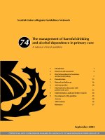
The schematic of an IBSD apparatus with a conventional Kaufman type ion source, i.e.
hot filament with extracting grids, is shown in Figure 2.1. High density plasma is generated
in the discharge chamber and ion beamlets are extracted, accelerated through the apertures
in the grids to form a broad ion beam, and hit the target. The target atoms are, then, sputtered
off and condense on the substrate to form the films. Several targets can be attached to the
rotatable target holder for coating multi-layers. Planetary rotation fixtures can be used to
obtain films with uniform thickness distribution.
Ion source
The conventional ion beam generation method is the use of the Kaufman type ion source.
Referring to Figure 2.1, electrons emitted from the hot cathode through thermionic emission
collide with gas atoms, typically argon gas, to produce positive ions and electrons. The
ionization energy for argon is 15.76 eV, and around a 40 V voltage difference between the
cathode and the anode with a few mTorr of gas pressure is sufficient to sustain the plasma.
The anode is typically held at a voltage from 500–1000 V above ground, and the plasma
potential is nearly the same value. The target is held at the ground potential. The average
kinetic energy of the ions is therefore 500–1000 eV when hitting the target. The screen grid
is held to roughly the anode potential and the accelerator grid is negatively biased to about
−100 V. Both grids are precisely aligned to each other so that ion beamlets are extracted
10 S. Chao
Figure 2.1 Schematics of an ion beam sputter setup.
and accelerated through the apertures. Factors such as grid separation, aperture size, grid
curvature, applied voltage, plasma density, etc, affect the beam shape, beam divergence and
the current density. Thorough reviews for the physics and characteristics of the Kaufman
ion source are given in Kaufman et al. (1982); Harper et al. (1982). The grids are made
of graphite or molybdenum, which have higher resistance to ion bombardment within the
aperture. A plasma bridge neutralizer, usually a thermionic cathode or a hollow cathode
which emits electrons to neutralize the ion beam for sputtering the insulator targets, is
positioned aside the beam path. For depositing oxide films, oxygen gas with pressure around
10
−4
–10
−5
Torr is fed into the sputter chamber to oxidize the films during deposition. A
second ion source is sometimes used to bombard the substrate for ion beam assisted sputter
deposition. The second ion source is generally low energy and high current so that the film
will not be re-sputtered and yet sufficient energy can be added to assist film growth. The
second ion beam could be an oxygen ion beam or a mixture of oxygen and argon to enhance
the oxidation for the oxide film.
A major drawback to the hot filament ion source is the frequent filament maintenance
required. The filament might break down during long-term continuous deposition (e.g.
coating for DWDM filters, the filament is subjected to ion bombardment and the ion
beam may become contaminated). Two other advanced plasma generation methods have
been developed to avoid hot filament issues; radio frequency (RF) and electron cyclotron
resonance (ECR) plasma generation. RF power, with a frequency of 13.56 MHz, is fed
into the discharge chamber, usually by inductive coupling, i.e. through a solenoid coil or
a flat spiral coil that is embedded in a dielectric shield. Electrons oscillate in the RF field
Coating technology 11
and collide with the gas atoms to form plasma. In ECR plasma generation, a microwave
of 2.45 GHz is fed into the discharge chamber through an antenna shielded in a quartz
container. A static magnetic field with a strength of 856 Gauss, satisfying the electron
cyclotron resonance condition f = eB/
(
2πm
)
, is provided perpendicular to the electric
field. Electrons cycle the magnetic field lines and pick up energy resonantly from the
microwaves and make multiple collisions with the gas atoms along the way. Highly efficient
plasma generation can be achieved in a smaller discharge volume and with lower gas
pressure. Both RF and ECR plasma generation methods use the same grid configuration as
the Kaufman s ource to extract, accelerate, and focus the ion beam. Each ion source designer
typically has a unique design to achieve uniform plasma distribution, high current density,
proper energy range, good focus quality, large beam size, and low beam contamination.
The 13.56 MHz RF and 2.54 GHz microwave generations have become industry standards,
and the generators and tuning networks are readily available. However, among the different
types of ion sources, the hot filament ion source is still the least expensive choice.
Sputtering process
For depositing metal oxides or nitrides (e.g. tantala (Ta
2
O
5
), titania (TiO
2
), alumina (Al
2
O
3
),
aluminum nitride (AlN), disilicon trinitride (Si
2
N
3
)), metal targets are usually used for
their better thermal conductivity and oxygen or nitrogen gas is introduced into the sputter
chamber or discharge chamber to react with the sputtered atoms. Sputter yield, angular
distribution of the sputtered atom, and energy distribution of the sputtered atoms in the
IBSD process are major factors that affect the deposition rate, thickness uniformity, and
film quality. The following discussion is focused on polycrystalline targets as these are the
most commonly used metal targets in the IBSD process.
The ion energy for IBSD is in the range of 500–1000 eV when hitting the target. Within
this range, the ion penetration depth is only a few atomic layers (Harper, 1984). The sputter
yield, defined as the number of sputtered atoms per incident ion, is about unity for heavy
inert ions of argon, krypton, and xenon, and about 0.5 for neon and 0.01 for helium (Vossen
and Kern, 1978). Argon is therefore the most commonly used gas for IBSD due to its
high sputter yield and lower cost. The sputter yield is a function of the angle of incidence
of the ion beam. It increases with the angle of incidence to a maximum around 40–70
◦
depending on the target material, and down to zero for grazing incidence (Melliar-Smith
and Mogab, 1978). This gives a guideline for orienting the target relative to the direction
of the ion beam in the IBSD chamber. The angular distribution of the sputtered atoms is
generally “under-cosine” for a normal incident ion beam, i.e. less than the cosine distribution
around the normal direction, but it is preferentially in the forward direction for oblique ion
incidence (Wehner and Rosenberg, 1960). Therefore, in a conventional IBSD chamber, the
normal of the substrate surface is oriented perpendicularly to the direction of the ion beam
and the angle of incidence for the ion beam is about 45
◦
to the target.
The kinetic energy of the IBSD sputtered atoms has been systematically investigated only
in limited situations. It was found that the kinetic energy of the sputtered atoms from a copper