Internal Combustion Engines pot
Bạn đang xem bản rút gọn của tài liệu. Xem và tải ngay bản đầy đủ của tài liệu tại đây (15.6 MB, 243 trang )
Edited by
Kazimierz Lejda
Paweł Woś
INTERNAL COMBUSTION
ENGINES
Edited by Kazimierz Lejda and Paweł Woś
Internal Combustion Engines
Edited by Kazimierz Lejda and Paweł Woś
Contributors
Wladyslaw Mitianiec, Yoshihito Yagyu, Hideo Nagata, Nobuya Hayashi, Hiroharu Kawasaki,
Tamiko Ohshima, Yoshiaki Suda, Seiji Baba, Eliseu Monteiro, Marc Bellenoue, Julien Sottton,
Abel Rouboa, Simón Fygueroa, Carlos Villamar, Olga Fygueroa, Artur Jaworski, Hubert
Kuszewski, Kazimierz Lejda, Adam Ustrzycki, Teresa Donateo, Mudassar Abbas Rizvi, Qarab
Raza, Aamer Iqbal Bhatti, Sajjad Zaidi, Mansoor Khan, Sorin Raţiu, Corneliu Birtok-Băneasă,
Yuki Kudoh
Published by InTech
Janeza Trdine 9, 51000 Rijeka, Croatia
Copyright © 2012 InTech
All chapters are Open Access distributed under the Creative Commons Attribution 3.0 license,
which allows users to download, copy and build upon published articles even for commercial
purposes, as long as the author and publisher are properly credited, which ensures maximum
dissemination and a wider impact of our publications. After this work has been published by
InTech, authors have the right to republish it, in whole or part, in any publication of which they
are the author, and to make other personal use of the work. Any republication, referencing or
personal use of the work must explicitly identify the original source.
Notice
Statements and opinions expressed in the chapters are these of the individual contributors and
not necessarily those of the editors or publisher. No responsibility is accepted for the accuracy
of information contained in the published chapters. The publisher assumes no responsibility for
any damage or injury to persons or property arising out of the use of any materials,
instructions, methods or ideas contained in the book.
Publishing Process Manager Marina Jozipovic
Typesetting InTech Prepress, Novi Sad
Cover InTech Design Team
First published November, 2012
Printed in Croatia
A free online edition of this book is available at www.intechopen.com
Additional hard copies can be obtained from
Internal Combustion Engines, Edited by Kazimierz Lejda and Paweł Woś
p. cm.
ISBN 978-953-51-0856-6
Contents
Preface IX
Section 1 Engine Fuelling, Combustion and Emission 1
Chapter 1 Factors Determing Ignition and Efficient
Combustion in Modern Engines Operating
on Gaseous Fuels 3
Wladyslaw Mitianiec
Chapter 2 Fundamental Studies on the Chemical Changes and Its
Combustion Properties of Hydrocarbon Compounds by
Ozone Injection 35
Yoshihito Yagyu, Hideo Nagata, Nobuya Hayashi,
Hiroharu Kawasaki, Tamiko Ohshima,
Yoshiaki Suda and Seiji Baba
Chapter 3 Syngas Application to Spark Ignition Engine Working
Simulations by Use of Rapid Compression Machine 51
Eliseu Monteiro, Marc Bellenoue,
Julien Sottton and Abel Rouboa
Chapter 4 Thermodynamic Study of the Working Cycle
of a Direct Injection Compression Ignition Engine 75
Simón Fygueroa, Carlos Villamar and Olga Fygueroa
Chapter 5 The Effect of Injection Timing on the Environmental
Performances of the Engine Fueled by LPG in
the Liquid Phase 111
Artur Jaworski, Hubert Kuszewski,
Kazimierz Lejda and Adam Ustrzycki
Section 2 Engine Design, Control and Testing 131
Chapter 6 Intelligent Usage of Internal Combustion Engines
in Hybrid Electric Vehicles 133
Teresa Donateo
VI Contents
Chapter 7 Modeling and Simulation of
SI Engines for Fault Detection 161
Mudassar Abbas Rizvi, Qarab Raza,
Aamer Iqbal Bhatti, Sajjad Zaidi and Mansoor Khan
Chapter 8 The Study of Inflow Improvement in Spark Engines
by Using New Concepts of Air Filters 187
Sorin Raţiu and Corneliu Birtok-Băneasă
Chapter 9 Understanding Fuel Consumption/Economy
of Passenger Vehicles in the Real World 217
Yuki Kudoh
Preface
Internal combustion engines (ICE) are the main sources of powering for almost all
road vehicles, yet many other machines too. Being under strength development for a
number of years, they have already reached a relatively high level of technical
excellence and now they also produce acceptable output parameters. Still, they are not
devoid of drawbacks. Harmful exhaust emissions can be pointed as the most
important here. This problem is the main focus of interest for automotive researchers
and engineers. Continuous decrease of exhaust emission limits additionally intensifies
their efforts to produce more green engines and vehicles. On the other hand, rapid
development of road transportation and the growth of end-users’ demands toward
more and more comfortable, durable, reliable and fuel-saving vehicles unceasingly
calls for improvements in engine design and technology.
Despite many attempts, replacing the internal combustion engine with other, but
equally effective power source still fails. Therefore, extensive works on the
improvement of internal combustion engines should be carried out and the results
need to be widely published.
As the answer to above expectations, this book on internal combustion engines brings
out few chapters on the research activities through the wide range of current engine
issues. The first section groups combustion-related papers including all research areas
from fuel delivery to exhaust emission phenomena. The second one deals with various
problems on engine design, modeling, manufacturing, control and testing. Such
structure should improve legibility of the book and helps to integrate all singular
chapters as a logical whole.
We wish to thank InTech Publisher and are especially pleased to express same thanks
to Ms. Viktorija Žgela for giving us an invitation and opportunity to be editors of the
book on internal combustion engines. Distinctive thanks are also due to Ms. Romana
Vukelić and Ms. Marina Jozipović, and Publishing Process Staff for their help in
coordinating the reviews, editing and printing of the book.
Kazimierz Lejda and Paweł Woś
Rzeszów University of Technology,
Poland
Section 1
Engine Fuelling, Combustion and Emission
Chapter 1
Factors Determing Ignition and Efficient
Combustion in Modern Engines Operating on
Gaseous Fuels
Wladyslaw Mitianiec
Additional information is available at the end of the chapter
1. Introduction
Recently in automotive industry the applying of gaseous fuels and particularly
compressed natural gas both in SI and CI engines is more often met. However application
of CNG in the spark ignition internal combustion engines is more real than never before.
There are known many designs of the diesel engines fuelled by the natural gas, where the
gas is injected into inlet pipes. Because of the bigger octane number of the natural gas the
compression ratio of SI engines can be increased, which takes effect on the increase of the
total combustion efficiency. In diesel engines the compression ratio has to be decreased as
a result of homogeneity of the mixture flown into the cylinder. Such mixture cannot
initiate the self-ignition in traditional diesel engines because of higher value of CNG
octane number. Direct injection of the compressed natural gas requires also high energy
supplied by the ignition systems. A natural tendency in the development of the piston
engines is increasing of the air pressure in the inlet systems by applying of high level of
the turbo-charging or mechanical charging. Naturally aspirated SI engine filled by the
natural gas has lower value of thermodynamic efficiency than diesel engine. The
experiments conducted on SI engine fuelled by CNG with lean homogeneous mixtures
show that the better solution is the concept of the stratified charge with CNG injection
during the compression stroke. The presented information in the chapter is based on the
own research and scientific work partly described in scientific papers. There is a wider
discussion of main factors influencing on ignition of natural gas in combustion engines,
because of its high temperature of ignition, particularly at high pressure. The chapter
presents both theoretical considerations of CNG ignition and experimental work carried
out at different air-fuel ratios and initial pressure.
Internal Combustion Engines
4
Gas engines play more and more important role in automotive sector. This is caused by
decreasing of crude oil deposits and ecologic requirements given by international
institutions concerning to decreasing of toxic components in exhaust gases. Internal
combustion engines should reach high power with low specific fuel consumption and
indicate very low exhaust gas emission of such chemical components as hydrocarbons,
nitrogen oxides, carbon monoxide and particularly for diesel engines soot and particulate
matters. Chemical components which are formed during combustion process depend on
chemical structure of the used fuel. Particularly for spark ignition engines a high octane
number of fuel is needed for using higher compression ratio which increases the thermal
engine efficiency and also total efficiency.
2. Thermal and dynamic properties of gas fuels
The mixture of the fuel and oxygen ignites only above the defined temperature. This
temperature is called as the ignition temperature (self-ignition point). It is depended on
many internal and external conditions and therefore it is not constant value. Besides that for
many gases and vapours there are distinguished two points: lower and higher ignition
points (detonation boundary). These two points determine the boundary values where the
ignition of the mixture can follow. The Table 1 presents ignition temperatures of the
stoichiometric mixtures of the different fuels with the air.
Fuel I
g
nition tem
p
erature [C] Fuel I
g
nition tem
p
erature [C]
Gasoline 350 - 520 Brown coal 200 - 240
Benzene 520 - 600 Hard coal atomised 150 - 220
Furnace oil
340 Cokin
g
coal
250
Pro
p
ane
500 Soot 500 - 600
Charcoal 300 - 425 Natural gas
650
Butane (n) 430 Cit
y
g
as
450
Furnace oil EL 230 - 245 Coke 550 - 600
Table 1. Ignition temperatures of the fuels in the air (mean values)
The combustion mixture, which contains the fuel gas and the air, can ignite in strictly
defined limits of contents of the fuel in the air. The natural gas consists many hydrocarbons,
however it includes mostly above 75% of methane. For the experimental test one used two
types of the natural gas:
1. the certified model gas G20 which contains 100% of methane compressed in the bottles
with pressure 200 bar at lower heat value 47.2 – 49.2 MJ/m
3
2. the certified model gas G25 that contain 86% of methane and 14% of N2 at lower heat
value 38.2 – 40.6 MJ/m
3
.
The natural gas delivered for the industry and households contains the following chemical
compounds with adequate mean mass fraction ratios: methane - 0.85, ethane - 0.07, propane
- 0.04, n-butane - 0.025, isobutene - 0.005, n-pentane - 0.005, isopentane - 0.005.
Factors Determing Ignition and Efficient Combustion in Modern Engines Operating on Gaseous Fuels
5
Because the natural gas contains many hydrocarbons with changeable concentration of the
individual species the heat value of the fuel is not constant. It influences also on the ignition
process depending on lower ignition temperature of the fuel and energy induced by
secondary circuit of the ignition coil. For comparison in Table 2 the ignition limits and
temperatures for some technical gases and vapours in the air at pressure 1.013 bars are
presented. The data show a much bigger ignition temperature for the natural gas (640 – 670
°C) than for gasoline vapours (220°C). For this reason the gasoline-air mixture requires
much lower energy for ignition than CNG-air mixture. However, higher pressure during
compression process in the engine with higher compression ratio in the charged SI engine
causes also higher temperature that can induce the sparking of the mixture by using also a
high-energy ignition system. Because of lower contents of the carbon in the fuel, the engines
fuelled by the natural gas from ecological point of view emit much lower amount of CO
2
and decreases the heat effect on our earth.
Till now there are conducted only some laboratory experiments with the high-energy
ignition system for spark ignition engines with direct CNG injection. There are known the
ignition systems for low compressed diesel engines fuelled by CNG by the injection to the
inlet pipes.
Type of gas Chemical
formula
Normalized
density
(air = 1)
Ignition limits in
the air
(% volumetric)
Ignition
temperature
in the air [°C]
Gasoline ~C8H17 0.61 0.6 - 8 220
Butane (n) C4H10 2.05 1.8 – 8.5 460
Natural gas H 0.67 5 - 14 640
Natural gas L 0.67 6 - 14 670
Ethane C2H6 1,047 3 – 12.5 510
Ethylene C2H4 1,00 2.7 - 34 425
Gas propane-butane 50% 1.79 2 - 9 470
Methane CH4 0.55 5 - 15 595
Propane C3H8 1.56 2,1 – 9.5 470
City gas I 0.47 5 - 38 550
City gas II 0.51 6 - 32 550
Carbon monoxide CO 0.97 12.5 - 74 605
Hydrogen H2 0.07 4 - 76 585
Diesel oil 0.67 0.6 – 6.5 230
Table 2. Ignition limits and ignition temperatures of the most important technical gases and vapours in
the air at pressure 1,013 bar
Composition and properties of natural gas used in experimental tests are presented in Table 3.
Internal Combustion Engines
6
No Parameter
Nomenclature
or symbol
Unit Value
1 Combustion heat
c
Q
[MJ/Nm
3
]
[MJ/kg]
39,231
51,892
2 Calorific value
d
W
[MJ/Nm
3
]
[MJ/kg]
35,372
46,788
3 Density in normal conditions
g
[kg/Nm
3
] 0,756
4 Relative density
- 0,586
5 Coefficient of compressibility
Z
- 0,9980
6 Wobbe number
B
W
[MJ/Nm
3
] 51,248
7 Stoichiometric constant
o
L
[Nm
3
fuel
/Nm
3
air
] 9,401
8 CO2 from the combustion - [Nm
3
/Nm
3
] 0,999
Table 3. Properties of the natural gas used in experimental research
3. Fuelling methods and ignition in gas diesel engines
Several fuelling methods of the natural gas are applied in modern compression ignition
engines, where the most popular are the following cases:
delivering the gas fuel into the inlet pipes by mixing fuel and air in the special mixer
small pressure injection of gaseous fuel into the pipe and ignition of the mixture in the
cylinder by electric spark
high pressure direct injection of gaseous fuel particularly in high load engine
There are given the reasons of decreasing of compression ratio in two first methods and the
aim of application of gaseous fuels in CI engines (lowering of CO
2, elimination of soot and
better formation of fuel mixture). Applying of the two first methods decreases the total
engine efficiency in comparison to standard diesel engine as a result of lowering of
compression ratio and needs an additional high energetic ignition system to spark
disadvantages of application of gas fuel in CI engines. Figure 1 presents an example of
variation of heat release of dual fuel naturally aspirated 1-cylinder compression ignition
engine Andoria 1HC102 filled by CNG and small amount of diesel oil as ignition dose. This
type of engine is very promising because of keeping the same compression ratio and
obtaining of higher total efficiency. NG in gaseous forms is pressured into the inlet pipe,
next flows by the inlet valve into the cylinder. During compression stroke small dose of
diesel oil is delivered by the injector into the combustion chamber as an ignition dose.
Because ignition temperature of diesel oil is lower than that of natural gas the ignition start
begins from the outer sides of diesel oil streams. In a result of high temperature natural gas
the combustion process of the natural gas begins some degrees of CA later. The cylinder
contains almost homogenous mixture before the combustion process and for this reason
burning of natural gas mixture proceeds longer than that of diesel oil. Figure 1 presents
simulation results carried out for this engine in KIVA3V program.
Factors Determing Ignition and Efficient Combustion in Modern Engines Operating on Gaseous Fuels
7
Figure 1. Heat release rate in dual fuel Andoria 1HC102 diesel engine fuelled by CNG and ignition
dose of diesel oil (index ON- diesel oil, CNG – natural gas)
At higher load of diesel engine with dual fuel a higher mass of natural gas is delivered into
the cylinder with the same mass of ignition diesel oil. In order to obtain the same air excess
coefficient as in the standard diesel engine the following formula was used:
do CNG
do CNG
air
eq
m
AA
mm
FF
(1)
where: m
air - mass of air in the cylinder,
m
do - mass of diesel oil dose,
m
CNG - mass of CNG in the cylinder,
A/F - stoichiometric air-fuel ratio.
At assumed the filling coefficient 0,98
v
and charging pressure at the moment of closing
of the inlet valve p
o = 0,1 MPa and charge temperature To = 350 K, the air mass delivered to
the cylinder with piston displacement V
s amounts:
CNG
1
o
air s v
o
p
mV m
RT
(2)
At the considered dual fuelling the calculated equivalent air excess coefficients after
inserting into eq. (2) and next into eq. (1) amounted, respectively: 1) at n = 1200 rpm -
z
2,041, 2) at n=1800 rpm -
z
1,359, 3) at n=2200 rpm -
z
1,073.
Variation of the mass of natural gas in the dual fuel Andoria 1HC102 diesel engine at
rotational speed 2200 rpm is shown in Figure 2. The principal period of combustion process
Internal Combustion Engines
8
of the natural gas lasted about 80 deg CA and its ignition began at TDC. In the real engine
the diesel oil injection started at 38 deg CA BTDC.
Figure 2. Mass variation of natural gas in Andoria 1HC102 diesel engine fuelled by CNG and ignition
dose of diesel oil (index do- diesel oil, CNG – natural gas)
Figure 3. Heat release in dual fuel Andoria 1HC102 diesel engine fuelled by CNG and ignition dose of
diesel oil (index do- diesel oil, CNG – natural gas)
Heat release from the both fuels (CNG and diesel oil) is shown in Figure 3 for the same
engine at rotational speed 2200 rpm. Total heat released during combustion process results
mainly on higher burning mass of the natural gas. The ignition process in the gas diesel
engines with the ignition dose of diesel oil differs from other systems applied in modified
engines fuelled by natural gas delivered into the inlet pipe and next ignited by the spark
plug. The initiation of combustion process in CNG diesel engines with spark ignition is
almost the same as in the spark ignition engines.
Factors Determing Ignition and Efficient Combustion in Modern Engines Operating on Gaseous Fuels
9
4. Ignition conditions of natural gas mixtures
The flammability of the natural gas is much lower than gasoline vapours or diesel oil in the
same temperature. At higher pressure the spark-over is more difficulty than at lower
pressure. During the compression stroke the charge near the spark plug can be determined
by certain internal energy and turbulence energy. Additional energy given by the spark
plug at short time about 2 ms increases the total energy of the mixture near the spark plug.
The flammability of the mixture depends on the concentration of the gaseous fuel and
turbulence of the charge near the spark plug. Maximum of pressure and velocity of
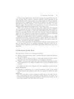
combustion process in the cylinder for given rotational speed depend on the ignition angle
advance before TDC (Figure 4).
Figure 4. Influence of ignition angle advance on the engine torque
The beginning of the mixture combustion follows after several crank angle rotation. While
this period certain chemical reactions follow in the mixture to form the radicals, which can
induce the combustion process. The energy in the spark provided a local rise in temperature
of several thousand degrees Kelvin, which cause any fuel vapour present to be raised above
its auto-ignition temperature. The auto-ignition temperature determines the possibility of
the break of the hydrocarbon chains and the charge has sufficient internal energy to oxidize
the carbon into CO
2 and water in the vapour state. Immediately, after the beginning of
combustion (ignition point) the initial flame front close to the spark plug moves in a radial
direction into the space of the combustion chamber and heats the unburned layers of air-fuel
mixture surrounding it.
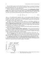
For the direct injection of CNG for small loads of the engine in stratified charge mode the
burning of the mixture depends on the pressure value at the end of compression stroke and
on the relative air-fuel ratio. These dependencies of the CNG burning for different mixture
composition and compression ratio are presented in Figure 5 [15]. The burning of CNG
mixture can occur in very small range of the compression pressure and lean mixture
composition and maximum combustion pressure reaches near 200 bars. For very lean
mixtures and higher compression ratios the misfire occurs, on the other hand for rich
Internal Combustion Engines
10
mixtures and high compression ratios the detonation is observed. During the cold start-up
the ignition process of the CNG mixture is much easier than with gasoline mixture because
of whole fuel is in the gaseous state. Today in the new ignition systems with electronic or
capacitor discharge the secondary voltage can reach value 40 kV in some microseconds.
Figure 5. The range of combustion limits for lean CNG mixture [3]
The higher voltage in the secondary circuit of the transformer and the faster spark rise
enable that the sparking has occurred even when the spark plug is covered by liquid
gasoline. With fuelling of the engine by CNG the sparking process should occur in every
condition of the engine loads and speeds. However, at higher compression ratio and higher
engine charging the final charge pressure increases dramatically in the moment of ignition
and this phenomenon influences on the sparking process.
5. Electric and thermal parameters of ignition
On the observation and test done before on the conventional ignition systems, the higher
pressure of the charge in the cylinder requires also higher sparking energy or less the gap of
the electrodes in the spark plug. The chemical delay of the mixture burning is a function of
the pressure, temperature and properties of the mixture and was performed by Spadaccini
[12] in the form:
92
2.43 10 exp[41560 / ( )]
z
pRT
(3)
where: p - pressure [bar], T - temperature [K] and R - gas constant [(bar cm
3
)/(mol K)].
The simplest definition of this delay was given by Arrhenius on the basis of a semi-
empirical dependence:
Factors Determing Ignition and Efficient Combustion in Modern Engines Operating on Gaseous Fuels
11
31.19
4650
0.44 10 exp
z
p
T
(4)
where p is the charge pressure at the end of the compression process [daN/cm
2
].
Experimental and theoretical studies divide the spark ignition into three phases:
breakdown, arc and glow discharge. They all have particular electrical properties. The
plasma of temperature above 6000 K and diameter equal the diameter of the electrodes
causes a shock pressure wave during several microseconds. At an early stage a cylindrical
channel of ionization about 40 m in diameter develops, together with a pressure jump and
a rapid temperature rise. Maly and Vogel [10] showed that an increase in breakdown energy
does not manifest itself a higher kernel temperatures, instead the channel diameter causing
a larger activated-gas volume. Since the ratio between the initial temperature of the mixture
and the temperature of the spark channel is much smaller than unity, the diameter d of the
cylindrical channel is given approximately by the following expression:
1
2
21
bd
E
d
hp
(5)
where
is ratio of the specific heats, h is the spark plug gap and p pressure. Ebd represents
the breakdown energy to produce the plasma kernel. Ballal and Lefebvre [6] considered the
following expression for the breakdown voltage Ubd and total spark energy Et:
5
2,8 10
5,5 ln( )
bd
ph
U
pd
0
i
t
t
EVIdt
(6)
One assumed, that the charge is isentropic conductive and the field attains a quasi-steady
state (no time influence). Knowing the potential of the electromagnetic field
and electrical
conductivity
the following equation can be used [12]:
div( grad ) 0
(7)
After a forming of the plasma between the electrodes the heat source
e
q
in the mixture can
be calculated directly from the electrical current in the secondary coil circuit I, which
changes during with time:
2
2
0
2(,)
e
R
I
q
rrzdr
(8)
where r and z are the coordinates of the ionization volume.
At leaner homogenous mixture the discharging of the energy by spark plug leads sometimes
to the misfire and increasing of the hydrocarbons emission. At stratified charge for the same
Internal Combustion Engines
12
total air-fuel ratio the sparking of the mixture can be improved by turning the injected fuel
directly near spark plug at strictly defined crank angle rotation depending on the engine
speed. The energy involved from the spark plug is delivered to the small volume near spark
plug. The total energy, which is induced by the spark plug is a function of the voltage and
current values in the secondary circuit of the ignition coil and time of the discharge. On the
other hand, values of voltage U and current I change in the discharge time and total energy
induced by the coil can be expressed as a integral of voltage U, current I and time t:
0
ign
EUIdt
(9)
where
is the time of current discharge by the secondary circuit of the ignition coil.
Integration of the measurement values of voltage and current in the secondary circuit of the
coil gives the total electric energy to the mixture charge near spark plug. The total internal
energy of the mixture near the spark plug increases in the period t = 0
and according to
the energy balance in the small volume the temperature of the charge in this region
continuously increases.
The modern conventional ignition system can give the burning energy
eburn = 60 mJ at the
secondary voltage 30 kV and burning current
iburn = 70 mA during 1.8 ms. In practice a
required value of the secondary voltage of the ignition system is calculated from the
following formula:
0.718
2
4700Ua
(10)
where:
U2 - secondary voltage [V],
a - gap between electrodes of the spark plug,
- compression ratio.
Figure 6. The secondary voltage as a function of compression pressure and electrode’s gap
Factors Determing Ignition and Efficient Combustion in Modern Engines Operating on Gaseous Fuels
13
For lower gaps and compression ratios the secondary voltage can be decreased. The
required secondary voltage as a function of compression pressure is presented in Figure 6
for different gaps of spark plug electrodes from 0.3 to 0.9 mm.
If one assumes that the electrical energy
E is delivered during period to a certain small
volume
V near spark plug with the temperature of the charge T1 and pressure p1 and
concentration of CNG fuel adequate to the air excess coefficient
, it is possible to calculate
the change of the charge temperature in this space. On the basis of the law of gas state and
balance of energy the specific internal energy
u of the charge in the next step of calculation is
defined.
1ii
uu dE
(11)
where
i is the step of calculations and dE is the energy delivered from the spark plug in step
time
d
. The internal energy is function of the charge mass m and temperature T, where
mass
m in volume V is calculated from the following dependency:
1
1
pV
m
RT
(12)
and gas constant
R is calculated on the mass concentration g of the n species in the mixture.
Mass of the charge consists of the fuel mass mf and air mass ma, which means:
af
mm m
(13)
For the mixture that contains only air and fuel (in our case CNG), the equivalent gas
constant is calculated as follows:
1
n
ii aa f f
RgRgRgR
(14)
In simple calculations the local relative air-fuel ratio
is obtained from the local
concentration of air and fuel:
a
f
m
Km
(15)
where
K is stoichiometric coefficient for a given fuel. For the CNG applied during the
experiments K=16.04 [kg air/kg CNG]. At assumption of the relative air-fuel ratio the
masses of fuel
mf and air ma can be obtained from the following formulas:
1
f
m
m
K
1
a
K
mm
K
(16)
After substitution of the fuel and air masses to the equation (10) the equivalence gas
constant R is defined only if the is known.
Internal Combustion Engines
14
1
1
af
RKRR
K
(17)
For whole volume
V the internal energy at the beginning of the ignition is defined as:
11
11 1
1
vvv
pV pV
U mcT cT c
RT R
(18)
The charge pressure during compression process increases as function of the crank angle
rotation from
p1 to p. When one knows the engine’s stroke S and diameter D of the cylinder
and compression ratio
it is possible to determine the change of pressure from start point to
another point. If the heat transfer will be neglected the pressure change in the cylinder can
be obtained from a simple formula as a function of time
t and engine speed n (rev/min):
30 1
1
c
c
dV
dp
kk
dt n V k dt
(19)
where
Vc is volume of the cylinder at crank angle and k is specific heat ratio (cp/cv).
For simplicity of calculations it was assumed that during compression stroke the specific
heat ratio for small period is constant (
k 1.36) and cylinder volume changes with
kinematics of crank mechanism. Delivery of electrical energy to the local volume results on
the increase of local internal energy and changing of temperature
T, which can be
determined from the following energy equation:
1vi vi
mc T mc T de
or
v
dT de
mc
dt dt
(20)
The electrical energy can be performed in a different way: with constant value during time
(rectangular form or according to the reality in a triangular form as shown in Figure 7.
Figure 7. Variation of electrical power from spark plug
Factors Determing Ignition and Efficient Combustion in Modern Engines Operating on Gaseous Fuels
15
If the total electrical energy amounts E and duration of sparking lasts (1.8 ms) then for the
first case the local power is
E/ for whole period of the sparking. For the second case
electrical power from the spark plug changes and for the first period can be expressed as:
max
2
I
tE
N
t
(21)
For the second period the electrical power can be determined as follows:
max
1
2
1
II
t
E
N
t
(22)
The temperature of the charge near the spark plug during the period
is computed as
follows:
1
()
v
dT N t dt
mc
(23)
For the first case (rectangular form) of variation of electrical power the change of the charge
temperature is computed from the following dependency:
1
v
E
dT dt
mc
(24)
For the second case (triangular form of power) the temperature of the local charge is
calculated as follows:
a.
1
st
period
max
12
v
tE
dT dt
mc t
(25)
b.
2
nd
period
max
1
12
1
v
t
E
dT dt
t
mc
(26)
At assuming of specific volumetric heat
cv as constant in a small period
the temperature of
the local charge is simply obtained by integration of given above equations as function of
time
t (t = 0 )
1
1.
v
Et
TT
mc
(27)
Internal Combustion Engines
16
2
1
max
2.
v
Et
aTT
mc t
(28)
max
12
2. 1
2
1
v
Et t
bTC
t
mc
(29)
The constant
C is calculated for the initial conditions for t/
= tmax/
with the end temperature
for 1
st
period as an initial temperature for 2
nd
period. The three cases are performed in a non-
dimensional time t/
. Because compression stroke in 4-stroke engine begins usually a=45
CA ABDC and thus the cylinder volume [3] can be calculated at
i
crank angle as follows:
1 cos(180 ) cos2(180 )
12 4 4
ss
aii
VV
V
(30)
The simple calculations of the increment of the local temperature in the region of the spark
plug were done at certain assumptions given below: swept volume of the cylinder - 450 cm
3
,
compression ratio – 12, crank constant
- 0.25, diameter of sparking region - 1 mm, height of
sparking region - 1 mm, closing of inlet valve - 45
CA ABDC, start angle of ignition - 20
CA BTDC.
For calculation the air-gas mixture was treated as an ideal gas (methane CH
4 and air at
=1.4). Two ignition systems were considered with ignition energy 40 and 60 mJ at
assumption of:
1.
constant sparking power (rectangular form) in period =2 ms
2.
variable sparking power (triangular form) in period =2 ms.
The results of calculations are performed in Figure 8 for those two ignition systems,
respectively. It was assumed that compression process begins after closing of the inlet valve
with constant coefficient of compression politrope
k=1.36.
Figure 8. Increment of the local temperature in the region of the spark plug for two ignition systems: a)
with constant sparking power, b) with variable sparking power (triangular form)
(a) (b)