MBA/SMA 0204, MBB/SMA 0207, MBE/SMA 0414 - Professional Thin Film Leaded Resistors docx
Bạn đang xem bản rút gọn của tài liệu. Xem và tải ngay bản đầy đủ của tài liệu tại đây (182.46 KB, 13 trang )
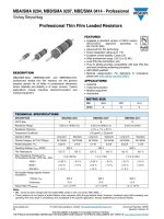
Professional Thin Film Leaded Resistors
MBA/SMA 0204, MBB/SMA 0207, MBE/SMA 0414 - Professional
Vishay Beyschlag
www.vishay.com For technical questions, contact: Document Number: 28766
22 Revision: 03-Dec-12
THIS DOCUMENT IS SUBJECT TO CHANGE WITHOUT NOTICE.
THE PRODUCTS DESCRIBED HEREIN AND THIS DOCUMENT\rARE SUBJECT TO SPECIFIC DISCLAIMERS, SET FORTH AT www.vishay.com/doc?91000
DESCRIPTION
MBA/SMA 0204, MBB/SMA 0207 and MBE/SMA 0414
professional leaded thin film resistors are the general
purpose resistor for all fields of professional electronics
where reliability and stability is of major concern. Typical
applications include industrial, telecommunication and
medical equipment.
FEATURES
Available in standard version or CECC version
(IECQ-CECC approved according to
EN 140101-806)
Advanced thin film technology
Power dissipation rating up to 1 W
Excellent overall stability: Class 0.25
Wide professional range: 0.22 to 22 M
Lead (Pb)-free termination wire
Pure tin plating provides compatibility with lead (Pb)-free
and lead containing soldering processes
AEC-Q200 qualified
Material categorization: For definitions of compliance
please see www.vishay.com/doc?99912
APPLICATIONS
Industrial
Telecommunication
Medical equipment
Automotive
Notes
• MB_ series has been merged with the related SMA series to form one series “MB_/SMA__”
• These resistors do not feature a limited lifetime when operated within the permissible limits. However, resistance value drift increasing over
operating time may result in exceeding a limit acceptable to the specific application, thereby establishing a functional lifetime.
METRIC SIZE
DIN 0204 0207 0414
CECC ABD
TECHNICAL SPECIFICATIONS
DESCRIPTION MBA/SMA 0204 MBB/SMA 0207 MBE/SMA 0414
CECC Size A B D
Resistance Range 0.22 to 10 M; 0 0.22 to 22 M; 0 0.22 to 22 M
Resistance Tolerance ± 5 %; ± 1 %; ± 0.5 %
Temperature Coefficient ± 50 ppm/K; ± 25 ppm/K
Operation Mode Long term Standard Long term Standard Long term Standard
Climatic Category (LCT/UCT/Days) 55/125/56 55/155/56 55/125/56 55/155/56 55/125/56 55/155/56
Rated Dissipation, P
70
0.25 W 0.4 W 0.4 W 0.6 W 0.65 W 1.0 W
Operating Voltage, U
max.
AC/DC 200 V 350 V 500 V
Film Temperature 125 C 155 C 125 C155C 125 C155C
Max. Resistance Change at P
70
for Resistance Range, R/R max., After:
1 to 332 k 1 to 1 M 1 to 2.4 M
1000 h 0.25 % 0.5 % 0.25 % 0.5 % 0.2 % 0.4 %
8000 h 0.5 % 1.0 % 0.5 % 1.0 % 0.4 % 0.8 %
225 000 h 1.5 % - 1.5 % - 1.2 % -
Permissible Voltage Against Ambient
(Insulation):
1 Minute; U
ins
300 V 500 V 800 V
Continuous 75 V 75 V 75 V
Failure Rate: FIT
observed
0.1 x 10
-9
/h 0.1 x 10
-9
/h 0.1 x 10
-9
/h
Document Number: 28766 For technical questions, contact:
www.vishay.com
Revision: 03-Dec-12 23
MBA/SMA 0204, MBB/SMA 0207, MBE/SMA 0414 - Professional
Professional Thin Film Leaded Resistors
Vishay Beyschlag
THIS DOCUMENT IS SUBJECT TO CHANGE WITHOUT NOTICE.
THE PRODUCTS DESCRIBED HEREIN AND THIS DOCUMENT\rARE SUBJECT TO SPECIFIC DISCLAIMERS, SET FORTH AT www.vishay.com/doc?91000
Notes
(1)
Standard products are not CECC approved
(2)
Resistance value to be selected from E24 series for ± 5 %, ± 2 % tolerance, from E24/E96 series for ± 1 % tolerance and from E24/E192 for
± 0.5 % tolerance
(3)
AEC-Q200 qualification applies to products with TCR = ± 50 ppm/K and tolerance = ± 1 % in the ranges of 10 to 301 k for MBA/SMA 0204,
10 to 7.5 M for MBB/SMA 0207, and 10 to 22 M for MBE/SMA 0414
• Resistance ranges printed in bold are preferred TCR/tolerance combinations with optimized availability
• The PART NUMBER shown above is to facilitate the unified part numbering system for ordering products
PART NUMBER AND PRODUCT DESCRIPTION - STANDARD PRODUCTS
(1)
PART NUMBER: MBB02070C1001FCT00
TYPE/SIZE VARIANT TCR RESISTANCE TOLERANCE PACKAGING SPECIAL
MBA0204
=
MBA/SMA 0204
MBB0207
=
MBB/SMA 0207
MBE0414
=
MBE/SMA 0414
0 = Neutral
N = RB Radial 5 mm
for MBB/SMA0207
S = UB Radial 2.5 mm
for MBB/SMA0207
I = L0 Welding joint not
lacquered for
MBB/SMA 0207
B = KL Lacquered
welding joint for
MBA/SMA 0204
D = ± 25 ppm/K
C = ± 50 ppm/K
Z = Jumper
3 digit value
1 digit multiplier
MULTIPLIER
7 = *10
-3
2 = *10
2
8 = *10
-2
3 = *10
3
9 = *10
-1
4 = *10
4
0 = *10
0
5 = *10
5
1 = *10
1
6 = *10
6
0000 = Jumper
D = ± 0.5 %
F = ± 1 %
J = ± 5 %
Z = Jumper
CT
C1
RP
R2
R4
N4
00 = Standard
PRODUCT DESCRIPTION: MBB/SMA 0207-50 1 % CT 1K0
MBB/SMA 0207 - 50 1 % CT 1K0
TYPE/SIZE TCR TOLERANCE
VARIANT
PACKAGING RESISTANCE
MBA/SMA 0204
MBB/SMA 0207
MBE/SMA 0414
± 25 ppm/K
± 50 ppm/K
± 0.5 %
± 1.0 %
± 5.0 %
RB
UB
L0
KL
CT
C1
RP
R2
R4
N4
1K0 = 1 k
51R1 = 51.1
TEMPERATURE COEFFICIENT AND RESISTANCE RANGE - STANDARD PRODUCTS
(1)
TCR TOLERANCE
RESISTANCE RANGE
(2)(3)
MBA/SMA 0204 MBB/SMA 0207 MBE/SMA 0414
± 50 ppm/K
± 5 % 0.22 to 0.91
0.22 to 0.91
11 M to 22 M
0.22 to 0.91
± 2% - 0.22 to 0.91 -
± 1 % 1 to 10 M 1 to 10 M 1 to 22 M
± 0.5 % 10 to 475 k 10 to 1 M 10 to 2.4 M
± 25 ppm/K
± 1 % 10 to 475 k 10 to 1 M 10 to 2.4 M
± 0.5 % 10 to 475 k 10 to 1 M 10 to 2.4 M
Jumper - 10 m; I
max.
= 3.0 A 10 m, I
max.
= 5.0 A -
B2 0C10FCT0BM 701000
www.vishay.com For technical questions, contact: Document Number: 28766
24 Revision: 03-Dec-12
MBA/SMA 0204, MBB/SMA 0207, MBE/SMA 0414 - Professional
Vishay Beyschlag
Professional Thin Film Leaded Resistors
THIS DOCUMENT IS SUBJECT TO CHANGE WITHOUT NOTICE.
THE PRODUCTS DESCRIBED HEREIN AND THIS DOCUMENT\rARE SUBJECT TO SPECIFIC DISCLAIMERS, SET FORTH AT www.vishay.com/doc?91000
Notes
(1)
Approval is according to EN 140101-806, version A
(2)
Resistance value to be selected from E24 series for ± 5 %, ± 2 % tolerance, from E24/E96 series for ± 1 % tolerance and from E24/E192 for
± 0.5 % tolerance
(3)
AEC-Q200 qualification applies to products with TCR = ± 50 ppm/K and tolerance = ± 1 % in the ranges of 10 to 301 k for MBA/SMA 0204,
10 Ohm to 7.5 M for MBB/SMA 0207, and 10 to 22 M for MBE/SMA 0414
• Resistance ranges printed in bold are preferred TCR/tolerance combinations with optimized availability
• The PART NUMBER shown above is to facilitate the unified part numbering system for ordering products
• Radial version (RB, UB) cannot be qualified according to CECC so these can only be ordered as standard products
PART NUMBER AND PRODUCT DESCRIPTION - CECC APPROVED PRODUCTS
(1)
PART NUMBER: MBB0207VC1001FCT00
TYPE/SIZE VARIANT TCR RESISTANCE TOLERANCE PACKAGING SPECIAL
MBA0204
=
MBA/SMA 0204
MBB0207
=
MBB/SMA 0207
MBE0414
=
MBE/SMA 0414
V = CECC 06 D = ± 25 ppm/K
C = ± 50 ppm/K
Z = Jumper
3 digit value
1 digit multiplier
MULTIPLIER
7 = *10
-3
2 = *10
2
8 = *10
-2
3 = *10
3
9 = *10
-1
4 = *10
4
0 = *10
0
5 = *10
5
1 = *10
1
6 = *10
6
0000 = Jumper
D = ± 0.5 %
F = ± 1 %
J = ± 5 %
Z = Jumper
CT
C1
RP
R2
00 = Standard
L0 = Welding joint
not lacquered for
MBB/SMA 0207
KL = Lacquered
welding joint for
MBA/SMA 0204
PRODUCT DESCRIPTION: MBB/SMA 0207-50 1 % CECC 06 CT 1K0
MBB/SMA 0207 - 50 1 % CECC 06 CT 1K0
TYPE/SIZE TCR TOLERANCE
VARIANT
PACKAGING RESISTANCE
MBA/SMA 0204
MBB/SMA 0207
MBE/SMA 0414
± 25 ppm/K
± 50 ppm/K
± 0.5 %
± 1.0 %
± 5.0 %
CECC 06
CECC 06 L0
CECC 06 KL
CT
C1
RP
R2
1K0 = 1 k
51R1 = 51.1
TEMPERATURE COEFFICIENT AND RESISTANCE RANGE - CECC APPROVED PRODUCTS
(1)
TCR TOLERANCE
RESISTANCE RANGE
(2)(3)
MBA/SMA 0204 MBB/SMA 0207 MBE/SMA 0414
± 50 ppm/K
± 5 % 0.22 to 0.91
0.22 to 0.91
11 M to 22 M
0.22 to 0.91
± 1 % 1 to 10 M 1 to 10 M 1 to 22 M
± 0.5 % 10 to 332 k 10 to 1 M 10 to 2.43 M
± 25 ppm/K
± 1 % 10 to 475 k 10 to 1 M 10 to 2.43 M
± 0.5 % 10 to 475 k 10 to 1 M 10 to 2.43 M
Jumper - 10 m; I
max.
= 3.0 A 10 m, I
max.
= 5.0 A -
B2 VC10FCT0BM 701000
Document Number: 28766 For technical questions, contact:
www.vishay.com
Revision: 03-Dec-12 25
MBA/SMA 0204, MBB/SMA 0207, MBE/SMA 0414 - Professional
Professional Thin Film Leaded Resistors
Vishay Beyschlag
THIS DOCUMENT IS SUBJECT TO CHANGE WITHOUT NOTICE.
THE PRODUCTS DESCRIBED HEREIN AND THIS DOCUMENT\rARE SUBJECT TO SPECIFIC DISCLAIMERS, SET FORTH AT www.vishay.com/doc?91000
Note
• For details related to packaging specs, refer datasheet link www.vishay.com/doc?28721
DIMENSIONS
Note
(1)
For 7.5 M < 10.0 mm, use version MBB/SMA 0207 L0 (welding joint not lacquered)
PACKAGING - Axial products
TYPE
REEL
TAPING ACC. IEC 60286-1
BOX
TAPING ACC. IEC 60286-1
PIECES CODE PIECES CODE
MBA/SMA 0204 5000 RP
1000
5000
C1
CT
MBB/SMA 0207 5000 RP
1000
5000
C1
CT
MBE/SMA 0414 2500 R2 1000 C1
DIMENSIONS - Leaded resistor types, mass and relevant physical dimensions
TYPE
D
max.
(mm)
L
max.
(mm)
d
nom.
(mm)
I
min.
(mm)
M
min.
(mm)
MASS
(mg)
MBA/SMA 0204 1.6 3.6 0.5 29.0 5.0 125
MBB/SMA 0207 2.5 6.5 0.6 28.0 10.0
(1)
220
MBE/SMA 0414 4.2 11.9 0.8 31.0 15.0 700
L
d
D
I
I
M
www.vishay.com For technical questions, contact: Document Number: 28766
26 Revision: 03-Dec-12
MBA/SMA 0204, MBB/SMA 0207, MBE/SMA 0414 - Professional
Vishay Beyschlag
Professional Thin Film Leaded Resistors
THIS DOCUMENT IS SUBJECT TO CHANGE WITHOUT NOTICE.
THE PRODUCTS DESCRIBED HEREIN AND THIS DOCUMENT\rARE SUBJECT TO SPECIFIC DISCLAIMERS, SET FORTH AT www.vishay.com/doc?91000
MBB/SMA 0207 WITH RADIAL TAPING
LEAD SPACING (UB = 2.5 mm), SIZE 0207
LEAD SPACING (RB = 5.0 mm), SIZE 0207
PACKAGING - Radial products
TYPE
REEL
TAPING ACC. IEC 60286-2
BOX
TAPING ACC. IEC 60286-2
PIECES CODE PIECES CODE
MBB/SMA 0207 RB
4000 R4 4000 N4
MBB/SMA 0207 UB
L
H
C
H
1
F
P
3 max.
Insulated
W
Direction of unreeling
DIMENSIONS in millimeters
Pitch of components P 12.7 ± 1.0
Lead spacing F 2.5 + 0.6, - 0.1
Width of carrier tape W 18.0 + 1.0, - 0.5
Body to hole center H 18.0 ± 2.0
Height for cutting (max.) L 11
Height for bending C 2.5 + 0, - 0.5
Height for insertion (max.) H
1
32
H
1
L
H
C
P
F
H
0
W
Insulated
3 max.
Direction of unreeling
DIMENSIONS in millimeters
Pitch of components P 12.7 ± 1.0
Lead spacing F 5.0 + 0.6, - 0.1
Width of carrier tape W 18.0 + 1.0, - 0.5
Body to hole center H 18.0 ± 2.0
Lead crimp to hole
center
H
0
16.0 ± 0.5
Height for cutting (max.) L 11
Height for bending C 2.5 + 0, - 0.5
Height for insertion (max.) H
1
32
Document Number: 28766 For technical questions, contact:
www.vishay.com
Revision: 03-Dec-12 27
MBA/SMA 0204, MBB/SMA 0207, MBE/SMA 0414 - Professional
Professional Thin Film Leaded Resistors
Vishay Beyschlag
THIS DOCUMENT IS SUBJECT TO CHANGE WITHOUT NOTICE.
THE PRODUCTS DESCRIBED HEREIN AND THIS DOCUMENT\rARE SUBJECT TO SPECIFIC DISCLAIMERS, SET FORTH AT www.vishay.com/doc?91000
DESCRIPTION
Production is strictly controlled and follows an extensive
set of instructions established for reproducibility. A
homogeneous film of metal alloy is deposited on a high grade
ceramic body and conditioned to achieve the desired
temperature coefficient. Plated steel termination caps are
firmly pressed on the metallized rods. A special laser is used
to achieve the target value by smoothly cutting a helical
groove in the resistive layer without damaging the ceramics.
Connecting wires of electrolytic copper plated with 100 %
pure tin are welded to the termination caps. The resistor
elements are covered by a light blue protective coating
designed for electrical, mechanical and climatic protection.
Four or five color code rings designate the resistance value
and tolerance in accordance with IEC 60062.
The result of the determined production is verified by an
extensive testing procedure performed on 100 % of the
individual resistors. Only accepted products are stuck
directly on the adhesive tapes in accordance with
IEC 60286-1 or for the radial versions in accordance to
IEC 60286-2.
ASSEMBLY
The resistors are suitable for processing on automatic
insertion equipment and cutting and bending machines.
Excellent solderability is proven, even after extended
storage. They are suitable for automatic soldering using
wave or dipping.
The resistors are completely lead (Pb)-free, the pure tin
plating provides compatibility with lead (Pb)-free and
lead-containing soldering processes. The immunity of the
plating against tin whisker growth has been proven under
extensive testing.
The encapsulation is resistant to all cleaning solvents
commonly used in the electronics industry, including
alcohols, esters and aqueous solutions. The suitability of
conformal coatings, if applied, shall be qualified by
appropriate means to ensure the long-term stability of the
whole system.
All products comply with GADSL
(1)
and the
CEFIC-EECA-EICTA
(2)
list of legal restrictions on
hazardous substances. This includes full compliance with
the following directives:
2000/53/EC End of Vehicle Life Directive (ELV) and
Annex II (ELVII)
2002/95/EC Restriction of the use of Hazardous
Substances Directive (RoHS)
2002/96/EC Waste Electrical and Electrical Equipment
Directive (WEEE)
APPROVALS
The resistors (CECC version) are approved within the
IECQ-CECC Quality Assessment System for Electronic
Components to the detail specification EN 140101-806
which refers to EN 60115-1 and EN 140100 and the variety
of environmental test procedures of the IEC 60068 series.
Conformity is attested by the use of the CECC logo ( ) as
the Mark of Conformity on the package label for the CECC
version.
Vishay BEYSCHLAG has achieved "Approval of
Manufacturer" in accordance with IEC QC 001002-3,
clause 2. The release certificate for "Technology Approval
Schedule" in accordance with CECC 240001 based on
IEC QC 001002-3, clause 6 is granted for the Vishay
BEYSCHLAG manufacturing process.
RELATED PRODUCTS
For a corelated range of precision TCR and tolerance
specifications see the datasheet:
“Precision Thin Film Leaded Resistors”, document no.
28767
For products approved to EN 140101-806, version E, with
established reliability and failure rate level E7 (Quality factor
Q
= 0.1), see the datasheet:
“Established Reliability Thin Film Leaded Resistors”,
document no. 28768
Notes
(1)
Global Automotive Declarable Substance List, see www.gadsl.org
(2)
CEFIC (European Chemical Industry Council), EECA (European Electronic Component Manufacturers Association), EICTA (European
trade organisation representing the information and communications technology and consumer electronics), see
www.eicta.org/index.php?id=1053&id_article=340
www.vishay.com For technical questions, contact: Document Number: 28766
28 Revision: 03-Dec-12
MBA/SMA 0204, MBB/SMA 0207, MBE/SMA 0414 - Professional
Vishay Beyschlag
Professional Thin Film Leaded Resistors
THIS DOCUMENT IS SUBJECT TO CHANGE WITHOUT NOTICE.
THE PRODUCTS DESCRIBED HEREIN AND THIS DOCUMENT\rARE SUBJECT TO SPECIFIC DISCLAIMERS, SET FORTH AT www.vishay.com/doc?91000
FUNCTIONAL PERFORMANCE
C
100 150
0
- 50 50
0.5
1
W
70
Ambient Temperature
amb
ϑ
Power Dissipation
P
MBE/SMA 0414
MBA/SMA 0204
MBB/SMA 0207
0
Derating - Standard Operation
C
100 150
0
- 50 50
0.5
1
W
70
Ambient Temperature
amb
ϑ
Power Dissipation
P
0
MBE/SMA 0414
MBA/SMA 0204
MBB/SMA 0207
Derating Long Term Operation
0
40
K
60
20
80
0 0.4 0.8 1 1.20.2 0.60.1 0.3 0.5 0.7 0.9 1.1 W
Load
P
Temperature Rise
T
r
MBE/SMA 0414
MBA/SMA 0204
MBB/SMA 0207
Rise of surface temperature
Temperature Rise
Document Number: 28766 For technical questions, contact:
www.vishay.com
Revision: 03-Dec-12 29
MBA/SMA 0204, MBB/SMA 0207, MBE/SMA 0414 - Professional
Professional Thin Film Leaded Resistors
Vishay Beyschlag
THIS DOCUMENT IS SUBJECT TO CHANGE WITHOUT NOTICE.
THE PRODUCTS DESCRIBED HEREIN AND THIS DOCUMENT\rARE SUBJECT TO SPECIFIC DISCLAIMERS, SET FORTH AT www.vishay.com/doc?91000
100 µs 1 ms 10 ms
1
1 s
10 s
0.1
W
10 µs 100 ms
10
100
Pulse Duration
t
i
Pulse Load
P
max.
MBE/SMA 0414
MBA/SMA 0204
MBB/SMA 0207
Maximum pulse load, single pulse; for permissible resistance change equivalent to 8000 h operation.
Single Pulse
100 µs 1 ms 10 ms
1
1 s
10 s
0.1
W
10 µs 100 ms
100
10
Pulse Duration
t
i
Continuous Pulse Load
P
max.
MBE/SMA 0414
MBA/SMA 0204
MBB/SMA 0207
Maximum pulse load, continuous pulses; for permissible resistance change equivalent to 8000 h operation.
Continuous Pulse
100 V
1 kV
100 µs 1 ms 10 ms
1 s
10 s10 µs 100 ms
Pulse Duration
t
i
Pulse Voltage
U
max.
MBE/SMA 0414
MBA/SMA 0204
MBB/SMA 0207
Maximum pulse voltage, single and continuous pulses; for permissible resistance change equivalent to 8000 h operation.
Pulse Voltage
www.vishay.com For technical questions, contact: Document Number: 28766
30 Revision: 03-Dec-12
MBA/SMA 0204, MBB/SMA 0207, MBE/SMA 0414 - Professional
Vishay Beyschlag
Professional Thin Film Leaded Resistors
THIS DOCUMENT IS SUBJECT TO CHANGE WITHOUT NOTICE.
THE PRODUCTS DESCRIBED HEREIN AND THIS DOCUMENT\rARE SUBJECT TO SPECIFIC DISCLAIMERS, SET FORTH AT www.vishay.com/doc?91000
100 V
1 kV
10 V
10 kV
100 Ω 1 kΩ 100 kΩ 1 MΩ
10 Ω
10 MΩ
Resistance Value
R
Test Voltage
10 kΩ
MBE/SMA 0414
MBA/SMA 0204
MBB/SMA 0207
Pulse load rating in accordance with IEC 60115-1, 4.27; 1.2 µs/50 µs; 5 pulses at 12 s intervals;
for permissible resistance change 0.5 %.
1.2/50 Pulse
100 V
1 kV
10 V
10 kV
100 Ω 1 kΩ 100 kΩ 1 MΩ
10 Ω
10 MΩ
Resistance Value
R
Test Voltage
10 kΩ
MBE/SMA 0414
MBA/SMA 0204
MBB/SMA 0207
Pulse load rating in accordance with IEC 60115-1, 4.27; 10 µs/700 µs; 10 pulses at 1 minute intervals;
for permissible resistance change 0.5 %.
10/700 Pulse
0.01
0.1
1
100
Ω
µV/V
MBE/SMA 0414
MBA/SMA 0204
MBB/SMA 0207
1K 10K 100K 1M 10M
Resistance Value
R
Current Noise
A
1
Current noise - A
1
in accordance with IEC 60195
Document Number: 28766 For technical questions, contact:
www.vishay.com
Revision: 03-Dec-12 31
MBA/SMA 0204, MBB/SMA 0207, MBE/SMA 0414 - Professional
Professional Thin Film Leaded Resistors
Vishay Beyschlag
THIS DOCUMENT IS SUBJECT TO CHANGE WITHOUT NOTICE.
THE PRODUCTS DESCRIBED HEREIN AND THIS DOCUMENT\rARE SUBJECT TO SPECIFIC DISCLAIMERS, SET FORTH AT www.vishay.com/doc?91000
TESTS AND REQUIREMENTS
Essentially all tests are carried out in accordance with the
following specifications:
EN 60115-1, generic specification (includes tests)
EN 140100, sectional specification (includes schedule for
qualification approval)
EN 140101-806 (successor of CECC 40101-806), detail
specification (includes schedule for conformance inspection)
The Test and Requirements table contains only the most
important tests. For the full test schedule refer to the
documents listed above. The testing also covers most of the
requirements specified by EIA/IS-703 and JIS-C-5202.
The tests are carried out in accordance with IEC 60068-2-xx
test method and under standard atmospheric conditions in
accordance with IEC 60068-1, 5.3. Climatic category
LCT/UCT/56 (rated temperature range: Lower category
temperature, upper category temperature; damp heat,
steady state, test duration: 56 days) is valid.
Unless otherwise specified the following values apply:
Temperature: 15 °C to 35 °C
Relative humidity: 45 % to 75 %
Air pressure: 86 kPa to 106 kPa (860 mbar to 1060 mbar).
For performing some of the tests, the components are
mounted on a test board in accordance with IEC 60115-1,
4.31.
In Test Procedures and Requirements table, only the tests
and requirements are listed with reference to the relevant
clauses of IEC 60115-1 and IEC 60068-2-xx test methods. A
short description of the test procedure is also given.
TEST PROCEDURES AND REQUIREMENTS
IEC
60115-1
CLAUSE
IEC
60068-2-
TEST
METHOD
TEST PROCEDURE
REQUIREMENTS
PERMISSIBLE CHANGE (R max.)
Stability for product
types:
STABILITY
CLASS 0.5
STABILITY
CLASS 1
STABILITY
CLASS 2
MBA/SMA 0204 1 to 332 k 0.22 to < 1 > 332 k
MBB/SMA 0207 1 to 1 M 0.22 to < 1 > 1 M
MBE/SMA 0414 1 to 2.4 M 0.22 to < 1 > 2.4 M
4.5 - Resistance ± 5 % R; ± 1 % R; ± 0.5 % R
4.8 -
Temperature
coefficient
At (20/LCT/20) °C and
(20/UCT/20) °C
± 50 ppm/K; ± 25 ppm/K
4.25.1
-
Endurance
at 70 C:
Standard
operation mode
U = or
U = U
max.
;
1.5 h ON; 0.5 h OFF
70 °C; 1000 h ± (0.5 % R + 0.05)
(1)
± 0.5 % R
70 °C; 8000 h ± (1 % R +0.05)
(2)
± 1 % R
-
Endurance
at 70 C:
Long term
operation mode
U = or
U = U
max.
;
1.5 h ON; 0.5 h OFF
70 °C; 1000 h ± (0.25 % R +0.05)
(3)
± 0.25 % R
70 °C; 8000 h ± (0.5 % R +0.05)
(4)
± 0.5 % R
4.25.3
Endurance at
upper category
temperature
125 °C; 1000 h ± (0.25 % R + 0.05 ) ± (0.5 % R + 0.05 )± 1 %R
155 °C; 1000 h ± (0.5 % R + 0.05 )± (1 %R + 0.05 )± 2 %R
4.24 78 (Cab)
Damp heat,
steady state
(40 ± 2) °C; 56 days;
(93 ± 3) % RH
± (0.5 % R + 0.05 )± (1 %R + 0.05 )± 2 %R
P
70
x R
P
70
x R
www.vishay.com For technical questions, contact: Document Number: 28766
32 Revision: 03-Dec-12
MBA/SMA 0204, MBB/SMA 0207, MBE/SMA 0414 - Professional
Vishay Beyschlag
Professional Thin Film Leaded Resistors
THIS DOCUMENT IS SUBJECT TO CHANGE WITHOUT NOTICE.
THE PRODUCTS DESCRIBED HEREIN AND THIS DOCUMENT\rARE SUBJECT TO SPECIFIC DISCLAIMERS, SET FORTH AT www.vishay.com/doc?91000
Note
(1)
± (0.4 % R + 0.05 ) for MBE/SMA 0414
(2)
± (0.8 % R + 0.05 ) for MBE/SMA 0414
(3)
± (0.2 % R + 0.05 ) for MBE/SMA 0414
(4)
± (0.4 % R + 0.05 ) for MBE/SMA 0414
4.23
Climatic
sequence:
4.23.2 2 (Ba) Dry heat 155 °C; 16 h
4.23.3 30 (Db)
Damp heat,
cyclic
55 °C; 24 h;
90 % to 100 % RH;
1 cycle
4.23.4 1 (Aa) Cold - 55 °C; 2 h
4.23.5 13 (M)
Low air
pressure
8.5kPa; 2h;
15 °C to 35 °C
4.23.6 30 (Db)
Damp heat,
cyclic
55 °C; 5 days;
95 % to 100 % RH;
5 cycles
± (0.5 % R + 0.05 )
no visible
damage
± (1 % R + 0.05 )
no visible
damage
± 2 % R
no visible
damage
4.13 -
Short time
overload
Room temperature;
U = 2.5 x or
U = 2 x U
max.
; 5 s
± (0.1 % R + 0.01)
no visible
damage
± (0.25 % R + 0.05 )
no visible
damage
± 0.5 % R
no visible
damage
4.19 14 (Na)
Rapid change
of temperature
30 min at LCT = - 55 °C
30 min at UCT= 155 °C
5 cycles ± (0.1 % R + 0.01 ) ± (0.25 % R + 0.05 ) ± 0.5 % R
MBA/SMA 0204:
500 cycles
MBB/SMA 0207:
200 cycles
MBE/SMA 0414:
100 cycles
± (0.5 % R + 0.05 ) ± (0.5 % R + 0.05 ) ± (0.5 % R + 0.05 )
4.29 45 (XA)
Component
solvent
resistance
Isopropyl alcohol
+ 23 °C; toothbrush
method
Marking legible;
no visible damage
4.18.2 20 (Tb)
Resistance to
soldering heat
Unmounted
components;
(260 ± 3) °C;
(10 ± 1) s
± (0.1 % R + 0.01 )
no visible
damage
± (0.25 % R + 0.05 )
no visible
damage
± 0.5 % R
no visible
damage
4.17 20 (Ta) Solderability
+ 235 °C; 2 s
solder bath method;
SnPb40
Good tinning (> 95 % covered, no visible damage)
+ 245 °C; 3 s
solder bath method;
SnAg3Cu0.5
4.22 6 (B4) Vibration
6 h; 10 Hz to 2000 Hz
1.5 mm or 196 m/s
2
± (0.1 % R + 0.01 ) ± (0.25 % R + 0.05 ) ± 0.5 % R
4.16
21 (Ua
1
)
21 (Ub)
21 (Uc)
Robustness of
terminations
Tensile, bending and
torsion
± (0.1 % R + 0.01 ) ± (0.25 % R + 0.05 ) ± 0.5 % R
4.7 - Voltage proof U
RMS
= U
ins
; 60 s No flashover or breakdown
4.40 -
Electrostatic
discharge
(human body
model)
IEC 61340-3-1;
3 pos. + 3 neg.
MBA/SMA 0204: 2 kV
MBB/SMA 0207: 4 kV
MBE/SMA 0414: 6 kV
± (0.5 % R +0.05 )
TEST PROCEDURES AND REQUIREMENTS
IEC
60115-1
CLAUSE
IEC
60068-2-
TEST
METHOD
TEST PROCEDURE
REQUIREMENTS
PERMISSIBLE CHANGE (R max.)
Stability for product
types:
STABILITY
CLASS 0.5
STABILITY
CLASS 1
STABILITY
CLASS 2
MBA/SMA 0204 1 to 332 k 0.22 to < 1 > 332 k
MBB/SMA 0207 1 to 1 M 0.22 to < 1 > 1 M
MBE/SMA 0414 1 to 2.4 M 0.22 to < 1 > 2.4 M
P
70
x R
Document Number: 28766 For technical questions, contact:
www.vishay.com
Revision: 03-Dec-12 33
MBA/SMA 0204, MBB/SMA 0207, MBE/SMA 0414 - Professional
Professional Thin Film Leaded Resistors
Vishay Beyschlag
THIS DOCUMENT IS SUBJECT TO CHANGE WITHOUT NOTICE.
THE PRODUCTS DESCRIBED HEREIN AND THIS DOCUMENT\rARE SUBJECT TO SPECIFIC DISCLAIMERS, SET FORTH AT www.vishay.com/doc?91000
HISTORICAL 12NC INFORMATION
The resistors had a 12-digit numeric code starting with
2312
The subsequent 4 digits indicated the resistor type,
specification and packaging; see the 12NC table
The remaining 4 digits indicated the resistance value:
- The first 3 digits indicated the resistance value
- The last digit indicated the resistance decade in
accordance with resistance decade table
Resistance Decade
Historical 12NC Example
The 12NC code of a MBA 0204 resistor, value 47.5 k and
TCR 50 with ± 1 % tolerance, supplied on bandolier in a box
of 5000 units was: 2312 905 14753.
RESISTANCE DECADE LAST DIGIT
0.1 to 0.999 7
1 to 9.99 8
10 to 99.9 9
100 to 999 1
1 k to 9.99 k 2
10 k to 99.9 k 3
100 k to 999 k 4
1M to 9.99 M 5
10 M to 99.9 M 6
HISTORICAL 12NC - Resistor type and packaging
DESCRIPTION
2312
AMMOPACK REEL
TYPE TCR TOL. C1 1000 units CT 5000 units R1 1000 units R2 2500 units RP 5000 units
MBA 0204
± 50 ppm/K
± 5 % 900 3 905 3 700 3 - 805 3
± 1 % 900 1 905 1 700 1 - 805 1
± 0.5 % 900 5 905 5 700 5 - 805 5
± 25 ppm/K
± 1 % 901 1 906 1 701 1 - 806 1
± 0.5 % 901 5 906 5 701 5 - 806 5
Jumper - 900 90001 905 90001 700 90001 - 805 90001
MBB 0207
± 50 ppm/K
± 5 % 910 3 915 3 710 3 - 815 3
± 1 % 910 1 915 1 710 1 - 815 1
± 0.5 % 910 5 915 5 710 5 - 815 5
± 25 ppm/K
± 1 % 911 1 916 1 711 1 - 816 1
± 0.5 % 911 5 916 5 711 5 - 816 5
Jumper - 910 90001 915 90001 710 90001 - 815 90001
MBE 0414
± 50 ppm/K
± 5 % 920 3 - - 825 3 -
± 1 % 920 1 - - 825 1 -
± 0.5 % 920 5 - - 825 5 -
± 25 ppm/K
± 1 % 921 1 - - 826 1 -
± 0.5 % 921 5 - - 826 5 -
Legal Disclaimer Notice
www.vishay.com
Vishay
Revision: 02-Oct-12
1
Document Number: 91000
Disclaimer
ALL PRODUCT, PRODUCT SPECIFICATIONS AND DATA ARE SUBJECT TO CHANGE WITHOUT NOTICE TO IMPROVE
RELIABILITY, FUNCTION OR DESIGN OR OTHERWISE.
Vishay Intertechnology, Inc., its affiliates, agents, and employees, and all persons acting on its or their behalf (collectively,
“Vishay”), disclaim any and all liability for any errors, inaccuracies or incompleteness contained in any datasheet or in any other
disclosure relating to any product.
Vishay makes no warranty, representation or guarantee regarding the suitability of the products for any particular purpose or
the continuing production of any product. To the maximum extent permitted by applicable law, Vishay disclaims (i) any and all
liability arising out of the application or use of any product, (ii) any and all liability, including without limitation special,
consequential or incidental damages, and (iii) any and all implied warranties, including warranties of fitness for particular
purpose, non-infringement and merchantability.
Statements regarding the suitability of products for certain types of applications are based on Vishay’s knowledge of typical
requirements that are often placed on Vishay products in generic applications. Such statements are not binding statements
about the suitability of products for a particular application. It is the customer’s responsibility to validate that a particular
product with the properties described in the product specification is suitable for use in a particular application. Parameters
provided in datasheets and/or specifications may vary in different applications and performance may vary over time. All
operating parameters, including typical parameters, must be validated for each customer application by the customer’s
technical experts. Product specifications do not expand or otherwise modify Vishay’s terms and conditions of purchase,
including but not limited to the warranty expressed therein.
Except as expressly indicated in writing, Vishay products are not designed for use in medical, life-saving, or life-sustaining
applications or for any other application in which the failure of the Vishay product could result in personal injury or death.
Customers using or selling Vishay products not expressly indicated for use in such applications do so at their own risk. Please
contact authorized Vishay personnel to obtain written terms and conditions regarding products designed for such applications.
No license, express or implied, by estoppel or otherwise, to any intellectual property rights is granted by this document or by
any conduct of Vishay. Product names and markings noted herein may be trademarks of their respective owners.
Material Category Policy
Vishay Intertechnology, Inc. hereby certifies that all its products that are identified as RoHS-Compliant fulfill the
definitions and restrictions defined under Directive 2011/65/EU of The European Parliament and of the Council
of June 8, 2011 on the restriction of the use of certain hazardous substances in electrical and electronic equipment
(EEE) - recast, unless otherwise specified as non-compliant.
Please note that some Vishay documentation may still make reference to RoHS Directive 2002/95/EC. We confirm that
all the products identified as being compliant to Directive 2002/95/EC conform to Directive 2011/65/EU.
Vishay Intertechnology, Inc. hereby certifies that all its products that are identified as Halogen-Free follow Halogen-Free
requirements as per JEDEC JS709A standards. Please note that some Vishay documentation may still make reference
to the IEC 61249-2-21 definition. We confirm that all the products identified as being compliant to IEC 61249-2-21
conform to JEDEC JS709A standards.