fluidization solids handling and processing industrial applications
Bạn đang xem bản rút gọn của tài liệu. Xem và tải ngay bản đầy đủ của tài liệu tại đây (17.48 MB, 906 trang )
JMR
24-Sep-01
FLUIDIZATION, SOLIDS
HANDLING, AND PROCESSING
Industrial Applications
np
NOYES PUBLICATIONS
Westwood, New Jersey, U.S.A.
Edited by
Wen-Ching Yang
Siemens Westinghouse Power Corporation
Pittsburgh, Pennsylvania
Copyright © 1998 by Noyes Publications
No part of this book may be reproduced or
utilized in any form or by any means, elec-
tronic or mechanical, including photocopying,
recording or by any information storage and
retrieval system, without permission in writing
from the Publisher.
Library of Congress Catalog Card Number: 98-18924
ISBN: 0-8155-1427-1
Printed in the United States
Published in the United States of America by
Noyes Publications
369 Fairview Avenue, Westwood, New Jersey 07675
10 9 8 7 6 5 4 3 2 1
Library of Congress Cataloging-in-Publication Data
Fluidization, solids handling, and processing : industrial
applications / edited by Wen-Ching Yang.
p. cm.
Includes bibliographical references and index.
ISBN 0-8155-1427-1
1. Fluidization. 2. Bulk solids flow. I. Yang, Wen-ching, 1939-
TP156.F65F5828 1998
660' .284292 dc21 98-18924
CIP
v
PARTICLE TECHNOLOGY SERIES
Series Editor: Liang-Shih Fan, Ohio State University
FLUIDIZATION, SOLIDS HANDLING, AND PROCESSING: Edited by Wen-Ching Yang
INSTRUMENTATION FOR FLUID-PARTICLE FLOWS: by S. L. Soo
ix
Contributors
John C. Chen
Department of Chemical
Engineering
Lehigh University
Bethlehem, PA
Bryan J. Ennis
E&G Associates
Nashville, TN
Liang-Shih Fan
Department of Chemical
Engineering
Ohio State University
Columbus, OH
Leon R. Glicksman
Department of Architecture,
Building Technology Program
Massachusetts Institute of
Technology
Cambridge, MA
Thomas B. Jones
Department of Electrical
Engineering
University of Rochester
Rochester, NY
S.B. Reddy Karri
Particulate Solid Research, Inc.
Chicago, IL
George E. Klinzing
Department of Chemical and
Petroleum Engineering
University of Pittsburgh
Pittsburgh, PA
Ted M. Knowlton
Particulate Solid Research, Inc.
Chicago, IL
Mooson Kwauk
Institute of Chemical Metallurgy
Adacemia Sinica
Beijing, People’s Republic of
China
JMR- 24-Sep-01
x Contributors
Jack Reese
Department of Chemical
Engineering
Ohio State University
Columbus, OH
Jens Reppenhagen
Technical University Hamburg-
Harburg
Hamburg, Germany
Ellen M. Silva
Department of Chemical
Engineering
Ohio State University
Columbus, OH
Gabriel I. Tardos
Department of Chemical
Engineering
City College of City University of
New York
New York, NY
Richard Turton
Department of Chemical
Engineering
West Virginia University
Morgantown, WV
Joachim Werther
Technical University Hamburg-
Harburg
Hamburg, Germany
Peter Wypych
Department of Mechanical
Engineering
University of Wollongong
Wollongong, NSW, Australia
Shang-Tian Yang
Department of Chemical
Engineering
Ohio State University
Columbus, OH
Wen-Ching Yang
Science and Technology Center
Siemens Westinghouse Power
Corporation
Pittsburgh, PA
Frederick A. Zenz
Process Equipment Modeling &
Mfg. Co., Inc.
Cold Spring, NY
vi
Preface
This volume, Fluidization, Solids Handling, and Processing, is
the first of a series of volumes on “Particle Technology” to be published
by Noyes Publications with L. S. Fan of Ohio State University as the
consulting editor. Particles are important products of chemical process
industries spanning the basic and specialty chemicals, agricultural products,
pharmaceuticals, paints, dyestuffs and pigments, cement, ceramics, and
electronic materials. Solids handling and processing technologies are
thus essential to the operation and competitiveness of these industries.
Fluidization technology is employed not only in chemical production, it also
is applied in coal gasification and combustion for power generation, mineral
processing, food processing, soil washing and other related waste treatment,
environmental remediation, and resource recovery processes. The FCC
(Fluid Catalytic Cracking) technology commonly employed in the modern
petroleum refineries is also based on the fluidization principles.
There are already many books published on the subjects of fluidiza-
tion, solids handling, and processing. On first thought, I was skeptical about
the wisdom and necessity of one more book on these subjects. On closer
examination, however, I found that some industrially important subjects
were either not covered in those books or were skimpily rendered. It would
be a good service to the profession and the engineering community to
assemble all these topics in one volume. In this book, I have invited
recognized experts in their respective areas to provide a detailed treatment
JMR
24-Sep-01
Preface vii
of those industrially important subjects. The subject areas covered in this
book were selected based on two criteria:
(
i) the subjects are of industrial
importance, and (ii) the subjects have not been covered extensively in
books published to date.
The chapter on fluidized bed scaleup provides a stimulating
approach to scale up fluidized beds. Although the scaleup issues are by no
means resolved, the discussion improves the understanding of the issues and
provides reassessments of current approaches. The pressure and tem-
perature effects and heat transfer in fluidized beds are covered in
separate chapters. They provide important information to quantify the
effects of pressure and temperature. The gas distributor and plenum
design, critical and always neglected in other books, are discussed in detail.
For some applications, the conventional fluidized beds are not necessarily the
best. Special design features can usually achieve the objective cheaper and
be more forgiving. Two of the non-conventional fluidized beds, recirculat-
ing fluidized beds with a draft tube and jetting fluidized beds, are intro-
duced and their design approaches discussed. Fluidized bed coating and
granulation, applied primarily in the pharmaceutical industry, is treated
from the fluidization and chemical engineering point of view. Attrition,
which is critical in design and operation of fluidized beds and pneumatic
transport lines, is discussed in detail in a separate chapter. Fluidization with
no bubbles to minimize bypassing, bubbleless fluidization, points to
potential areas of application of this technology. The industrial applica-
tions of the ever-increasingly important three-phase fluidization systems
are included as well. The developments in dense phase conveying and in
long distance pneumatic transport with pipe branching are treated sepa-
rately in two chapters. The cyclone, the most common component em-
ployed in plants handling solids and often misunderstood, is elucidated by
an experienced practitioner in the industry. The book is concluded with a
discussion on electrostatics and dust explosion by an electrical engineer.
This book is not supposed to be all things to all engineers. The
primary emphasis of the book is for industrial applications and the primary
audience is expected to be the practitioners of the art of fluidization, solids
handling, and processing. It will be particularly beneficial for engineers who
operate or design plants where solids are handled, transported, and pro-
cessed using fluidization technology. The book, however, can also be useful
as a reference book for students, teachers, and managers who study particle
technology, especially in the areas of application of fluidization technology
and pneumatic transport.
JMR- 24-Sep-01
viii Preface
I’d like to take this opportunity to thank Professor Fan who showed
confidence in me to take up this task and was always supportive. I’d also
like to thank the authors who contributed to this book despite their busy
schedules. All of them are recognized and respected experts in the areas
they wrote about. The most appreciation goes to my wife, Rae, who
endured many missing weekends while I worked alone in the office.
Pittsburgh, Pennsylvania Wen-Ching Yang
February, 1998
NOTICE
To the best of our knowledge the information in this publication is
accurate; however the Publisher does not assume any responsibility
or liability for the accuracy or completeness of, or consequences
arising from, such information. This book is intended for informational
purposes only. Mention of trade names or commercial products does
not constitute endorsement or recommendation for use by the Publisher.
Final determination of the suitability of any information or product
for use contemplated by any user, and the manner of that use, is the
sole responsibility of the user. We recommend that anyone intending
to rely on any recommendation of materials or procedures mentioned
in this publication should satisfy himself as to such suitability, and
that he can meet all applicable safety and health standards.
xi
Contents
1 Fluidized Bed Scale-up 1
Leon R. Glicksman
1.0 INTRODUCTION 1
2.0 REACTOR MODELING: BED DIAMETER INFLUENCE 4
3.0 INFLUENCE OF BED DIAMETER ON HYDRODYNAMICS 10
3.1 Bubbling Beds 10
3.2 Mixing 20
3.3 Influence of Bed Diameter on Circulating Fluidized Beds 22
3.4 Flow Transition 25
4.0 EXPERIMENTAL MEANS TO ACCOUNT FOR SCALE-UP: USE
OF SCALE MODELS 26
4.1 Development of Scaling Parameters 27
4.2 Governing Equations 29
4.3 Fluid-Solid Forces 35
4.4 Spouting and Slugging Beds 38
5.0 SIMPLIFIED SCALING RELATIONSHIPS 39
5.1 Low Reynolds Number 39
5.2 High Reynolds Numbers 41
5.3 Low Slip Velocity 42
5.4 General Case 43
5.5 Range of Validity of Simplified Scaling 44
JMR- 24-Sep-01
xii Contents
6.0 FURTHER SIMPLIFICATIONS IN THE SCALING
RELATIONSHIP 51
6.1 Viscous Limit 51
6.2 Other Derivations for Circulating Fluidized Beds 54
6.3 Deterministic Chaos 55
7.0 DESIGN OF SCALE MODELS 56
7.1 Full Set of Scaling Relationships 56
7.2 Design of Scale Models Using the Simplified Set
of Scaling Relationships 61
8.0 EXPERIMENTAL VERIFICATION OF SCALING LAWS FOR
BUBBLING BEDS 65
8.1 Hydrodynamic Scaling of Bubbling Beds 65
8.2 Verification of Scaling Relationships for Bubbling
and Slugging Beds 69
8.3 Verification of Scaling Laws for Spouting Beds 75
8.4 Verification of Scaling Relationships for Pressurized
Bubbling Beds 76
9.0 APPLICATIONS OF SCALING TO COMMERCIAL BUBBLING
FLUIDIZED BED UNITS 80
10.0 HYDRODYNAMIC SCALING OF CIRCULATING BEDS 91
11.0 CONCLUSIONS 100
ACKNOWLEDGMENTS 102
NOTATIONS 103
REFERENCES 104
2 Pressure and Temperature Effects in
Fluid-Particle Systems 111
Ted M. Knowlton
1.0 INTRODUCTION 111
1.1 Minimum Fluidization Velocity 113
1.2 Bed Voidage and Bed Expansion 120
1.3 Bubbles in Fluidized Beds 124
1.4 Bubble Size and Frequency 125
1.5 Bed-to-Surface Heat Transfer Coefficient 129
1.6 Entrainment and Transport Disengaging Height 131
1.7 Particle Attrition at Grids 134
1.8 Particle Attrition in Cyclones 136
1.9 Jet Penetration 137
1.10 Regime Transitions 139
1.11 Cyclone Efficiency 146
NOTATIONS 147
REFERENCES 149
JMR-
24-Sep-01
Contents xiii
3 Heat Transfer in Fluidized Beds 153
John C. Chen
1.0 INTRODUCTION 153
2.0 BUBBLING DENSE FLUIDIZATION 154
2.1 Hydrodynamic Characteristic 154
2.2 Heat Transfer to Submerged Surfaces 155
3.0 CIRCULATING FAST FLUIDIZATION 173
3.1 Hydrodynamic Characteristics 173
3.2 Heat Transfer 178
NOTATIONS 201
Subscripts 202
REFERENCES 202
4 Gas Distributor and Plenum Design in Fluidized Beds 209
S.B. Reddy Karri and Ted M. Knowlton
1.0 INTRODUCTION 209
2.0 TYPES OF GRIDS 210
2.1 Perforated Plates (Upwardly-Directed Flow) 210
2.2 Bubble Cap (Laterally-Directed Flow) 210
2.3 Sparger (Laterally or Downwardly-Directed Flow) 211
2.4 Conical Grids (Laterally-Directed Flow) 211
3.0 GRID DESIGN CRITERIA 212
3.1 Jet Penetration 212
3.2 Grid Pressure-Drop Criteria 214
3.3 Design Equations 215
3.4 Additional Criteria for Sparger Grids 218
3.5 Port Shrouding or Nozzle Sizing 219
4.0 PARTICLE ATTRITION AT GRIDS 220
4.1 Attrition Correlation 222
5.0 EROSION 223
6.0 EFFECTS OF TEMPERATURE AND PRESSURE 223
7.0 PLENUM DESIGN 223
8.0 DESIGN EXAMPLES 225
8.1 FCC Grid Design 225
8.2 Polyethylene Reactor Grid Design 230
NOTATIONS 233
REFERENCES 235
5 Engineering and Applications of Recirculating
and Jetting Fluidized Beds 236
Wen-Ching Yang
1.0 INTRODUCTION 236
JMR- 24-Sep-01
xiv Contents
2.0 RECIRCULATING FLUIDIZED BEDS WITH A DRAFT TUBE . 237
2.1 Draft Tube Operated As A Fluidized Bed 240
2.2 Draft Tube Operated As A Pneumatic Transport Tube 242
2.3 Design Example for a Recirculating Fluidized Bed
with a Draft Tube 257
2.4 Industrial Applications 263
3.0 JETTING FLUIDIZED BEDS 264
3.1 Jet Penetration and Bubble Dynamics 265
3.2 Gas Mixing Around the Jetting Region 281
3.3 Solids Circulation in Jetting Fluidized Beds 295
3.4 Fines Residence Time in Jetting Fluidized Beds 315
3.5 Scale-up Considerations 317
3.6 Applications 319
NOTATIONS 319
Greek Letters 322
REFERENCES 323
6 Fluidized Bed Coating and Granulation 331
Richard Turton, Gabriel I. Tardos, and Bryan J. Ennis
1.0 INTRODUCTION 331
2.0 COATING OF PARTICLES IN FLUIDIZED BEDS 333
2.1 Introduction 333
2.2 Overview of Coating Process 335
2.3 Microscopic Phenomena 339
2.4 Modelling 344
2.5 Design Criteria 355
3.0 GRANULATION OF FINE POWDERS IN FLUIDIZED BEDS 365
3.1 Introduction 365
3.2 Microscopic Phenomena 366
3.3 Granule Growth Kinetics 380
3.4 Experimental Support and Theoretical Predictions 387
3.5 Granule Consolidation, Attrition and Breakage 398
3.6 Modeling of Granulation Processes 406
3.7 Unwanted Aggregation in Fluidized Beds 418
ACKNOWLEDGMENT 424
NOTATIONS 424
REFERENCES 429
7 Attrition in Fluidized Beds and Pneumatic
Conveying Lines 435
Joachim Werther and Jens Reppenhagen
1.0 INTRODUCTION 435
2.0 FACTORS AFFECTING ATTRITION 437
2.1 Material Properties 438
2.2 Process Conditions 440
JMR-
24-Sep-01
Contents xv
3.0 ASSESSMENT OF ATTRITION 444
3.1 Breakage and Selection Functions 444
3.2 Attrition Rate 445
3.3 Friability Indices 446
3.4 Grindability Indices 446
4.0 ATTRITION TESTS 447
4.1 Friability Tests 447
4.2 Experiments to Study Attrition Mechanisms 448
4.3 Test Equipment and Procedures 449
5.0 ATTRITION IN FLUIDIZED BED SYSTEMS 455
5.1 Sources of Attrition 455
5.2 Attrition in the Overall Fluidized Bed System,
Continuous Processes 473
5.3 Steps to Minimize Attrition in Fluidized Beds 475
6.0 ATTRITION IN PNEUMATIC CONVEYING LINES 478
6.1 Modeling 480
6.2 Parameter Effects 480
6.3 Steps to Minimize Attrition in Pneumatic Conveying Lines 482
NOTATIONS 484
Subscripts 485
Greek Symbols 486
REFERENCES 486
8 Bubbleless Fluidization 492
Mooson Kwauk
1.0 INTRODUCTION 492
2.0 FLUIDIZED LEACHING AND WASHING 492
2.1 Uniform Particles 496
2.2 Mixed Particles 500
2.3 Staged Fluidized Leaching (SFL) 502
3.0 BUBBLELESS GAS/SOLID CONTACTING 502
3.1 Bubbling Fluidization and G/S Contacting Efficiency 502
3.2 Species of Bubbleless G/S Contacting 507
4.0 DILUTE RAINING FLUIDIZATION 508
4.1 Raining Particles Heat Exchanger 508
4.2 Experimental Verification 512
4.3 Baffling and Particles Distribution 515
4.4 Pilot Plant Demonstration 519
5.0 FAST FLUIDIZATION 523
5.1 Longitudinal Voidage Distribution 525
5.2 Regimes for Vertical G/S Systems 529
5.3 Radial Voidage Distribution 533
5.4 Modeling Fast Fluid-bed Reactors 533
6.0 SHALLOW FLUID BEDS 537
6.1 Dynamics for the Distributor Zone 537
6.2 Activated Solids Shallow Fluid Bed Heat Exchanger 537
JMR- 24-Sep-01
xvi Contents
6.3 Cocurrent Multistage Shallow Fluid Bed 541
6.4 The Co-MSFB as a Chemical Reactor 545
7.0 FLUIDIZATION WITH NO NET FLUID FLOW 546
7.1 Levitation of Discrete Particles 547
7.2 Semi-Fluidization through Oscillatory Flow 551
7.3 Application to Pseudo Solid-Solid Reactions 553
8.0 PARTICLES WHICH QUALIFY
FOR BUBBLELESS OPERATION 556
8.1 Powder Characterization 556
8.2 Improving Fluidization by Particle Size Adjustment 562
9.0 WHY BUBBLING AND NOT PARTICULATE FLUIDIZATION 569
9.1 The Energy-Minimized Multiscale (EMMS) Model 570
9.2 Reconciling L/S and G/S Systems 573
10.0 EPILOGUE 576
NOTATIONS 576
REFERENCES 578
9 Industrial Applications of Three-Phase Fluidization
Systems 582
Jack Reese, Ellen M. Silva, Shang-Tian Yang,
and Liang-Shih Fan
1.0 INTRODUCTION 582
Part I: Smelting Reduction, Paper Processing, and
Chemical Processing 588
2.0 SMELTING REDUCTION 588
2.1 Introduction 588
2.2 Principles of Smelting Reduction 590
2.3 Post-Combustion and Heat Transfer in SRF 593
2.4 Slag Layer Behavior 599
2.5 Future of Smelting Reduction of Iron Ore 603
3.0 PAPER PROCESSING 604
3.1 Introduction 604
3.2 Chemical Pulping of Wood Chips 605
3.3 Pulp Bleaching and Flotation De-inking 609
4.0 CHEMICAL PROCESSING 614
4.1 Introduction 614
4.2 Hydrotreating/Hydrocracking Petroleum Intermediates 614
4.3 Fischer-Tropsch Synthesis 619
4.4 Methanol Synthesis 621
Part II: Three-Phase Biofluidization 623
5.0 BIOLOGICAL APPLICATIONS OF THREE-PHASE
FLUIDIZATION 623
5.1 Introduction 623
5.2 Applications 629
5.3 Bioparticles 637
JMR-
24-Sep-01
Contents xvii
5.4 Hydrodynamics 643
5.5 Phase Mixing in a Three-Phase Reactor 647
5.6 Mass Transfer 648
5.7 Modeling 651
5.8 Scale Up 653
5.9 Process Strategy 655
5.10 Novel Reactors 657
5.11 Economics 661
5.12 Summary 662
ACKNOWLEDGMENT 663
NOTATIONS 663
REFERENCES 664
10 Dense Phase Conveying 683
George E. Klinzing
1.0 INTRODUCTION 683
2.0 ADVANTAGES OF DENSE PHASE CONVEYING 693
3.0 BASIC PHYSICS 695
4.0 PULSED PISTON FLOWS 698
5.0 VERTICAL FLOW SYSTEMS 706
6.0 BOOSTERS 708
NOTATIONS 709
Greek 709
Subscripts 710
REFERENCES 710
11 Design Considerations of Long-Distance Pneumatic
Transport and Pipe Branching 712
Peter W. Wypych
1.0 INTRODUCTION 712
2.0 LONG-DISTANCE PNEUMATIC CONVEYING 713
2.1 Product Characterization and Classification 714
2.2 Blow Tank Design 733
2.3 Conveying Characteristics 738
2.4 Pressure Drop Prediction 741
2.5 Stepped-Diameter Pipelines 747
2.6 Valves 748
2.7 Pipeline Unblocking Techniques 751
2.8 General Considerations 752
3.0 PIPE BRANCHING 753
3.1 Dust Extraction 754
3.2 Flow Splitting 760
3.3 Pressure Loss 766
NOTATIONS 767
REFERENCES 769
JMR- 24-Sep-01
xviii Contents
12 Cyclone Design 773
Frederick A. Zenz
1.0 INTRODUCTION 773
2.0 REQUIRED DESIGN DATA 774
3.0 CORRELATING FRACTIONAL COLLECTION EFFICIENCY 775
4.0 EFFECT OF SOLIDS LOADING 778
5.0 CYCLONE LENGTH 778
6.0 CONES, DUST HOPPERS AND EROSION 780
7.0 CYCLONE INLET AND OUTLET CONFIGURATIONS 781
8.0 THE COUPLING EFFECT 785
9.0 PRESSURE DROP 787
10.0 SPECIAL CASES 788
11.0 BED PARTICLE SIZE DISTRIBUTION
AND CYCLONE DESIGN 791
12.0 CENTRIFUGAL VERSUS CENTRIPETAL CUT POINT
PARTICLE SIZE 793
13.0 CYCLONE DESIGN EXAMPLES 794
14.0 ALTERNATE APPROACH TO SOLVING EXAMPLE B 804
15.0 ALTERNATE APPROACH TO SOLVING EXAMPLE C 809
16.0 DIPLEG SIZING AND CYCLONE PRESSURE BALANCE 812
NOTATIONS 814
REFERENCES 815
13 Electrostatics and Dust Explosions in Powder Handling 817
Thomas B. Jones
1.0 INTRODUCTION 817
2.0 CHARGING OF SOLID PARTICLES 818
2.1 Triboelectrification 819
2.2 Charge Relaxation 823
2.3 Induction Charging of Particles 824
2.4 Electrostatic Fields and Potentials 825
3.0 FLUIDIZED BED ELECTRIFICATION 829
3.1 Background 829
3.2 More Recent Work 832
3.3 Beneficial Effects of Electric Charge 836
4.0 ESD DUST IGNITION HAZARDS 836
4.1 Basics of Suspended Solids Ignition 837
4.2 Types of Discharges 841
4.3 Charge Dissipation 850
5.0 ESD HAZARDS IN FLUIDIZED BED SYSTEMS 854
5.1 Hazards Associated with Fluidization 855
5.2 Hazards in Peripheral Equipment and Processes 857
5.3 Other Nuisances and Hazards 863
6.0 CONCLUSION 864
ACKNOWLEDGMENT 866
REFERENCES 867
Index 872
1
1.0 INTRODUCTION
Although fluidized beds have been used extensively in commer-
cial operations such as fluidized bed combustors and fluid catalytic crack-
ing, engineers are still faced with uncertainties when developing new
commercial designs. Typically, the development process involves a
laboratory bench scale unit, a larger pilot plant, and a still larger demon-
stration unit. Many of the important operating characteristics can change
between the different size units. There is a critical problem of scale-up:
how to accurately account for the performance changes with plant size to
insure that a full size commercial unit will achieve satisfactory perfor-
mance. In addition, it would be helpful if the smaller units could be used
to optimize the commercial plant or solve existing problems.
One discouraging problem is the decrease in reactor or combustor
performance when a pilot plant is scaled up to a larger commercial plant.
These problems can be related to poor gas flow patterns, undesirable solid
mixing patterns and physical operating problems (Matsen, 1985). In the
synthol CFB reactors constructed in South Africa, first scale-up from the
pilot plant increased the gas throughput by a factor of 500. Shingles and
McDonald (1988) describe the severe problems initially encountered and
their resolution.
1
Fluidized Bed Scale-up
Leon R. Glicksman
2 Fluidization, Solids Handling, and Processing
In some scaled up fluidized bed combustors, the lower combus-
tion zone has been divided into two separate subsections, sometimes
referred to as a “pant leg” design, to provide better mixing of fuel and
sorbent in a smaller effective cross section and reduce the potential
maldistribution problems in the scaled up plant.
Matsen (1985) pointed out a number of additional problem areas
in scale-up such as consideration of particle size balances which change
over time due to reaction, attrition and agglomeration. Erosion of cy-
clones, slide valves and other components due to abrasive particles are
important design considerations for commercial units which may not be
resolved in pilot plants.
If mixing rates and gas-solid contacting efficiencies are kept
constant between beds of different size, then thermal characteristics and
chemical reaction rates should be similar. However, in general, the bed
hydrodynamics will not remain similar. In some instances, the flow
regime may change between small and large beds even when using the
same particles, superficial gas velocity and particle circulation rate per
unit area. The issue of scale-up involves an understanding of these
hydrodynamic changes and how they, in turn, influence chemical and
thermal conditions by variations in gas-solid contact, residence time, solid
circulation and mixing and gas distribution.
There are several avenues open to deal with scale-up. Numerical
models have been developed based on fundamental principals. The
models range from simple one-dimensional calculations to complex mul-
tidimensional computational fluid dynamics solutions. There is no doubt
that such first principal models are a great aid in synthesizing test data and
guiding the development of rational correlations. In a recent model
evaluation, modelers where given the geometry and operating parameters
for several different circulating beds and asked to predict the hydrody-
namic characteristics without prior knowledge of the test results (Knowlton
et al. 1995). None of the analytical or numerical models could reliably
predict all of the test conditions. Few of the models could come close to
predicting the correct vertical distribution of solid density in the riser and
none could do it for all of the test cases! Although it is tempting to think
that these problems can be solved with the “next generation of comput-
ers,” until there is general agreement and thorough verification of the
fundamental equations used to describe the hydrodynamics, the numerical
models will not stand alone as reliable scale-up tools.
On the other hand, there is a blizzard of empirical and semi-
empirical correlations which exist in the fluidized bed literature to predict
Fluidized Bed Scale-up 3
24-Sep-2001 JMR
fluid dynamic behavior. In addition there are probably a large number of
proprietary correlations used by individual companies. The danger lies in
extrapolating these relations to new geometric configurations of the riser
or inlet, to flow conditions outside the range of previous data, or to beds of
much different sizes. Avidan and coauthors in a 1990 review of FCC
summed up the state of the art: “basic understanding of complex fluidiza-
tion phenomena is almost completely lacking. While many FCC licensors
and operators have a large body of in-house proprietary data and correla-
tions, some of these are not adequate, and fail when extrapolated beyond
their data base.” (Avidan, et al., 1990.)
As a example, consider the influence of mean particle size. In the
early work on bubbling fluidized bed combustors, attempts were made to
use relations from the classic fluidization literature which had concen-
trated on FCC applications with much smaller particles. In many cases, it
was discovered that the relationships for small particles gave erroneous
results for combustors with much larger particles. For example, the two phase
theory equating the excess gas velocity above minimum fluidization to the
visible bubble flow was shown to be severely distorted for large particle
systems. Jones and Glicksman (1985) showed that the visible bubble flow
in a bubbling bed combustor was less than one fifth of u
o
-u
mf
. In other
cases even the trends of the parametric behavior were changed. Heat transfer
to immersed surfaces in fine particle bubbling beds increased strongly
with a decrease in the mean particle size. For large particle beds, the heat
transfer, in some instances, decreased with a decreased particle diameter.
Another approach to scale-up is the use of simplified models with
key parameters or lumped coefficients found by experiments in large
beds. For example, May (1959) used a large scale cold reactor model
during the scale-up of the fluid hydroforming process. When using the
large cold models, one must be sure that the cold model properly simulates
the hydrodynamics of the real process which operates at elevated pressure
and temperature.
Johnsson, Grace and Graham (1987) have shown one example of
verification of a model for 2.13 m diameter industrial phthalic anhydride
reactor. Several bubbling bed models gave good overall prediction of
conversion and selectivity when proper reaction kinetics were used along
with a good estimate of the bubble size. The results were shown to be
quite sensitive to the bubble diameter. The comparison is a good check of
the models but the models are incomplete without the key hydrodynamic
data. In this case, the bubble size estimates were obtained from measure-
ments of overall bed density in the reactor.
4 Fluidization, Solids Handling, and Processing
24-Sep-2001 JMR
As Matsen expresses it, after over a half a century of scale-up
activity in the chemical process industry, “such scale-up is still not an
exact science but is rather a mix of physics, mathematics, witchcraft,
history and common sense which we call engineering.” (Matsen, 1995.)
A complete treatment of scale-up should include the models,
numerical calculation procedures and experimental data designers need to
carry out successful scale-up from small size beds to commercial units.
This would involve a large measure of the existing fluidized bed research
and development effort; clearly, such a task is beyond the scope of a single
chapter. Since changes in the bed size primarily influence scale-up
through changes in the bed hydrodynamics, one focus of this chapter is on
experimental results and models which deal explicitly with the influence
of bed diameter on hydrodynamic performance for both bubbling and
circulating fluidized beds. The changes in the bed dynamics will, in turn,
impact the overall chemical conversion or combustion efficiency through
changes in the particle-to-gas mass transfer and the heat transfer from the
bed to immersed surfaces or the bed wall. Several examples of this
influence are also reviewed.
The second focus of this chapter is on the use of small scale
experimental models which permit the direct simulation of the hydrody-
namics of a hot, possibly pressurized, pilot plant or commercial bed. By
use of this modeling technique, beds of different diameters, as well as
different geometries and operating conditions, can be simulated in the
laboratory. To date, this technique has been successfully applied to
fluidized bed combustors and gasifiers. Derivation of the scale modeling
rules is presented for a variety of situations for gas solid fluidized beds.
Verification experiments and comparisons to large scale commercial
systems are shown. Rules for the use of this experimental modeling
technique for FCC operations as well as for the simulation of bed-to-solid
surface heat transfer are also given.
2.0 REACTOR MODELING: BED DIAMETER INFLUENCE
In this section, representative results are reviewed to provide a
prospective of reactor modeling techniques which deal with bed size.
There probably is additional unpublished proprietary material in this area.
Early studies of fluidized reactors recognized the influence of bed diam-
eter on conversion due to less efficient gas-solid contacting. Experimental
studies were used to predict reactor performance. Frye et al. (1958) used
Fluidized Bed Scale-up 5
9-Oct-2001 JMR
a substitute reaction of ozone decomposition to study hydrocarbon synthe-
sis. The ozone decomposition can be run at low pressures and tempera-
tures and can be rate-controlled in the same way and by the same catalyst
as the reaction under development. Frye and coworkers used three beds of
2 inch, 8 inch and 30 inch diameter, respectively, to study the size
influence. We should interject a caution that the use of pressures and
temperatures different than the actual reaction may mean that the hydro-
dynamics of the substitute reaction model will differ from the actual
application; this is illustrated later in the chapter. Figure 1 shows the
apparent reaction rate constant for the different bed diameters at two
different bed heights with the other parameters held constant. Note that
the rate constant decreased by roughly a factor of three between the 2 inch
and 30 inch beds.
Figure 1. Apparent reaction-rate constant vs. reactor diameter and bed height. (From
Frye et al., 1958.)
,)l'O
Bx10-s
6x10
4x10-o
~/AL LIN'.A. '.l«lrr
A,"ro. ' rtr M'.SS. .r, ~.
AN~ INL'.rl
CArALrSr ~.rl,"L'. .'1'.
D J ,7: " .JI:C.
I: I ',I'. I', , D ,
,~ I:ACII DIA. 01" ., ,,1#-
"-1: MJ-D
:
z
~ 2x10-
tn
Z
O
U
1-
~ IxI0
Z Bx10
0
i=
u 6xI0
Ir
1- 4xI 0-&
11.
2x10
1x10:-8
6 Fluidization, Solids Handling, and Processing
24-Sep-2001 JMR
May (1959) reports results of tests done in cold models used to
simulate the flow through large reactors whose performance had been
found to be inferior to that of smaller pilot units. The importance of this
problem can be appreciated from the scale of the equipment used. Figure
2 shows the 5 foot diameter unit used for the scale-up tests. This unit was
fluidized with compressed air at 27 to 38°C (80 to 100°F) and pressures up
to 689 KPa (100 psi). Gas residence time in the bed was determined by the
use of tracer gas. Radioactive solid tracers were introduced into the bed to
determine solid mixing. The data obtained in the larger units are much
more erratic with evidence of large scale mixing patterns. Figure 3 shows
the axial mixing coefficients obtained in experiments with different size
beds. Mixing in the larger diameter bed is an order of magnitude larger
than that in a small laboratory unit. The measured hydrodynamic behavior
of the gas and solid was combined with a reaction model to predict the
reactor behavior. Here again, there should be concern about the accuracy
with the air experiments done at ambient temperature. Use of identical
bed geometry and bed solid material does not guarantee identical hydro-
dynamics. The shift in gas properties from the cold model to the hot
reactor may cause a marked difference in behavior. Additional scaling
parameters must be maintained constant between the reactor and the cold
model to insure identical hydrodynamics, and in some cases just to
guarantee identical flow regimes!
Volk et al. (1962) show the effect of bed diameter on the conver-
sion of CO in the “Hydrocol” reaction in which hydrogen and carbon
dioxide are converted over an iron catalyst to hydrocarbons and oxygen-
ated hydrocarbons in a bubbling or possibly slugging bed. Figure 4 shows
the CO conversion. It is seen that the conversion rate is reduced as the
reactor diameter increases. Volk used vertical tubes within the reactor to
reduce the equivalent diameter of the system, equal to the hydraulic
diameter, four times the free cross sectional area divided by the wetted
perimeters of all surfaces in the cross section. The performance was found
to be correlated by the equivalent diameter. It was also found that bed
expansion was correlated with bed diameter. In their process, larger beds
were built with internals which kept the equivalent diameter the same as
that of smaller units. The large units with internals appeared to give
comparable gas-to-solid contacting. The use of vertical internals may not
be feasible for a number of reasons, such as tube erosion. The use of the
equivalent diameter approach may not be universally valid.
Fluidized Bed Scale-up
7
Figure 2. Very large equipment built to study scale-up problems. (From May,
1959.)
8
Fluidization, Solids Handling, and Processing
Figure 3. Solid diffusivity in axial direction for large units. (From May, 1959.)
1001 ~~in:: '
12 'r'!. 5 in. i O
Key
Symbol Description
O Open'Reactor
.Modified Internals
, I 1-
2 4 6 10 12 14
EQuivalent Diameter, in.
Figure 4. CO conversion in Hydrocol reaction for several reactor diameters.
(From Volk et al., 1962.)
c
o
"in
~
~ 801
c
o
u
o 70
u
Fluidized Bed Scale-up 9
9-Oct-2001 JMR
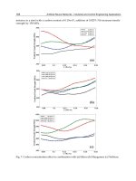
Van Swaaij and Zuiderweg (1972) used the ozone decomposition
reaction to study the conversion characteristics in a bubbling bed. Studies
were made with beds of 5, 10, 23, 30 and 60 cm diameter and up to 300 cm
bed heights. The results were compared with predictions using a two-
phase flow model with the mass transfer coefficient between the bubble
and dense phase derived from residence time distribution results of gas-
tracer pulse response tests. Figure 5 shows the height of the mass transfer
unit H
α
, which is equivalent to u/α where α is the mass transfer coeffi-
cient, as a function of the bed diameter. The results from the ozone
conversion and the residence time distribution interpreted by the two
phase model gave reasonably similar results. In these cases, the mass
transfer between phases is the limiting resistance for the reaction. Note
that for larger bed diameters the mass transfer coefficient decreases. Van
Swaaij and Zuiderweg (1973) showed that the inclusion of vertical tubes
in a bed gave bubble to dense phase mass transfer results which were
roughly equivalent to a smaller open bed with the same hydraulic diameter
while the solids axial mixing was higher than that predicted using the
hydraulic diameter.
Figure 5. Mass transfer unit for ozone conversion for different bed diameters.
(From Van Swaaij and Zuiderweg, 1972.)
6 .FROM CONVERSION DATA
.O C o FR)M RTD TESTS
( PRESENT INVESTIGATION )
u
«{H
O.i
1
I
4
. .
I
4
D,m