Three phase a c circuits
Bạn đang xem bản rút gọn của tài liệu. Xem và tải ngay bản đầy đủ của tài liệu tại đây (684.04 KB, 32 trang )
Three-Phase A.C. Circuits
Chapter 3
Learning Outcomes
This chapter introduces the concepts and principles of the three-phase electrical supply, and the
corresponding circuits. On completion you should be able to:
1 Describe the reasons for, and the generation of the three-phase supply.
2 Distinguish between star (3 and 4-wire) and delta connections.
3 State the relative advantages of three-phase systems compared with single-phase-systems.
4 Solve three-phase circuits in terms of phase and line quantities, and the power developed in
three-phase balanced loads.
5 Measure power dissipation in both balanced and unbalanced three-phase loads, using the
1, 2 and 3-w
attmeter methods, and hence determine load power factor.
6 Calculate the neutral current in a simple unbalanced 4-wire system.
85
3.1 Generation of a Three-Phase Supply
In order to understand the reasons for, and the method of generating
a three-phase supply, let us fi rstly consider the generation of a single-
phase supply. Alternating voltage is provided by an a.c. generator,
more commonly called an alternator. The basic principle was outlined
in Fundamental Electrical and Electronic Principles, Chapter 5.
It was shown that when a coil of wire, wound on to a rectangular
former, is rotated in a magnetic fi eld, an alternating (sinusoidal)
voltage is induced into the coil. You should also be aware that for
electromagnetic induction to take place, it is the relative movement
between conductor and magnetic fl ux that matters. Thus, it matters not
whether the fi eld is static and the conductor moves, or vice versa.
For a practical alternator it is found to be more convenient to rotate the
magnetic fi eld, and to keep the conductors (coil or winding) stationary.
CH003-H8747.indd 85CH003-H8747.indd 85 4/10/2008 3:24:46 PM4/10/2008 3:24:46 PM
86
Further Electrical and Electronic Principles
In any rotating a.c. machine, the rotating part is called the rotor, and
the stationary part is called the stator. Thus, in an alternator, the fi eld
system is contained in the rotor
. The winding in which the emf is
generated is contained in the stator. The reasons for this are as follows:
In this context, the term fi eld refers to the magnetic fi eld. This fi eld is normally produced
by passing d.c. current through the rotor winding. Since the winding is rotated, the
current is passed to it via copper slip-rings on the shaft. The external d.c. supply is
connected to the slip-rings by a pair of carbon brushes.
(a) When large voltages are generated, heavy insulation is necessary.
If this e
xtra mass has to be rotated, the driving device has to
develop extra power. This will then reduce the overall effi ciency
of the machine. Incorporating the winding in the stator allows the
insulation to be as heavy as necessary, without adversely affecting
the effi ciency.
(b) The contact resistance between the brushes and slip-rings is very
small. Ho
wever, if the alternator provided high current output (in
hundreds of ampere), the I
2
R power loss would be signifi cant. The
d.c. current (excitation current) for the fi eld system is normally
only a few amps or tens of amps. Thus, supplying the fi eld current
via the slip-rings produces minimal power loss. The stator winding
is simply connected to terminals on the outside of the stator casing.
(c) For very small alternators, the rotor would contain permanent
magnets to pro
vide the rotating fi eld system. This then altogether
eliminates the need for any slip-rings. This arrangement is referred
to as a brushless machine.
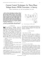
The basic construction for a single-phase alternator is illustrated in
Fig. 3.1 . The conductors of the stator winding are placed in slots
G
J
L
B
D
F
H
S
N
rotor
stator
K
M
A
C
E
Fig. 3.1
CH003-H8747.indd 86CH003-H8747.indd 86 4/10/2008 3:24:50 PM4/10/2008 3:24:50 PM
Three-Phase A.C. Circuits
87
around the inner periphery of the stator. The two ends of this winding
are then led out to a terminal block on the casing. The rotor winding
is also mounted in slots, around the circumference of the rotor. This
fi gure is used to illustrate the principle. A practical machine would
have many more conductors and slots.
Since the conductors of the stator winding are spread around the whole
of the slots, it is known as a distributed winding. As the rotor fi eld
sweeps past these conductors an emf is induced in each of them in turn.
These individual emfs reach their maximum values only at the instant
that the rotating fi eld ‘ cuts ’ them at 90°. Also, since the slots have an
angular displacement between them, then the conductor emfs will be
out of phase with each other by this same angle. In Fig. 3.1 there are a
total of twelve conductors, so this phase difference must be 30°. The
total stator winding emf will therefore not be the arithmetic sum of the
conductor emfs, but will be the phasor sum, as shown in Fig. 3.2 . The
ratio of the phasor sum to the arithmetic sum is called the distribution
factor. For the case shown (a fully distributed winding) the distribution
factor is 0.644.
30Њ
E
F
G
H
L
K
M
J
D
C
B
A
AB, CD etc. are conductor (coil) emfs.
AM is the phasor sum
Fig. 3.2
Now, if all of the stator conductors could be placed into a single pair
of slots, opposite to each other, then the induced emfs would all be
in phase. Hence the phasor and arithmetic sums would be the same,
yielding a distribution factor of unity. This is not a practical solution.
However, if the conductors are concentrated so as to occupy only one
third of the available stator slots, then the distribution factor becomes
0.966. In a practical single-phase alternator, the stator winding is
distributed over two thirds of the slots.
Let us return to the option of using only one third of the slots. We will
now have the space to put two more identical windings into the stator.
Each of the three windings could be kept electrically separate, with
their own pairs of terminals. We would then have three separate single-
phase alternators in the same space as the original. Each of these would
CH003-H8747.indd 87CH003-H8747.indd 87 4/10/2008 3:24:50 PM4/10/2008 3:24:50 PM
88
Further Electrical and Electronic Principles
also have a good distribution factor of 0.966. The three winding emfs
will of course be mutually out of phase with each other by 120°, since
each whole winding will occupy 120° of stator space. What we now
have is the basis of a three-phase alternator.
The term three-phase alternator is in some ways slightly misleading.
What we have, in effect, are three identical single-phase alternators
contained in the one machine. The three stator windings are brought
out to their own separate pairs of terminals on the stator casing. These
stator windings are referred to as phase windings, or phases. They
are identifi ed by the colours red, yellow and blue. Thus we have the
red, yellow and blue phases. The circuit representation for the stator
winding of such a machine is shown in Fig. 3.3 . In this fi gure, the three
phase windings are shown connected, each one to its own separate
load. This arrangement is known as a three-phase, six-wire system.
However, three-phase alternators are rarely connected in this way.
LOAD 2
LOAD 1
LOAD 3
Fig. 3.3
voltage
V
R
0
180 360 θ (deg)
V
Y
V
B
Fig. 3.4
Since the three generated voltages are sinewaves of the same
frequency, mutually out-of-phase by 120°, then they may be
represented both on a waveform diagram using the same angular or
time axis, and as phasors. The corresponding waveform and phasor
diagrams are shown in Figs. 3.4 and 3.5 respectively. In either case,
CH003-H8747.indd 88CH003-H8747.indd 88 4/10/2008 3:24:51 PM4/10/2008 3:24:51 PM
Three-Phase A.C. Circuits
89
we need to select a reference phasor. By convention, the reference is
always taken to be the red phase voltage. The yellow phase lags the
red by 120°, and the blue lags the red by 240° (or, if you prefer, leads
the red by 120°). The windings are arranged so that when the rotor is
driven in the chosen direction, the phase sequence is red, yellow, blue.
If, for any reason, the rotor was driven in the opposite direction, then
the phase sequence would be reversed, i.e. red, blue, yellow. We shall
assume that the normal sequence of R, Y, B applies at all times.
It may be seen from the waveform diagram that at any point along the
horizontal axis, the sum of the three voltages is zero. This fact becomes
even more apparent if the phasor diagram is redrawn as in Fig. 3.6 . In
this diagram, the three phasors have been treated as any other vector
quantity. The sum of the vectors may be determined by drawing them
to scale, as in Fig. 3.6 , and the resultant found by measuring the
distance and angle from the beginning point of the fi rst vector to the
arrowhead of the last one. If, as in Fig. 3.6 , the fi rst and last vectors
meet in a closed fi gure, the resultant must be zero.
V
R
V
Y
V
B
Fig. 3.5
V
R
V
B
V
Y
Fig. 3.6
3.2 Three-Phase, Four-Wire System
It is not necessary to have six wires from the three phase windings to
the three loads, provided there is a common ‘ return ’ line. Each winding
will have a ‘ start ’ (S) and a ‘ fi nish ’ (F) end. The common connection
mentioned above is achieved by connecting the corresponding ends
CH003-H8747.indd 89CH003-H8747.indd 89 4/10/2008 3:24:51 PM4/10/2008 3:24:51 PM
90
Further Electrical and Electronic Principles
of the three phases together. For example, either the three ‘ F ’ ends or
the three ‘ S ’ ends are commoned. This form of connection is shown
in Fig. 3.7 , and is known as a star or Y connection. With the resulting
4-wire system, the three loads also are connected in star confi guration.
The three outer wires are called the lines, and the common wire in the
centre is called the neutral.
S
F
S
S
F
F
Fig. 3.7
If the three loads were identical in every way (same impedance and
phase angle), then the currents fl owing in the three lines would be
identical. If the waveform and/or phasor diagrams for these currents
were drawn, they would be identical in form to Figs. 3.4 and 3.5 . These
three currents meet at the star point of the load. The resultant current
returning down the neutral wire would therefore be zero. The load in
this case is known as a balanced load, and the neutral is not strictly
necessary. However it is diffi cult, in practice, to ensure that each of
the three loads are exactly balanced. For this reason the neutral is left
in place. Also, since it has to carry only the relatively small ‘ out-of-
balance ’ current, it is made half the cross-sectional area of the lines.
Let us now consider one of the advantages of this system compared
with both a single-phase system, and the three-phase 6-wire system.
Suppose that three identical loads are to be supplied with 200 A each.
The two lines from a single-phase alternator would have to carry the
total 600 A required. If a 3-phase, 6-wire system was used, then each
line would have to carry only 200 A. Thus, the conductor csa would
only need to be 1/3 that for the single-phase system, but of course,
being six lines would entail using the same total amount of conductor
material. If a 4-wire, 3-phase system is used there will be a saving on
conductor costs in the ratio of 3.5:6 (the 0.5 being due to the neutral).
If the power has to be sent over long transmission lines, such as the
National Grid System, then the 3-phase, 4-wire system yields an
enormous saving in cable costs. This is one of the reasons why the
power generating companies use three-phase, star-connected generators
to supply the grid system.
CH003-H8747.indd 90CH003-H8747.indd 90 4/10/2008 3:24:51 PM4/10/2008 3:24:51 PM
Three-Phase A.C. Circuits
91
3.3 Relationship between Line and Phase Quantities in a
Star-connected System
Consider Fig. 3.8 , which represents the stator of a 3-phase alternator
connected to a 3-phase balanced load. The voltage generated by each
of the three phases is developed between the appropriate line and the
neutral. These are called the phase voltages, and may be referred to in
general terms as V
ph
, or specifi cally as V
RN
, V
YN
and V
BN
respectively.
However, there will also be a difference of potential between any pair
of lines. This is called a line voltage, which may be generally referred
to as V
L
, or specifi cally as V
RY
, V
YB
arid V
BR
respectively.
I
L
V
L
I
N
I
L
V
ph
V
ph
V
ph
V
L
V
L
I
ph
I
ph
I
ph
R
N
B
Y
Fig. 3.8
V
YN
V
BN
ϪV
YN
C
B
0
A
V
RN
30Њ
30Њ
Fig. 3.9
A line voltage is the phasor difference between the appropriate pair
of phase voltages. Thus, V
RY
is the phasor difference between V
RN
and V
YN
. In terms of a phasor diagram, the simplest way to subtract
one phasor from another is to reverse one of them, and then fi nd the
resulting phasor sum. This is, mathematically, the same process as
saying that a Ϫ b ϭ a ϩ ( Ϫ b). The corresponding phasor diagram is
shown in Fig. 3.9 .
CH003-H8747.indd 91CH003-H8747.indd 91 4/10/2008 3:24:51 PM4/10/2008 3:24:51 PM
92
Further Electrical and Electronic Principles
Note : If V
YN
is reversed, it is denoted either as Ϫ V
YN
or as V
NY
. We
shall use the fi rst of these.
The phasor difference between V
RN
and V
YN
is simply the phasor sum
of V
RN
ϩ ( ϪV
YN
). Geometrically this is obtained by completing the
parallelogram as shown in Fig. 3.9 . This parallelogram consists of two
isosceles triangles, such as OCA. Another property of a parallelogram is
that its diagonals bisect each other at right angles. Thus, triangle OCA
consists of two equal right-angled triangles, OAB and ABC. This is
illustrated in Fig. 3.10 . Since triangle OAB is a 30°, 60°, 90° triangle,
then the ratios of its sides AB:OA:OB will be 1:2:Ί3
–
respectively.
B
30°
60°
OA
C
Fig. 3.10
Hence,
OB
OA
so OB
OA
but OC OB OA
and since OC ,
ϭ
ϭ
ϭϫ ϭ
ϭ
3
2
3
2
23
.
.
V
RY
and OA
then
ϭ
ϭ
V
VV
RN
RY RN
3
Using the same technique, it can be shown that:
VVVV
YB YN BR BN
ϭϭ33 and
Thus, in star configuration, VV
Lph
ϭ 3
(3.1)
The complete phasor diagram for the line and phase voltages for a star
connection is shown in Fig. 3.11 . Also, considering the circuit diagram
of Fig. 3.8 , the line and phase currents must be the same.
Hence, in star configuration, II
Lph
ϭ
(3.2)
We now have another advantage of a 3-phase system compared with
single-phase. The star-connected system provides two alternative
voltage outputs from a single machine. For this reason, the stators
of all alternators used in electricity power stations are connected in
star confi guration. These machines normally generate a line voltage
CH003-H8747.indd 92CH003-H8747.indd 92 4/10/2008 3:24:52 PM4/10/2008 3:24:52 PM
Three-Phase A.C. Circuits
93
of about 25 kV. By means of transformers, this voltage is stepped up
to 400 kV for long distance transmission over the National Grid. For
more localised distribution, transformers are used to step down the
line voltage to 132 kV, 33 kV, 11 kV, and 415 V. The last three of these
voltages are supplied to various industrial users. The phase voltage
derived from the 415 V lines is 240 V, and is used to supply both
commercial premises and households.
Worked Example 3.1
Q A 4 15 V, 50 Hz, 3-phase supply is connected to a star-connected balanced load. Each phase of the load
consists of a resistance of 25 and inductance 0.1 H, connected in series. Calculate (a) phase voltage,
(b) the line current drawn from the supply, and (c) the power dissipated.
A
Whenever a three-phase supply is speci ed, the voltage quoted is always the
line voltage. Also, since we are dealing with a balanced load, then it is necessary
only to calculate values for one phase of the load. The gures for the other two
phases and lines will be identical to these.
V
L
ϭ 4 15 V ; f ϭ 5 0 H z ; R
ph
ϭ 2 5 ; L
ph
ϭ 0.1 H
I
L
ϭ I
ph
V
L
0.1H
V
ph
25Ω
Fig. 3.12
V
BN
V
RN
V
RY
V
BR
V
YN
V
YB
30°
30°
30°
Fig. 3.11
CH003-H8747.indd 93CH003-H8747.indd 93 4/10/2008 3:24:52 PM4/10/2008 3:24:52 PM
94
Further Electrical and Electronic Principles
(a)
V
V
V
ph
L
ph
ϭϭ
ϭ
3
45
3
240
1
so V Ans
(b) Since it is possible to determine the impedance of a phase of the load, and
w
e now know the phase voltage, then the phase current may be calculated:
XfL
X
ZRX
L
L
ph
ph
L
ϭϭϫϫ
ϭ
ϭϩ ϭ ϩ
22500
342
25 3
22 2
ohm
hence
ohm
.
.
1
1
11
1
1
.
.
.
.
42
40 5
240
40 5
598
2
Z
V
Z
ph
ph
ph
ph
ph
ϭ
ϭϭ
ϭ
I
I
amp
so A
In a star-connected circuit, I
L
ϭ I
Ph
therefore I
L
ϭ 5.98 A Ans
The power in one phase, wattPR
P
ph
ph
ph
ph
ϭ
ϭϫ
ϭ
I
2
2
598 25
893 2
.
.99W
and since there are three phases, then the total power is:
PP
P
ph
ϭϫ ϭϫ
ϭ
3 3 893 29
268
watt
hence kW
.
. Ans
3.4 Delta or Mesh Connection
If the start end of one winding is connected to the fi nish end of the
next, and so on until all three windings are interconnected, the result
is the delta or mesh connection. This connection is shown in Fig. 3.13 .
The delta connection is not reserved for machine windings only, since
a 3-phase load may also be connected in this way.
I
L
I
L
V
L
I
ph
I
ph
I
ph
I
L
SF
F
F
S
S
Fig. 3.13
CH003-H8747.indd 94CH003-H8747.indd 94 4/10/2008 3:24:53 PM4/10/2008 3:24:53 PM
Three-Phase A.C. Circuits
95
3.5 Relationship between Line and Phase Quantities in a
Delta-connected System
It is apparent from Fig. 3.13 that each pair of lines is connected across
a phase winding. Thus, for the delta connection:
VV
Lph
ϭ
(3.3)
It is also apparent that the current along each line is the phasor
difference of a pair of phase currents. The three phase currents are
mutually displaced by 120°, and the phasor diagram for these is shown
in Fig. 3.14 . Using exactly the same geometrical technique as that for
the phase and line voltages in the star connection, it can be shown that:
II
Lph
ϭ 3
(3.4)
I
B(ph)
I
Y(ph)
I
R(ph
)
120°
120°
120°
Fig. 3.14
The phasor diagram for the phase and line currents in delta connection
is as in Fig. 3.15 . Note that the provision of a neutral wire is not
applicable with a delta connection. However, provided that the load
I
L
I
L
I
L
I
ph
I
ph
I
ph
30°
30°
30°
Fig. 3.15
CH003-H8747.indd 95CH003-H8747.indd 95 4/10/2008 3:24:53 PM4/10/2008 3:24:53 PM
96
Further Electrical and Electronic Principles
is balanced, there is no requirement for one. Under balanced load
conditions the three phase currents will be equal, as will be the three
line currents. If the load is unbalanced, then these equalities do not
exist, and each phase or line current would have to be calculated
separately. This technique is beyond the scope of the syllabus you are
now studying.
Worked Example 3.2
Q A balanced load of phase impedance 12 0 is connected in delta. When this load is connected to a
600 V, 50 Hz, 3-phase supply, determine (a) the phase current, and (b) the line current drawn.
A
Z
ph
ϭ 120 ; V
L
ϭ 600 V; f ϭ 5 0 H z
The circuit diagram is shown in Fig. 3.16 .
I
L
I
ph
V
L
ϭ V
ph
600V
Z
120Ω
Fig. 3.16
(a)
In delta, V
amp
so, A
VV
V
Z
ph L
ph
ph
ph
ph
ϭϭ
ϭϭ
ϭ
600
600
20
5
I
I
1
Ans
(b)
in delta, amp
therefore A
II
I
Lph
L
ϭϭϫ
ϭ
335
866. Ans
3.6 Power Dissipation in Star and Delta-connected Loads
We have seen in Example 3.1 that the power in a 3-phase balanced
load is obtained by multiplying the power in one phase by 3. In many
practical situations, it is more convenient to work with line quantities.
P
ph
ϭ V
ph
I
ph
cos φ watt
where cos φ is the phase power factor.
total power,
cos watt
PP
VI
ph
ph ph
ϭϫ
ϭϫ
3
31φ []
CH003-H8747.indd 96CH003-H8747.indd 96 4/10/2008 3:24:54 PM4/10/2008 3:24:54 PM
Three-Phase A.C. Circuits
97
Considering a STAR-connected load,
V
V
II
ph
L
ph L
ϭϭ
3
, and
Substituting for V
ph
and I
ph
in eqn [1]:
P
V
I
L
L
ϭϫ3
3
cos φ
therefore cos wattPVI
LL
ϭ 3 φ
(3.5)
For a delta-connected load,
VV I
I
ph L ph
ph
ϭϭ and
3
and substituting these values into eqn [1] will yield the same result
as shown in (3.5) above. Thus, the equation for determining power
dissipation, in both star and delta-connected loads is exactly the
same. However, the value of power dissipated by a given load when
connected in star is not the same as when it is connected in delta. This
is demonstrated in the following example.
Worked Example 3.3
Q A balanced load of phase impedance 10 0 and power factor 0.8 is connected (a) in star, and (b) in
delta, to a 400 V, 3-phase supply. Calculate the power dissipation in each case.
A
Z
ph
ϭ 10 0 ; cos φ ϭ 0.8; V
L
ϭ 4 0 0 V
(a) the cir
cuit diagram is shown in Fig. 3.17
V
L
400V
Z
100Ω
V
ph
I
L
ϭ I
ph
Fig. 3.17
CH003-H8747.indd 97CH003-H8747.indd 97 4/10/2008 3:24:54 PM4/10/2008 3:24:54 PM
98
Further Electrical and Electronic Principles
V
V
V
V
Z
ph
L
ph
Lph
ph
ph
L
ϭϭ
ϭ
ϭϭ ϭ
3
400
3
23
23
00
volt
so V
amp
and
1
1
1
II
I
ϭϭ
ϭϭϫϫϫ
ϭ
23
3 3 400 23 08
28
.
.
1
1
1
A
cos watt
therefore kW
PV
P
LL
I φ
Ans
(b) The circuit diagram is shown in Fig. 3.18
.
I
L
I
ph
V
L
ϭ V
ph
400V
Z
100Ω
Fig. 3.18
VV
V
Z
ph L
ph
ph
ph
ph
Lph
ϭϭ
ϭϭ
ϭ
ϭϭϫ
400
400
00
4
334
V
amp
so A
but
so
I
I
II
1
A
cos watt
therefore
I
I
L
LL
PV
P
ϭ
ϭϭϫϫϫ
ϭ
693
3 3 400 6 93 0 8
38
.
.
φ
44kW Ans
Comparing the two answers for the power dissipation in the above
example, it may be seen that:
Power in a delta-connected load is
that when i
three times
tt is connected in star configuration.
(3.6)
Worked Example 3.4
Q A balanced star-connected load is fed from a 400 V, 50 Hz, three-phase supply. The resistance in each
phase of the load is 10 and the load draws a total power of 15 kW. Calculate (a) the line current
drawn, (b) the load power factor, and (c) the load inductance.
A
V
L
ϭ 4 0 0 V ; f ϭ 5 0 H z ; R ϭ 10 ; P ϭ 15 000 W
CH003-H8747.indd 98CH003-H8747.indd 98 4/10/2008 3:24:54 PM4/10/2008 3:24:54 PM
Three-Phase A.C. Circuits
99
(a) The power in one phase will be one third of the total power, so
P
P
PR
P
R
ph
ph
ph
Lph
ph
ϭϭϭ
ϭ
ϭϭ ϭ
3
5 000
3
5
2
watt
kW
but, watt
so,
1
I
II
55000
0
22 36
1
I
L
ϭ .A Ans
(b
)
PV
P
V
LL
LL
ϭ
ϭϭ ϭ
ϫϫ
3
3
5 000
3 400 22 36
I
I
cos watt
so, cos p.f.
φ
φ
1
.
hhence, p.f. ϭ 0 968. Ans
(c)
φ
φ
ϭϭЊ
ϭϭ
ϭϫ ϭ
Ϫ
cos
tan
so,
1
1
1
11
0 968 4 47
0 258
0 0 258 2
.
.
X
R
X
ph
ph
ph
.
.
58
2
258
100
822
1
1
L
X
f
L
L
ϭϪ ϭ
ϭ
ohm
and mH Ans
400V
V
L
R
L
10Ω
Fig. 3.19
φ
Z
ph
X
ph
R
ph
Fig. 3.20
CH003-H8747.indd 99CH003-H8747.indd 99 4/10/2008 3:24:55 PM4/10/2008 3:24:55 PM
100
Further Electrical and Electronic Principles
Worked Example 3.5
Q A balanced delta-connected load takes a phase current of 15 A at a power factor of 0.7 lagging when
connected to a 115 V, 50 Hz, three-phase supply. Calculate (a) the power drawn from the supply, and
(b) the resistance in each phase of the load.
A
V
L
ϭ V
ph
ϭ 115 V ; f ϭ 5 0 H z ; I
ph
ϭ 15 A; cos φ ϭ 0.7
(a)
II
I
I
Lph
L
LL
PV
ϭϭϫ
ϭ
ϭϭϫϫϫ
335
25 98
33525980
amp
A
cos watt
1
11
.
φ 77
3622 5so W P ϭ . Ans
(b)
P
P
PR
R
P
ph
ph
ph
ph
ph
ϭϭ ϭ
ϭ
ϭϭ
3
3622 5
3
207 5
2
2
.
.1
1
W
and watt
so ohm
I
I
2207 5
5
537
2
.
.
1
R ϭ Ans
3.7 Star/Delta Supplies and Loads
As explained in Section 3.3, the distribution of 3-phase supplies is
normally at a much higher line voltage than that required for many
users. Hence, 3-phase transformers are used to step the voltage down
to the appropriate value. A three-phase transformer is basically three
single-phase transformers interconnected. The three primary windings
may be connected either in star or delta, as can the three secondary
windings. Similarly, the load connected to the transformer secondary
windings may be connected in either confi guration. One important
point to bear in mind is that the transformation ratio (voltage or turns
ratio) refers to the ratio between the primary phase to the secondary
phase winding. The method of solution of this type of problem is
illustrated in the following worked example.
115 V
V
L
ϭ V
ph
R
L
I
L
I
ph
ϭ 15 A
Fig. 3.21
CH003-H8747.indd 100CH003-H8747.indd 100 4/10/2008 3:24:55 PM4/10/2008 3:24:55 PM
Three-Phase A.C. Circuits
101
Worked Example 3.6
Q Figure 3.22 shows a balanced, star-connected load of phase impedance 25 and power factor
0.75, supplied from the delta-connected secondary of a 3-phase transformer. The turns ratio of the
transformer is 20:1, and the star-connected primary is supplied at 11 kV. Determine (a) the voltages
V
2
, V
3
and V
4
, (b) the currents I
1
, I
2
, and I
3
, and (c) the power drawn from the supply.
I
1
I
2
I
3
V
3
V
4
Zϭ 25Ω
cosφϭ0.75
V
2
20:1
V
1
11kV
Fig. 3.22
A
V
1
ϭ 11 000 V; N
p
/N
s
ϭ 20/1; Z
ph
ϭ 2 5 ; cos φ ϭ 0.75
(a)
V
V
V
V
V
N
N
V
NV
N
s
p
s
p
2
1
2
3
2
3
2
3
11 000
3
6 351
635
ϭϭ
ϭ
ϭ
ϭϭ
kV
so volt
. Ans
11
20
317 45
3
317 45
3
183 3
3
4
3
4
hence V
and V
V
V
V
V
ϭ
ϭϭ
ϭ
.
.
.
Ans
Ans
(b) In order to calculate the currents, we shall have to start with the load, and
w
ork ‘ back ’ through the circuit to the primary of the transformer:
I
I
I
I
I
I
3
4
3
2
3
2
83 3
25
733
3
733
3
423
ϭϭ
ϭ
ϭϭ
ϭ
V
Z
ph
amp
A
A
1
1
.
.
.
.
Ans
Ans
II
I
I
I
2
2
423
20
02 2
ϭ
ϭϭ
ϭ
N
N
N
N
s
p
s
p
so amp
hence A
1
1
1
.
. Ans
CH003-H8747.indd 101CH003-H8747.indd 101 4/10/2008 3:24:55 PM4/10/2008 3:24:55 PM
102
Further Electrical and Electronic Principles
(c)
PV
P
ϭ
ϭϫϫ ϫ ϫ
ϭ
3
30022075
302
3
cos watt
therefore kW
11
11 1 1
I φ
. AAns
Worked Example 3.7
Q The star-connected stator of a three-phase, 50 Hz alternator supplies a balanced delta-connected
load. Each phase of the load consists of a coil of resistance 15 and inductance 36 mH, and the phase
voltage generated by the alternator is 231 V. Calculate (a) the phase and line currents, (b) the load
power factor, and (c) the power delivered to the load.
A
f ϭ 50 Hz; R ϭ 15 ; L ϭ 36 mH; V
ph
ϭ 231 V
R
L
I
2
I
1
V
2
36 mH
15 Ω
V
1
231 V
Fig. 3.23
(a)
F
or the alternator:
VV
VV V
V
ph
Lph
ph L
1
1
1ϭϭ
ϭϭ
ϭ
ϭϭ
23 V
V
2
2
3
400
III
For the load:
VVV
XfL
X
ZRX
Lph
L
L
ph L
2
3
2
200360
3
ϭϭ ϭ
ϭϭϫϫϫ
ϭ
ϭϩ
Ϫ
400 V
ohm
11
11 1.
2222
2
2
53
879
400
879
2
ohm
amp
ϭϩ
ϭ
ϭϭ ϭ
ϭ
1111
1
1
1
.
.
.
Z
V
Z
ph
ph
ph
ph
II
I
.
.
29
33229
36 88
2
A
A
Ans
Ans
II I
I
L
ϭϭ ϭ ϫ
ϭ
1
1
1
(b)
p.f. cos
p.f. lagging
ϭϭ
ϭ
ϭ
φ
R
Z
1
1
5
879
08
.
. Ans
CH003-H8747.indd 102CH003-H8747.indd 102 4/10/2008 3:24:56 PM4/10/2008 3:24:56 PM
Three-Phase A.C. Circuits
103
(c)
PV
P
LL
ϭϭϫϫϫ
ϭ
3 3 400 36 88 0 8
20 4
I cos watt
kW
Alternativel
φ
. Ans
yy, watt
kW
PP R
P
ph
ϭϫ ϭϫ
ϭϫ ϫ
ϭ
33
3229 5
20 4
2
2
2
I
11.
. Ans
3.8 Measurement of Three-phase Power
In an a.c. circuit the true power may only be measured directly by
means of a wattmeter. The principle of operation of this instrument
is described in Fundamental Electrical and Electronic Principles,
Chapter 5. As a brief reminder, the instrument has a fi xed coil through
which the load current fl ows, and a moving voltage coil (or pressure
coil) connected in parallel with the load. The defl ection of the pointer,
carried by the moving coil, automatically takes into account the
phase angle (or power factor) of the load. Thus the wattmeter reading
indicates the true power, P ϭ VI cos φ watt.
If a three-phase load is balanced, then it is necessary only to measure
the power taken by one phase. The total power of the load is then
obtained by multiplying this fi gure by three. This technique can be
very simply applied to a balanced, star-connected system, where the
star point and/or the neutral line are easily accessible. This is illustrated
in Fig. 3.24 .
R
N
B
Y
W
1
Fig. 3.24
In the situation where the star point is not accessible, then an artifi cial
star point needs to be created. This is illustrated in Fig. 3.25 , where
the value of the two additional resistors is equal to the resistance of the
wattmeter voltage coil.
In the case of an unbalanced star-connected load, one or other of the
above procedures would have to be repeated for each phase in turn.
The total power P ϭ P
1
ϩ P
2
ϩ P
3
, where P
1
, P
2
and P
3
represent the
three separate readings.
CH003-H8747.indd 103CH003-H8747.indd 103 4/10/2008 3:24:56 PM4/10/2008 3:24:56 PM
104
Further Electrical and Electronic Principles
For a delta-connected load, the procedure is not quite so simple.
The reason is that the phase current is not the same as the line current.
Thus, if possible, one of the phases must be disconnected to allow
the connection of the wattmeter current coil. This is shown in
Fig. 3.26 . Again, if the load was unbalanced, this process would have
to be repeated for each phase.
W
1
R
B
Y
RR
Fig. 3.25
W
1
R
B
Y
Fig. 3.26
3.9 The Two-Wattmeter Method
The measurement of three-phase power using the above methods can
be very awkward and time-consuming. In practical circuits, the power
is usually measured by using two wattmeters simultaneously, as shown
in Fig. 3.27 .
The advantages of this method are:
(a) Access to the star point is not required.
(b) The power dissipated in both balanced and unbalanced loads is
obtained, without an
y modifi cation to the connections.
(c) For balanced loads, the power factor may be determined.
CH003-H8747.indd 104CH003-H8747.indd 104 4/10/2008 3:24:57 PM4/10/2008 3:24:57 PM
Three-Phase A.C. Circuits
105
Considering Fig. 3.27 , the following statements apply:
Instantaneous power for watt
and for ,
1
22
Wp v i
Wp v
RB R
YB
,
1
ϭ
ϭ ii
pp
vi vi
Y
RB R YB Y
watt
total instantaneous power
]
ϭϩ
ϭϩ
12
1………[
Now, any line voltage is the phasor difference between the appropriate
pair of phase voltages, hence:
vvv vvv
RB RN BN YB YN BN
ϭϪ ϭϪ and
and substituting these into eqn [1] yields:
ppiv v iv v
vi vi v i i
i
RRN BN YYN BN
RN R YN Y BN R Y
12
ϩϭ Ϫ ϩ Ϫ
ϭϩϪ ϩ
()()
()
but,
RRY B
iiϩϭϪ
i.e. the phasor sum of three equal currents is zero.
therefore p p vi vi vi
RN R YN Y BN B12
ϩϭ ϩ ϩ
The instantaneous sum of the powers measured by the two wattmeters
is equal to the sum of instantaneous power in the three phases.
Hence, total power,
PPP P P P
RY B
ϭϩ ϭ ϩ ϩ
12
watt
(3.7)
Consider now the phasor diagram for a resistive-inductive balanced
load, with the two wattmeters connected as in Fig. 3.27 . This phasor
diagram appears as Fig. 3.28 , below.
W
1
W
2
I
B
I
Y
V
RB
V
YB
I
R
R
B
Y
Fig. 3.27
CH003-H8747.indd 105CH003-H8747.indd 105 4/10/2008 3:24:57 PM4/10/2008 3:24:57 PM
106
Further Electrical and Electronic Principles
The power indicated by W
1
,
PVI
LL1
ϭЊϪcos (30 )φ
(3.8)
and that for W
2
,
PVI
LL2
ϭЊϩ cos (30 )φ
(3.9)
From these results, and using Fig. 3.29 , the following points should be
noted:
I
B
φ
φ
φ
V
BR
V
BN
V
R
V
RN
V
RB
V
YN
V
YB
I
Y
I
R
(30° ϩ φ)
(30° Ϫ φ)
Fig. 3.28
wattmeter
readings
ϩ
Ϫ
Ϫ90 Ϫ30 30
90 150
(30° Ϯ φ)
Fig. 3.29
1 If the load p.f. Ͼ 0.5 (i.e. φ Ͻ 60°); both meters will give a positive
reading.
2 If the load p.f. ϭ
0.5 (i.e. φ ϭ 60°); W
1
indicates the total power,
and W
2
indicates zero.
3 If the load p.f. Ͻ 0.5
(i.e. φ Ͼ 60°); W
2
attempts to indicate a
negative reading. In this case, the connections to the voltage coil
CH003-H8747.indd 106CH003-H8747.indd 106 4/10/2008 3:24:57 PM4/10/2008 3:24:57 PM
Three-Phase A.C. Circuits
107
of W
2
need to be reversed, and the resulting reading recorded as a
negative value. Under these circumstances, the total load power will
be P ϭ P
1
Ϫ P
2
.
4 The load power factor may be determined from the two wattmeter
readings from the equation:
φ ϭ
Ϫ
ϩ
Ϫ
tan
1
21
21
3
PP
PP
⎛
⎝
⎜
⎜
⎜
⎜
⎞
⎠
⎟
⎟
⎟
⎟
(3.10)
hence, power factor, cos φ can be determined.
Worked Example 3.8
Q The power in a 3-phase balanced load was measured, using the two-wattmeter method. The recorded
readings were 3.2 kW and 5 kW respectively. Determine the load power and power factor .
A
PP
PPP
P
1
1
ϭϭ
ϭϩ ϭ ϩ
ϭ
32 5
32
82
2
2
.
.
.
kW; kW
watt ( 5) kW
therefore, kW
AAns
φ ϭ
Ϫ
ϩ
ϭ
Ϫ
ϩ
Ϫ
Ϫ
tan
tan
1
1
1
1
3
3
532
532
2
2
PP
PP
⎛
⎝
⎜
⎜
⎜
⎜
⎞
⎠
⎟
⎟
⎟
⎟
⎟
⎛
⎝
⎜
⎜
⎜
⎞
.
.
⎠⎠
⎟
⎟
⎟
⎟
hence,
and p.f. cos
φ
φ
ϭЊ
ϭϭ
20 82
0 935
.
. Ans
Worked Example 3.9
Q A 3-phase balanced load takes a line current of 24 A at a lagging power factor of 0.42, when connected
to a 415 V, 50 Hz supply. If the power dissipation is measured using the two-wattmeter method,
determine the two wattmeter readings, and the value of power dissipated. Comment on the results.
A
I
L
ϭ 24 A; cos φ ϭ 0.42; V
L
ϭ 4 15 V
φ
φ
ϭϭЊ
ϭЊϪ
ϭϫϫ Ϫ
Ϫ
cos
cos (30 ) watt
cos (
1
1
1
1
042 65 7
45 24
PV
LL
I
335 7
842
30
2
.
.
1
1
1
Њ
ϭ
ϭЊϩ
ϭ
)
therefore, kW
cos ( ) watt
P
PV
LL
Ans
I φ
44 5 24 95 7
896 7
2
2
11
1
ϫϫ Њ
ϭϪ
ϭϩ ϭ
cos ( )
therefore, W
watt
.
.P
PP P
Ans
88 42 896 7
7 244
1 ϩϪ
ϭ
()
hence, kW
.
.P Ans
To obtain the negative reading on W
2
, the connections to its voltage coil must
have been reversed.
CH003-H8747.indd 107CH003-H8747.indd 107 4/10/2008 3:24:58 PM4/10/2008 3:24:58 PM
108
Further Electrical and Electronic Principles
Worked Example 3.10
Q A delta-connected load has a phase impedance of 10 0 at a phase angle of 55°, and is connected to a
415 V three-phase supply. The total power consumed is measured using the two-wattmeter method.
Determine the readings on the two meters and hence calculate the power consumed .
A
Z
ph
ϭ 10 0 ; φ ϭ 55°; V
L
ϭ 4 15 V ϭ V
ph
V
L
415V
V
L
415V
I
L
I
L
W
1
W
2
Z
ph
100Ω
Fig. 3.30
I
II
I
ph
ph
ph
Lph
LL
V
Z
PV
ϭϭϭ
ϭϭϫϭ
ϭ
amp A
A
c
45
00
45
3 3 45 79
1
1
1
11
1
.
oos ( ) watt cos
kW
cos
30 4 5 7 9 25
2 704
2
ЊϪ ϭ ϫ ϫ Ϫ Њ
ϭ
ϭ
φ 11
1
.
.P
PV
LL
Ans
I () watt cos 85
W
watt
30 4 5 7 9
260
270
2
2
Њϩ ϭ ϫ ϫ Њ
ϭ
ϭϩ ϭ
φ 11
1
.
P
PP P
Ans
44 260
2 964
ϩ
ϭP .kW Ans
3 . 10 Neutral Current in an Unbalanced Three-phase Load
We have seen that the neutral current for a balanced load is zero. This is
because the phasor sum of three equal currents, mutually displaced by
120°, is zero. If the load is unbalanced, then the three line (and phase)
currents will be unequal. In this case, the neutral has to carry the resulting
out-of-balance current. This current is simply obtained by calculating the
phasor sum of the line currents. The technique is basically the same as
that used previously, by resolving the phasors into horizontal and vertical
components, and applying Pythagoras ’ theorem. The only additional fact
to bear in mind is that both horizontal and vertical components can have
negative values. This is illustrated by the following example.
CH003-H8747.indd 108CH003-H8747.indd 108 4/10/2008 3:24:58 PM4/10/2008 3:24:58 PM
Three-Phase A.C. Circuits
109
Worked Example 3.11
Q An unbalanced, star-connected load is supplied from a 3-phase, 415 V source. The three phase loads
are purely resistive. These loads are 25 , 3 0 and 40 , and are connected in the red, yellow and
blue phases respectively. Determine the value of the neutral current, and its phase angle relative to
the red phase current.
A
V
L
ϭ 415 V ; R
R
ϭ 2 5 ; R
Y
ϭ 3 0 ; R
B
ϭ 4 0
The circuit diagram is shown in Fig. 3.31.
V
ph
V
L
I
R
I
Y
I
B
I
N
R
Y
B
30Ω
40Ω
25Ω
Fig. 3.31
V
V
V
R
V
R
V
R
ph
L
R
ph
R
Y
ph
Y
B
ph
B
ϭϭϭ
ϭϭϭ
3
45
3
240 volt V
amp; amp;
1
III
amp
A A A
ϭϭϭ
ϭϭϭ
240
25
240
30
240
40
96 8 6III
RYB
.
The corresponding phasor diagrams are shown in Fig. 3.32 .
I
B
I
Y
I
R
I
N
V.C.
H.C.
φ
60°
60°
Fig. 3.32
CH003-H8747.indd 109CH003-H8747.indd 109 4/10/2008 3:24:58 PM4/10/2008 3:24:58 PM