IEC 61131 4 programmable controllers user guidelines
Bạn đang xem bản rút gọn của tài liệu. Xem và tải ngay bản đầy đủ của tài liệu tại đây (986.16 KB, 136 trang )
TECHNICAL
REPORT
IEC
TR 61131-4
Second edition
2004-07
Programmable controllers –
Part 4:
User guidelines
Reference number
IEC/TR 61131-4:2004(E)
Copyright International Electrotechnical Commission
Provided by IHS under license with IEC
Licensee=Technip Abu Dabhi/5931917101
Not for Resale, 02/12/2006 07:04:26 MST
No reproduction or networking permitted without license from IHS
``,`,`,,,``````,,``,,``,,,,`,-`-`,,`,,`,`,,`
Publication numbering
As from 1 January 1997 all IEC publications are issued with a designation in the
60000 series. For example, IEC 34-1 is now referred to as IEC 60034-1.
Consolidated editions
The IEC is now publishing consolidated versions of its publications. For example,
edition numbers 1.0, 1.1 and 1.2 refer, respectively, to the base publication, the
base publication incorporating amendment 1 and the base publication incorporating
amendments 1 and 2.
Further information on IEC publications
The technical content of IEC publications is kept under constant review by the IEC,
thus ensuring that the content reflects current technology. Information relating to
this publication, including its validity, is available in the IEC Catalogue of
publications (see below) in addition to new editions, amendments and corrigenda.
Information on the subjects under consideration and work in progress undertaken
by the technical committee which has prepared this publication, as well as the list
of publications issued, is also available from the following:
• IEC Web Site (www.iec.ch
)
• Catalogue of IEC publications
The on-line catalogue on the IEC web site (www.iec.ch/searchpub
) enables you to
search by a variety of criteria including text searches, technical committees
and date of publication. On-line information is also available on recently issued
publications, withdrawn and replaced publications, as well as corrigenda.
• IEC Just Published
This summary of recently issued publications (www.iec.ch/online_news/ justpub
)
is also available by email. Please contact the Customer Service Centre (see
below) for further information.
• Customer Service Centre
If you have any questions regarding this publication or need further assistance,
please contact the Customer Service Centre:
Email:
Tel: +41 22 919 02 11
Fax: +41 22 919 03 00
Copyright International Electrotechnical Commission
Provided by IHS under license with IEC
Licensee=Technip Abu Dabhi/5931917101
Not for Resale, 02/12/2006 07:04:26 MST
No reproduction or networking permitted without license from IHS
``,`,`,,,``````,,``,,``,,,,`,-`-`,,`,,`,`,,`
TECHNICAL
REPORT
IEC
TR 61131-4
Second edition
2004-07
Programmable controllers –
Part 4:
User guidelines
PRICE CODE
IEC 2004 Copyright - all rights reserved
No part of this publication may be reproduced or utilized in any form or by any means, electronic or
mechanical, including photocopying and microfilm, without permission in writing from the publisher.
International Electrotechnical Commission, 3, rue de Varembé, PO Box 131, CH-1211 Geneva 20, Switzerland
Telephone: +41 22 919 02 11 Telefax: +41 22 919 03 00 E-mail: Web: www.iec.ch
XF
For price, see current catalogue
Commission Electrotechnique Internationale
International Electrotechnical Commission
Межд
ународная Электротехническая Комиссия
Copyright International Electrotechnical Commission
Provided by IHS under license with IEC
Licensee=Technip Abu Dabhi/5931917101
Not for Resale, 02/12/2006 07:04:26 MST
No reproduction or networking permitted without license from IHS
``,`,`,,,``````,,``,,``,,,,`,-`-`,,`,,`,`,,`
– 2 – TR 61131-4 IEC:2004(E)
CONTENTS
FOREWORD 5
INTRODUCTION 7
1
General 8
1.1
Scope and object 8
1.2
Normative references 9
1.3
Use of this report 9
2
Terms and definitions 10
3
General recommendations for installation 11
3.1
Environmental conditions 11
3.2
Field wiring 11
3.3
Electromagnetic compatibility 12
3.4
User system markings 13
4
PLC in functional safety applications 13
4.1
Functional safety and safety-related-system concept 13
4.2
Using a PLC in a safety-related application 15
4.3
Requirements on PLCs in a safety-related system 16
4.4
Integration of PLC into a safety-related system 16
Annex A (informative) Overview of normative parts of IEC 61131 19
A.1
Overview of IEC 61131-1 19
A.2
Overview of IEC 61131-2 26
A.3
Overview of IEC 61131-3 59
A.4
(blank) 88
A.5
Overview of IEC 61131-5 88
A.6
(blank) 100
A.7
Overview of IEC61131-7 100
A.8
(blank) 107
Annex B (informative) Conformity to IEC 61131 and product certification 108
B.1
General 108
B.2
Conformity to standards 108
B.3
Declaration of conformity and certification 109
B.4
The inter-relation of standards to laws in European Community 109
B.5
CE-marking of PLCs in the European Union 111
B.6
Transition periods 113
B.7
Other juristictions 114
B.8
Reference documents 115
Annex C (informative) Use of PLC programming languages and examples 116
C.1
Preamble 116
C.2
Advance planning 116
C.3
Structure and organization 117
C.4
Use of PLC languages 120
Copyright International Electrotechnical Commission
Provided by IHS under license with IEC
Licensee=Technip Abu Dabhi/5931917101
Not for Resale, 02/12/2006 07:04:26 MST
No reproduction or networking permitted without license from IHS
``,`,`,,,``````,,``,,``,,,,`,-`-`,,`,,`,`,,`
TR 61131-4 IEC:2004(E) – 3 –
C.5
User Defined Function Block (DFB) 127
C.6
Language implementation 130
Figure 1 – Object of user guidelines 8
Figure 2 – SRS in risk reduction concept 14
Figure 3 – Event tree analysis for deployment of SRS 18
Figure A.1 – Basic functional structure of a PLC system 21
Figure A.2 – PLC hardware model 22
Figure A.3 – Typical interface/port diagram of a PLC system 23
Figure A.4 – Type test EUT configuration 32
Figure A.5 – Digital I/O parameters 35
Figure A.6 – Immunity zones 46
Figure A.7 – Programmable Controller System (PLC system) 59
Figure A.8 – Software model 62
Figure A.9 – Combination of programmable controller language elements 64
Figure A.10 – Examples of function usage 69
Figure A.11 – Function block instantiation examples 70
Figure A.12 – Sequential function chart 71
Figure A.13 – Function block and program declarations for configuration example 79
Figure A.14 – The four programming languages 82
Figure A.15 – Boolean OR examples 86
Figure A.16 – Programming elements of Function Block Diagram language 87
Figure A.17 – Top-down and bottom-up programming 88
Figure A.18 – Scope of IEC 61131-5 88
Figure A.19 – Relationship of the communication model to IEC 61131-2 and IEC 61131-3 90
Figure A.20 – Programmable controller communication model 91
Figure A.21 – Example of communication control in FBD language 99
Figure A.22 – Example of a fuzzy control in FBD program 101
Figure A.23 – Example of ramp curve membership functions 102
Figure A.24 – Defuzzification program block 102
Figure A.25 – Example of singleton terms 102
Figure C.1 – Program structure overview 118
Figure C.2 – Program structure with detail 119
Figure C.3 – The structured program plan for brewing process automation with various
languages 121
Figure C.4 – Example of a program in IL language 122
Figure C.5 – Example of a program in ST language 123
Figure C.6 – Example of a control program in LD language 124
Figure C.7 – An example of a control program in FBD language 125
Figure C.8 – A control program in SFC 126
Figure C.9 – A DFB for valve control 127
Figure C.10 – DFB for valve actuation 128
Figure C.11 – DFB for alarm actuation 129
Copyright International Electrotechnical Commission
Provided by IHS under license with IEC
Licensee=Technip Abu Dabhi/5931917101
Not for Resale, 02/12/2006 07:04:26 MST
No reproduction or networking permitted without license from IHS
``,`,`,,,``````,,``,,``,,,,`,-`-`,,`,,`,`,,`
– 4 – TR 61131-4 IEC:2004(E)
Table 1 – Environmental conditions 11
Table 2 – Installation rules: earthing measures 12
Table 3 – Installation rules: EMC 12
Table 4 – SIL of demand mode safety functions 14
Table 5 – SIL of continuous mode safety functions 14
Table A.1 – Summary of programmable functions 24
Table A.2 – General conditions for tests 32
Table A.3 – Operating ambient air temperature of PLC systems 33
Table A.4 – Emission limits 45
Table A.5 – Criteria to prove the performance of a PLC-system against EMC
disturbances 47
Table A.6 – Voltage drops and interruptions 47
Table A.7 – Shock protection requirements for open and enclosed equipment 50
Table A.8 – Temperature limits 52
Table A.9 – Data type declaration features 67
Table A.10 – Location and size prefix features for directly represented variables 67
Table A.11 – Variable usage 68
Table A.12 – Examples of function block I/O variable usage 70
Table A.13 – Step features 72
Table A.14 – Transition and transition conditions 73
Table A.15 – Declaration of action 75
Table A.16 – Step/action association 77
Table A.17 – Action block features 78
Table A.18 – Configuration and resource declaration features 79
Table A.19 – Examples of configuration and resource declaration features 80
Table A.20 – Operators of Instruction List language 83
Table A.21 – Operators of the ST language 84
Table A.22 – ST language statements: 84
Table A.23 – Status presenting entities 92
Table A.24 – PLC summary status 93
Table A.25 – Status of I/O subsystem 94
Table A.26 – Status of processing unit 94
Table A.27 – PLC application functions 95
Table A.28 – Meaning of value of I/O state 97
Table A.29 – List of communication function blocks 98
Table A.30 – Semantic of communication function block parameters 98
Table A.31 – Defuzzification methods 103
Table A.32 – Priority of rule block operators 103
Table A.33 – Fuzzy logic control basic level language elements 105
Table A.34 – Fuzzy logic control extension level language elements (optional) 105
Table A.35 – Fuzzy logic control data check list 106
Copyright International Electrotechnical Commission
Provided by IHS under license with IEC
Licensee=Technip Abu Dabhi/5931917101
Not for Resale, 02/12/2006 07:04:26 MST
No reproduction or networking permitted without license from IHS
``,`,`,,,``````,,``,,``,,,,`,-`-`,,`,,`,`,,`
TR 61131-4 IEC:2004(E) – 5 –
INTERNATIONAL ELECTROTECHNICAL COMMISSION
____________
PROGRAMMABLE CONTROLLERS –
Part 4 – User guidelines
FOREWORD
1) The International Electrotechnical Commission (IEC) is a worldwide organization for standardization comprising
all national electrotechnical committees (IEC National Committees). The object of IEC is to promote
international co-operation on all questions concerning standardization in the electrical and electronic fields. To
this end and in addition to other activities, IEC publishes International Standards, Technical Specifications,
Technical Reports, Publicly Available Specifications (PAS) and Guides (hereafter referred to as “IEC
Publication(s)”). Their preparation is entrusted to technical committees; any IEC National Committee interested
in the subject dealt with may participate in this preparatory work. International, governmental and non-
governmental organizations liaising with the IEC also participate in this preparation. IEC collaborates closely
with the International Organization for Standardization (ISO) in accordance with conditions determined by
agreement between the two organizations.
2) The formal decisions or agreements of IEC on technical matters express, as nearly as possible, an international
consensus of opinion on the relevant subjects since each technical committee has representation from all
interested IEC National Committees.
3) IEC Publications have the form of recommendations for international use and are accepted by IEC National
Committees in that sense. While all reasonable efforts are made to ensure that the technical content of IEC
Publications is accurate, IEC cannot be held responsible for the way in which they are used or for any
misinterpretation by any end user.
4) In order to promote international uniformity, IEC National Committees undertake to apply IEC Publications
transparently to the maximum extent possible in their national and regional publications. Any divergence
between any IEC Publication and the corresponding national or regional publication shall be clearly indicated in
the latter.
5) IEC provides no marking procedure to indicate its approval and cannot be rendered responsible for any
equipment declared to be in conformity with an IEC Publication.
6) All users should ensure that they have the latest edition of this publication.
7) No liability shall attach to IEC or its directors, employees, servants or agents including individual experts and
members of its technical committees and IEC National Committees for any personal injury, property damage or
other damage of any nature whatsoever, whether direct or indirect, or for costs (including legal fees) and
expenses arising out of the publication, use of, or reliance upon, this IEC Publication or any other IEC
Publications.
8) Attention is drawn to the Normative references cited in this publication. Use of the referenced publications is
indispensable for the correct application of this publication.
9) Attention is drawn to the possibility that some of the elements of this IEC Publication may be the subject of
patent rights. IEC shall not be held responsible for identifying any or all such patent rights.
The main task of IEC technical committees is to prepare International Standards. However, a
technical committee may propose the publication of a technical report when it has collected
data of a different kind from that which is normally published as an International Standard, for
example "state of the art".
This part of the International Standard IEC 61131 has been prepared by subcommittee 65B:
Devices, of IEC Technical Committee 65: Industrial-process measurement and control.
This second edition cancels and replaces the first edition published in 1995. It constitutes a
technical revision.
This second edition of IEC 61131-4 differs extensively from the first edition. The first edition,
IEC 61131-4:1995, initiated some twenty years ago, was mainly tutorial in nature. The present
revision aims to provide an engineering overview of the IEC 61131 series for the end-user of
PLC equipment who may not be expected to delve into the details of the extensive product
standard that is IEC 61131.
Copyright International Electrotechnical Commission
Provided by IHS under license with IEC
Licensee=Technip Abu Dabhi/5931917101
Not for Resale, 02/12/2006 07:04:26 MST
No reproduction or networking permitted without license from IHS
``,`,`,,,``````,,``,,``,,,,`,-`-`,,`,,`,`,,`
– 6 – TR 61131-4 IEC:2004(E)
The purpose of this revision is therefore to assist the end-users of PLCs to make efficient and
effective use of the IEC 61131 series, and to realise the benefit of IEC standard compliant
programmable controllers. This revised Technical Report serves as a quick reference and
roadmap. Many of the IEC 61131 parts have gone through their maintenance cycle revisions.
This revision of IEC 61131-4 is based on the latest revisions available.
The text of this technical report is based on the following documents:
Enquiry draft Report on voting
65B/508A/DTR 65B/527/RVC
Full information on the voting for the approval of this technical report can be found in the
report on voting indicated in the above table.
This publication has been drafted in accordance with the ISO/IEC Directives, Part 2.
IEC 61131 consists of the following parts, under the general title: Programmable controllers
Part 1: General information
Part 2: Equipment requirements and tests
Part 3: Programming languages
Part 4: User guidelines
Part 5: Communications
Part 7: Fuzzy control programming
Part 8: Guidelines for the application and implementation of programming languages
The committee has decided that the contents of this publication will remain unchanged until
the maintenance result date indicated on the IEC web site under "" in
the data related to the specific publication. At this date, the publication will be
• reconfirmed;
• withdrawn;
• replaced by a revised edition, or
• amended.
A bilingual version of this Technical Report may be issued at a later date.
Copyright International Electrotechnical Commission
Provided by IHS under license with IEC
Licensee=Technip Abu Dabhi/5931917101
Not for Resale, 02/12/2006 07:04:26 MST
No reproduction or networking permitted without license from IHS
``,`,`,,,``````,,``,,``,,,,`,-`-`,,`,,`,`,,`
TR 61131-4 IEC:2004(E) – 7 –
INTRODUCTION
This part of IEC 61131 constitutes the fourth part of a series of standards on programmable
controllers and the associated peripherals and should be read in conjunction with the other
parts of the series.
Where a conflict exists between this and other IEC standards (except basic safety standards),
the provisions of this standard should be considered to govern in the area of programmable
controllers and their associated peripherals.
Terms of general use are defined in IEC 61131-1. More specific terms are defined in each
part.
Copyright International Electrotechnical Commission
Provided by IHS under license with IEC
Licensee=Technip Abu Dabhi/5931917101
Not for Resale, 02/12/2006 07:04:26 MST
No reproduction or networking permitted without license from IHS
``,`,`,,,``````,,``,,``,,,,`,-`-`,,`,,`,`,,`
– 8 – TR 61131-4 IEC:2004(E)
PROGRAMMABLE CONTROLLERS –
Part 4: User guidelines
1 General
1.1 Scope and object
The object of this Technical report is to introduce the end-users of Programmable Controller
(PLC) to the IEC 61131 series, and to assist the end-users in their selection and specification
of their PLC equipment according to the IEC 61131 series. This user guideline has as its main
audience PLC end-users.
PLCs, their application program and their associated peripherals are considered as
components of a control system. Therefore, PLC users should take note that this standard
does not deal with the automated system in which the PLC and PLC system is but one
component. However, when applying this user guideline, an overall system architecture
evaluation is recommended. Functional safety of the overall automated system is beyond the
scope of this standard.
An objective of this user guideline is to facilitate communication between the PLC user and
PLC supplier according to the specifications of the IEC 61131 series that applies to PLCs and
their associated peripherals. This information exchange is illustrated in Figure 1.
Figure 1 – Object of user guidelines
SUPPLIER / USER \
Information Information
flow per Per flow per
IEC 61131 IEC 61131
series
User's own
system
engineering
including:
–third party
system
engineer
PLC
manufacturer
including:
–seller of the
PLC system
–software
developer
Plant
engineering
including:
–production
engineering
–maintenance
engineering
IEC 1025/04
Copyright International Electrotechnical Commission
Provided by IHS under license with IEC
Licensee=Technip Abu Dabhi/5931917101
Not for Resale, 02/12/2006 07:04:26 MST
No reproduction or networking permitted without license from IHS
``,`,`,,,``````,,``,,``,,,,`,-`-`,,`,,`,`,,`
TR 61131-4 IEC:2004(E) – 9 –
As depicted in Figure 1, the users consist of system integrators and end-users. The
manufacturer of PLC is required by the IEC 61131 series to furnish appropriate product
information to the user. Optionally, the user supplies operational requirements and
specifications to the manufacturer in order to receive suitable products and services from the
manufacturer. One objective of this Technical Report is therefore to assist in this
communication, especially from the end-user's perspective. Accordingly, this Technical Report
does not detail all the requirements of each and every part of the IEC 61131 series, such as
conformance tests. The user should refer to the individual parts of the standard when needed.
1.2 Normative references
The following referenced documents are indispensable for the application of this document.
For dated references, only the edition cited applies. For undated references, the latest edition
of the referenced document (including any amendments) applies.
IEC 61131-1: Programmable controllers – Part 1: General information
IEC 61131-2: Programmable controllers – Part 2: Equipment requirements and tests
IEC 61131-3: Programmable controllers – Part 3: Programming languages
IEC 61131-5: Programmable controllers – Part 5: Communications
IEC 61131-7: Programmable controllers – Part 7: Fuzzy control programming
IEC 61131-8: Programmable controllers – Part 8: Guidelines for the application and
implementation of programming languages
1.3 Use of this report
A PLC application starts with the user's system analysis and specification. Inquiries and
discussions (and suggestions/recommendations) with the manufacturer necessitate the use of
a mutually agreed language for interactive information exchange as in Figure 1. The user can
use this report as a basis and/or to supplement any in-house system design rules. The user
can then specify the equipment and software requirements according to the relevant parts in
the IEC 61131 series. In this user guideline, introductions and briefings of various parts of the
IEC 61131 series are presented in Annex A according to the divisions in the IEC 61131 series.
For example, Clause A.1 covers IEC 61131-1, Clause A.2 covers IEC 61131-2, etc.
This Technical Report presents only those specifications for which the user may have an
immediate need for reference. It is not a complete summary of the whole IEC 61131 series.
Copyright International Electrotechnical Commission
Provided by IHS under license with IEC
Licensee=Technip Abu Dabhi/5931917101
Not for Resale, 02/12/2006 07:04:26 MST
No reproduction or networking permitted without license from IHS
``,`,`,,,``````,,``,,``,,,,`,-`-`,,`,,`,`,,`
– 10 – TR 61131-4 IEC:2004(E)
2 Terms and definitions
For the purposes of this part of IEC 61131, the following terms and definitions, as well as
those given in IEC 61131-1, apply.
2.1
application program (user program)
logical assembly of all the programming language elements and constructs necessary for the
intended signal processing required for the control of a machine or process by a PLC system
2.2
automated system
control system beyond the scope of IEC 61131 in which PLC systems are incorporated by or
for the user, but which also contains other components including their application programs
2.3
operator (human)
person commanding and monitoring a machine or process through an HMI connected to the
PLC. The operator does not change the PLC hardware configuration, software or the
application program. A PLC is not intended for use by untrained personnel. The operator is
assumed to be aware of the general hazards in an industrial environment.
2.4
programmable controller
digitally operating electronic system, designed for use in an industrial environment, which
uses a programmable memory for the internal storage of user-oriented instructions to
implement specific functions (such as logic, sequencing, timing, counting and arithmetic) to
control, through digital or analogue inputs and outputs, various types of machines or
processes.
NOTE In the first edition of the IEC 61131 series, the acronym “PC” was used for Programmable Controller.
However, usage of the earlier acronym PLC has been persisted with the majority of industries. After consultation,
IEC Subcommittee 65B WG7 recommended that the more widely accepted acronym PLC be used, starting with all
new editions of the IEC 61131 standard.
2.5
programmable controller system
user-assembled configuration, consisting of a programmable controller and associated
peripherals that is necessary for the intended automated system. It consists of units
interconnected by cables or plug-in connections for permanent installation and by cables or
other means for portable and transportable peripherals.
2.6
service personnel
person changing or repairing the PLC hardware configuration or the application programme.
The service person may also install software updates provided by the manufacturer. They are
assumed to be trained in the programming and operation of the PLC equipment and its use.
They are persons having the appropriate technical training and experience necessary to be
aware of hazards – in particular, electrical hazards – to which they are exposed in performing
a task and of measures to minimize danger to themselves or to other persons or to the
equipment.
Copyright International Electrotechnical Commission
Provided by IHS under license with IEC
Licensee=Technip Abu Dabhi/5931917101
Not for Resale, 02/12/2006 07:04:26 MST
No reproduction or networking permitted without license from IHS
``,`,`,,,``````,,``,,``,,,,`,-`-`,,`,,`,`,,`
TR 61131-4 IEC:2004(E) – 11 –
3 General recommendations for installation
The installation procedure should fulfil the requirements given by documents, which are
prepared during the system selection/engineering/application phase. Not all site conditions
can be recognized at the PLC selection phase. During installation, it is important to update all
engineering and application documents according to how the PLC equipment is assembled or
modified on site.
3.1 Environmental conditions
The user should ensure that care is taken concerning temperature, contaminants, shock,
vibration and electromagnetic influence. Refer to IEC 61131-2 for specific environmental
requirements. Table 1 describes environmental conditions to be evaluated during installation.
Table 1 – Environmental conditions
Criteria Comments and considerations
Temperature Check for possible influence of steady or temporary heat sources:
- space heater
- solar heat
- hot goods passing by
Contaminants
Moisture, corrosive gases, liquids and conductive dust can affect the function of a
PLC system. Therefore, check:
- use of adequate enclosures in compliance with international/national codes
- compliance with manufacturer's installation instructions
- degradation of thermal efficiency caused by dust
Shock and vibration Check for possible effects on site:
- engines
- compressors
- transfer lines
- presses, hammers
- vehicles
Electromagnetic interference Check electromagnetic interference from various sources on site:
- motors
- switch gears, thyristors
- radio-controlled equipment
- welding equipment
- electrical arcs
- switched power supplies
- power converters/inverters
3.2 Field wiring
Proper field wiring practices are of prime importance to the application of PLCs. The installer
needs to follow the manufacturer's wiring instructions and applicable local regulations.
Two earthing/grounding requirements need to be fulfilled during installation: protective earth
(safety grounding) and functional earth (signal ground reference).
Protective earthing requires the solid connection (e.g., low impedance connection, including
star washers, welding, soldering, etc.) of inactive metal parts to an equipotential metallic grid
(frames, chassis, cabinets). The grid needs to be connected to protective earth in accordance
with local and national codes.
Functional earthing needs to be installed as the low impedance network of signal ground
reference lines. It should be a network separate from protective earthing.
Protective and functional earth networks may be interconnected via wires or other low
impedance paths. Such interconnections or lack thereof may be required by applicable
local/national codes, or due to noise reduction requirements, depending on the type of
controlled process/equipment. Table 2 describes installation rules of earthing measures.
Copyright International Electrotechnical Commission
Provided by IHS under license with IEC
Licensee=Technip Abu Dabhi/5931917101
Not for Resale, 02/12/2006 07:04:26 MST
No reproduction or networking permitted without license from IHS
``,`,`,,,``````,,``,,``,,,,`,-`-`,,`,,`,`,,`
– 12 – TR 61131-4 IEC:2004(E)
Table 2 – Installation rules: earthing measures
Criteria Reference Comments and considerations
Protective
earthing
- Provide sufficient conductor cross-section for connections to earth.
- Doors should have electrical connections according to local and national
codes.
- Verify connections are tight and resistant to vibration and corrosion.
Functional
earthing
- Usually functional ground reference is connected only at a single point to
earth. When more than one connection to earth is made, care should be
taken to avoid ground loop interference. Such multipoint earth connections
must be made to an equipotential grid.
- Protective earth conductors may be suitable for functional grounding. Such
practice can be determined on site by measurement at 50 Hz/60 Hz and at
frequencies above signal frequency. Such quality may be improved by
specially installed electrodes or, possibly, earthed conductive building
structures.
- If a direct connection of the signal ground reference conductor of the PLC to
earth is not possible, the connection may be made via a suitable capacitor.
The capacitor should correspond to the rated insulation voltage of the PLC
circuit, and should have good high-frequency properties. Static charging can
be prevented by the use of a high ohm value resistor for discharge.
- There should be no discontinuities on ground circuits, such as could be
introduced by terminals and sockets.
Caution – protective earthing is intended to reduce the risk of electric shock hazard. Under no circumstances
should the protective earth be disconnected from the PLC. Functional earth connections may be temporarily
disconnected for servicing and/or maintenance as required.
3.3 Electromagnetic compatibility
A number of common installation practices have been found to minimise EMC related
problems. Some of these are listed in Table 3
Table 3 – Installation rules: EMC
Criteria Reference Comments and considerations
Mains
- Mains conductors should be separately installed from other PLC wiring, i.e.,
cable spacings of 10 cm or more from signal cables.
- Unavoidable crossing should be at right angles.
- Use of mains' filters on the cabinet feed-ins may be required.
- Transient suppressor at mains' entrance may be required.
Input/output - Separation of the field wiring from internal I/O cabling and from bus lines.
- Care must be taken not to compromise isolation of circuits (e.g., by optical
separation) between I/O field wiring and internal PLC system.
- Filtering of susceptible I/O cables may be required.
- Use of shielded cables with low inductance cable shields (low-level signals).
- Earthing measurement in each individual case must be determined on site.
- Shield may be connected to functional ground or protective earth.
- Electrical contacts in series with inductive loads require special attention for
voltage surge and stored energy.
Noise sources
Noise damping at emission sources with noise suppressers such as:
- Separate cables for input, outputs, and power circuits.
- Minimise the total length of wiring.
- Use of manufacturer recommended cables and leads.
Analogue and
other noise-
sensitive circuits
- Use of shielded wires.
- Use of twisted-pair wiring.
Routing
Interference voltage or current noise can enter PLCs where connections are
made, as well as the power supply connections. The wiring which extends
between the PLC and these control devices should be properly routed to
minimize induced noise on these wires.
Copyright International Electrotechnical Commission
Provided by IHS under license with IEC
Licensee=Technip Abu Dabhi/5931917101
Not for Resale, 02/12/2006 07:04:26 MST
No reproduction or networking permitted without license from IHS
``,`,`,,,``````,,``,,``,,,,`,-`-`,,`,,`,`,,`
TR 61131-4 IEC:2004(E) – 13 –
3.4 User system markings
User system markings of components (sensors, actuators, cables, distribution-boards,
enclosures, modules, etc.) should be done in accordance with the installation drawings and
applicable codes.
Special care needs to be taken on markings of wiring. Each and every field wire should be
identified with a marking corresponding to drawing. Alteration from the drawing should be
noted on the same drawing immediately.
Care needs to be taken to ensure the following:
– markings need to be indelible;
– adequate sizes of letters and signs;
– fuse location, type, rating need to be clearly marked;
– visibility of markings; and
– conformity with installation drawings according to revision of final documents.
4 PLC in functional safety applications
When PLCs are required to perform safety functions, it is necessary that special measures be
taken to avoid and limit dangerous failures of the functional-safety-related system. Detailed
requirements for Safety-Related System (SRS) are contained in IEC 61508 and in emerging
sector implementation standards such as the IEC 61511 series. The purpose of this Clause is to
provide an overview of some of the functional safety issues that will need to be addressed. It is not
intended to provide definitive or detailed guidance for implementation.
4.1 Functional safety and safety-related-system concept
Functional safety, as defined in IEC 61508, refers to the ability of a SRS to carry out the
functions necessary to achieve a safe state for the Equipment Under Control (EUC) or to
maintain a safe state for the EUC. In this definition, the main subject is focused on the ability
of a safety-related system to do what it is required to do.
“Safety” refers to freedom from unacceptable risk. It follows that there are acceptable risks.
The level of risks may be categorized as “broadly acceptable”, “tolerable” where further risk
reduction is impracticable (the As Low As Reasonably Practical, ALARP, principle) and, the
“intolerable” where risks cannot be justified, except in extraordinary circumstances. Risk level
is assessed as a combination of “Consequence of hazardous event” and “Frequency of
hazardous event”.
The task of a SRS is to reduce the risk to a tolerable level or lower as prescribed by the
control system designer. This risk-reduction model is depicted in Figure 2.
NOTE 1 The IEC 61131 series does not deal with the functional safety or other safety aspects of the overall
automated system. Safety considerations for the overall automated system are beyond the scope of this standard.
NOTE 2 The IEC 61131 series does not contain a part on functional safety. At the preparation of this part of IEC
61131, a sector standard for PLC and similar equipment is under consideration.
NOTE 3 Safety, as covered in IEC 61131-2, refers to prevention of electric shock and fire hazards.
Copyright International Electrotechnical Commission
Provided by IHS under license with IEC
Licensee=Technip Abu Dabhi/5931917101
Not for Resale, 02/12/2006 07:04:26 MST
No reproduction or networking permitted without license from IHS
``,`,`,,,``````,,``,,``,,,,`,-`-`,,`,,`,`,,`
– 14 – TR 61131-4 IEC:2004(E)
Figure 2 – SRS in risk reduction concept
Each SRS is assigned Safety Functions and is to fulfil the safety functions with a prescribed
Safety Integrity Level (SIL) requirement. IEC 61508 categorises SIL in four levels as listed in
Table 4 for Demand Mode and in Table 5 for Continuous Mode.
Table 4 – SIL of demand mode safety functions
SIL Average probability of failure to perform the
safety function on demand (PFD)
4
≥ 10
–5
to < 10
–4
3
≥ 10
–4
to < 10
–3
2
≥ 10
–3
to < 10
–2
1
≥ 10
–2
to < 10
–1
Table 5 – SIL of continuous mode safety functions
SIL Probability of a dangerous failure of the
safety function (per hour)
4
≥ 10
–9
to < 10
–8
3
≥ 10
–8
to < 10
–7
2
≥ 10
–7
to < 10
–6
1
≥ 10
–6
to < 10
–5
Note that Table 5 can also be used for Demand Mode safety functions when the demand rate
is high compared with the proof test frequency of the safety function. Typically, when the
demand rate is higher than twice the proof test frequency, then it is reasonable to specify the
safety function in terms of probability of failure per hour using Table 5.
The international standard for safety instrumented system for the process industry is the
IEC 61511 series. In the IEC 61511 series, the safety instrumented system (SIS) includes all
components and subsystems necessary to carry out the safety instrumented function, from
sensor(s) to actuator(s).
Low EUC RISK LEVEL Hi
g
h
Actual
remaining
risk
Tolerable risk
level
Inherit risk of EUC (including
the addition of protective
features)
Risk reduction achieved
by SRS #2 (e.g. PLC
used at SIL 4, 3, or 2 as
specified)
Risk
reduction
achieved
by SRS #1
IEC 1026/04
Copyright International Electrotechnical Commission
Provided by IHS under license with IEC
Licensee=Technip Abu Dabhi/5931917101
Not for Resale, 02/12/2006 07:04:26 MST
No reproduction or networking permitted without license from IHS
``,`,`,,,``````,,``,,``,,,,`,-`-`,,`,,`,`,,`
TR 61131-4 IEC:2004(E) – 15 –
For the machine sector, IEC 62061 is in preparation. This standard is being harmonized with
international standard ISO 13849-1 (EN 954-1). The Safety-Related Part (SRP) which carries
out safety functions is viewed as a component of the total control system. The ability of SRP
to fulfil a safety function is described as Performance Levels (PL). Performance Levels PL-a,
PL-b, PL-c, PL-d, and PL-e correspond to the “average probability of a dangerous failure per
hour” ranging from 10
–4
to 10
–8
. The required PL (for a SRP) is determined on risk
parameters of “Severity of injury”, “Frequency and/or exposure time to the hazard” and
“Probability of avoiding the hazard”. Each of these parameters is categorized as high or low.
PL-a describes risks lower than SIL1. PL-b and c approximately correspond to SIL1. PL-d
corresponds to SIL2 and PL-e corresponds to SIL3. A SRP is then specified as one of five
categories: Basic, 1, 2, 3, and 4.
4.2 Using a PLC in a safety-related application
When applying a PLC in a safety-related application (that is, an application where a failure of
the SRS to carry out its intended safety function could lead to injury, loss of life or damage to
health), then it will be necessary to take into account the likelihood of dangerous failure due
to random hardware faults. It will also be necessary to address the possibility of systematic
faults in hardware and software.
Notice that safety-related applications should not be confused with basic control applications
where there are other measures, such as safety interlocks, which provide protection in the
event of such failure.
In safety-related applications, a PLC will usually form only one part of a programmable
electronic safety-related system. The other parts, or subsystems, of the SRS include switches
and/or sensors as input devices and contactors and/or valves as output actuators.
4.2.1 Safety functions
In order to determine the particular requirements for a PLC used in a safety-related
application, it is first necessary to specify the entire safety requirements of the safety-related
system.
The safety requirements of a programmable electronic SRS are assigned safety functions.
Each safety function required to be carried out by the SRS is specified in terms of Safety
Function and Safety Integrity Level (SIL). The safety functional specification is a description
of the required function in terms of the action of the safety-related system under a specific set
of circumstances.
It is very important that the safety functional specification also needs to include a description
of any states of the system which should be avoided in order to prevent hazardous situations.
For example, in the case of a system used for an emergency stop safety function on a
machine tool, it is necessary to ensure that the machine does not restart when the emergency
stop actuator is reset. The machine restarts only when all faults are cleared and a start
command is given.
4.2.2 Safety Integrity Level (SIL)
The Safety Integrity Level (SIL) part of the safety functions specification is a measure of the
target acceptable probability of failure of the safety function. To determine the SIL level for a
safety function, it is necessary to take into account the hazards and risks associated with the
application together with the tolerable risk target, and any contribution to risk reduction
provided by other safety measures. Generic methods for SIL determination are given in
IEC 61508-5. Sector functional safety standards provide guidance relevant to particular
applications (see, for example, IEC 61511-3 for the process sector or IEC 62061 for the
machinery sector).
Copyright International Electrotechnical Commission
Provided by IHS under license with IEC
Licensee=Technip Abu Dabhi/5931917101
Not for Resale, 02/12/2006 07:04:26 MST
No reproduction or networking permitted without license from IHS
``,`,`,,,``````,,``,,``,,,,`,-`-`,,`,,`,`,,`
– 16 – TR 61131-4 IEC:2004(E)
Experts in the industry have found that in order to achieve the required reduction of
dangerous failure rates required for higher levels of safety integrity (e.g. SIL3 and above), it
may be necessary to employ redundant architectures (e.g. 2 out of 3 voting), even taking into
account the high levels of diagnostic coverage (e.g. >99 %) typically seen in such PLCs.
4.3 Requirements on PLCs in a safety-related system
In order for a safety-related system to meet the requirements of IEC 61508 or associated
sector standards, it is necessary that the following characteristics of a PLC used in the safety-
related system be taken account of when designing a safety-related system to carry out a
safety function with a specified SIL:
– hardware reliability;
– diagnostic test coverage and test interval;
– periodic testing/maintenance requirements;
– hardware fault tolerance; and
– SIL capability.
This information should be obtained from the PLC manufacturer.
Notice that the ‘SIL capability’ is the highest SIL which can be claimed for a safety function
which uses the PLC, taking into account the measures and techniques used for the avoidance
and control of systematic faults in the PLC hardware and software (including system software
and firmware) according to IEC 61508. Note also that in order to determine the actual SIL that
can be claimed for a safety function in a particular application, it is necessary to consider all
of the above characteristics for all of the subsystems which contribute to the safety function.
4.4 Integration of PLC into a safety-related system
The process for deployment of protective features may be illustrated in the event analysis
diagram in Figure 3.
The activities undertaken to integrate a PLC into a safety-related system include the
development of application software safety requirements. Application programming or
configuration and testing should be carried out and verified according to the requirements of
IEC 61508 or associated sector standards. It will be necessary to determine how frequently it
is required to undertake proof tests in order to detect any dangerous faults which are not
revealed by the automatic diagnostic tests. Proof tests are particularly important when PLCs
are applied in redundant configurations, or when there are components (such as batteries)
whose failure may not be apparent during normal operation.
If previously developed application software library functions are to be used, their suitability in
satisfying the software safety requirements specifications need to be verified. Suitability may
be based on evidence of satisfactory operation in a similar application which has been
demonstrated to have similar functionality or having been subject to the same verification and
validation procedures as would be expected for newly developed software. Any constraints
from the previous software environment (for example operating system and compiler
dependencies, order of execution of library functions, etc.) need to be evaluated.
Application programs should be well documented, including at the least the following
information:
– legal entity (e.g.: company, author(s), etc.);
– description;
– tractability to application functional requirements;
– logic conventions used;
– standard library functions used (and associated justifications, see above);
Copyright International Electrotechnical Commission
Provided by IHS under license with IEC
Licensee=Technip Abu Dabhi/5931917101
Not for Resale, 02/12/2006 07:04:26 MST
No reproduction or networking permitted without license from IHS
``,`,`,,,``````,,``,,``,,,,`,-`-`,,`,,`,`,,`
TR 61131-4 IEC:2004(E) – 17 –
– inputs and outputs; and
– configuration management including a history of changes.
All integration (including hardware, software, mechanical assembly and wiring, use of tools
and programming languages, interfacing of inputs and outputs) need to be in accordance with
instructions of the PLC manufacturer.
Note that extreme caution should be exercised when combining PLCs in redundant
architectures in order to meet hardware reliability requirements. Such architectures could
introduce the possibility of systematic failure modes associated with timing synchronization
and voting which may outweigh the benefits to be gained from redundancy.
Integration should take into account the possibility of reasonably foreseeable fault conditions,
such as open circuits on inputs or power supply failure, so as to ensure that such fault
conditions do not lead to hazardous situations.
Care should be taken to ensure that it is not possible, during use of the PLC, for a previous
version of an application program (e.g. stored in NVRAM) to over-write an application program
which may have been changed to remove faults. Such over-writing could lead to software
faults being re-introduced.
Copyright International Electrotechnical Commission
Provided by IHS under license with IEC
Licensee=Technip Abu Dabhi/5931917101
Not for Resale, 02/12/2006 07:04:26 MST
No reproduction or networking permitted without license from IHS
``,`,`,,,``````,,``,,``,,,,`,-`-`,,`,,`,`,,`
– 18 – TR 61131-4 IEC:2004(E)
Figure 3 – Event tree analysis for deployment of SRS
Out-
come
E/E/PES
SRS
with
SIL 2
Non-
E/E/PES
protection
Operator
response
Alarm
Fault
mitigated
Fault
mitigated
Fault
mitigated
Dangerous
fault 10
-6
per year
Fault
mitigated
Fault
mitigated
Dangerous
fault 10
–5
per year
EUC
Danger
ous
failure
0,1 per
year
Success
0,9
Success
0,9
Failure
0,1
Success
0,9
Failure
0,1
Success
0,9
Failure
0,1
Failure
0,1
Success
0,99
Failure
0,01
Failure
0,01
Success
0,99
IEC 1027/04
Copyright International Electrotechnical Commission
Provided by IHS under license with IEC
Licensee=Technip Abu Dabhi/5931917101
Not for Resale, 02/12/2006 07:04:26 MST
No reproduction or networking permitted without license from IHS
``,`,`,,,``````,,``,,``,,,,`,-`-`,,`,,`,`,,`
TR 61131-4 IEC:2004(E) – 19 –
Annex A
(informative)
Overview of normative parts of IEC 61131
This Annex presents overviews of all normative parts of the IEC 61131 series. Not presented
are IEC 61131-4, which is this Technical Report, IEC 61131-8 which is itself a guideline
Technical Report and IEC 61131-6 which is reserved for future use.
This Annex is divided into Clauses: Clause A.1 to Clause A.7. Each Clause’s number and title
(but not Subclause numbers) correspond directly with the part number of the IEC 61131
series, viz:
Clause A.1: Overview of IEC 61131-1;
Clause A.2: Overview of IEC 61131-2;
Clause A.3: Overview of IEC 61131-3;
Clause A.4: (blank);
Clause A.5: Overview of IEC 61131-5;
Clause A.6: (blank);
Clause A.7: Overview of IEC 61131-7;
Clause A.8; (blank).
The purpose of this Annex is to provide the user with a window and a bridge to the IEC 61131
series. It is not intended as a definitive specifications on PLCs, nor does it intend to substitute
for any part of the IEC 61131 series. This Annex is prepared to provide information and
selective guidance on IEC 61131 in its entirety, more related to the user point of view.
Some key specifications in IEC 61131-1, IEC 61131-2 and IEC 61131-3 that are especially
germane to the user’s specification and selection of PLCs are reflected directly from those
parts.
A.1 Overview of IEC 61131-1
A.1.1 General
The scope of IEC 61131-1 is to deal with the framework for the overall IEC 61131 series. It
applies to PLCs and their associated peripherals which have as their intended use the control
and command of machines and industrial processes. IEC 61131-1 defines the terms and
principal functional characteristics of programmable controller system.
PLCs and their associated peripherals are intended to be used in an industrial environment. If
a PLC or its associated peripherals are used in other environments, then the specific
requirements, standards and installation practices for those other environments must be
additionally applied to the PLC and its associated peripherals.
The IEC 61131 series does not deal with the functional safety or other aspects of the overall
automated system. Safety considerations for the overall automated system is beyond the
scope of this standard.
PLC safety as related to electric shock and fire hazards, electrical interference immunity and
error detecting of the PLC system operation are addressed in the IEC 61131 series. For
installation IEC 60364 and applicable national/local regulations should be referred to. IEC
61131-1 was prepared with normative referencing to IEC 61131-2 and IEC 61131-3.
Copyright International Electrotechnical Commission
Provided by IHS under license with IEC
Licensee=Technip Abu Dabhi/5931917101
Not for Resale, 02/12/2006 07:04:26 MST
No reproduction or networking permitted without license from IHS
``,`,`,,,``````,,``,,``,,,,`,-`-`,,`,,`,`,,`
– 20 – TR 61131-4 IEC:2004(E)
A.1.2 Terms and definitions
Some of the terms and definitions used in IEC 61131-1 are as follows:
a) Field devices
catalogued part to provide input and/or output interface or to provide data pre-conditioning.
NOTE The abbreviation “PLC” is used in this standard to stand for “programmable controllers”, as is the
common practice in the automation industry. The use of “PC” as abbreviation to “programmable controllers”
leads to confusion with personal computers.
b) Programmable Controller system (PLC system)
user-built configuration, consisting of a programmable controller and associated peri-
pherals, that is necessary for the intended automated system. It consists of units
interconnected by cables or plug-in connections for permanent installation and by cables
or other means for portable and transportable peripherals.
c) Programming And Debugging Tool (PADT)
catalogued peripheral to assist in programming, testing, commissioning and trouble-
shooting the PLC system application, program storage and documentation. PADTs may be
used as Human-Machine-Interface (HMI). PADTs are said to be pluggable when they may
be plugged or unplugged into their associated interface at any time without any risk to the
operator and the application. In all other cases, PADTs are said to be fixed.
d) Remote Input/Output Station (RIOS)
manufacturer’s catalogued part of a PLC system, including input and/or output interfaces
allowed to operate only under the hierarchy of the main processing unit (CPU) for I/O
multiplexing/de-multiplexing and dated pre-processing/post-processing. The RIOS is the
only peripheral permitted to have limited autonomous operation, for example, under
emergency conditions such as breakdown of the communication link to the CPU, or when
maintenance and trouble-shooting operations are to be performed.
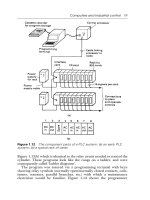
A.1.3 Functional characteristics
A.1.3.1 Basic functional structure of a PLC system
The structure of a PLC system and communication interfaces are illustrated in Figure A.1,
Figure A.2 and Figure A.3. These models are the basis of IEC 61131-2 on hardware, IEC
61131-3 on programming, IEC 61131-5 on communication and IEC 61131-7 on fuzzy
programming.
Copyright International Electrotechnical Commission
Provided by IHS under license with IEC
Licensee=Technip Abu Dabhi/5931917101
Not for Resale, 02/12/2006 07:04:26 MST
No reproduction or networking permitted without license from IHS
``,`,`,,,``````,,``,,``,,,,`,-`-`,,`,,`,`,,`
TR 61131-4 IEC:2004(E) – 21 –
Figure A.1 – Basic functional structure of a PLC system
Power
supply
function
Mains
supply
Other systems
INTERFACE functions to
sensors and actuators
Machine/Process
Application
programmer
Operator
Communication
functions
Programming
debugging and
testing functions
Man-machine
interface
functions
Data
storage
functions
Application
program
storage functions
Operating
system
functions
Application
program
Execution
Signal
processing
functions
IEC 1028/04
Copyright International Electrotechnical Commission
Provided by IHS under license with IEC
Licensee=Technip Abu Dabhi/5931917101
Not for Resale, 02/12/2006 07:04:26 MST
No reproduction or networking permitted without license from IHS
``,`,`,,,``````,,``,,``,,,,`,-`-`,,`,,`,`,,`
– 22 – TR 61131-4 IEC:2004(E)
Figure A.2 – PLC hardware model
The CPU function consists of the application program storage, the data storage, the operating
system, the execution of the application program function and processes signals obtained
from sensors as well as internal data storage and generates signals to actuators as well as
internal data storage in accordance with the application program. These include:
– Interface function to sensors and actuators converts I/O signals including pre-processed
signal from special modules such as PID, fuzzy control module, high speed counter
module, and motion module.
– Communication function provides the data exchange with other systems (third party
devices) such as other PLC systems, robot controllers, computers, etc.
– Human-Machine Interface (HMI) function provides for interaction between the operator,
the signal processing function and the machine/process.
– Programming, debugging, testing and documentation functions provide for application
program generation and loading, monitoring, testing and debugging as well as for
application program documentation and archiving.
– Power supply functions.
Memory (ies)
and
processing unit(s)
Input module(s)
Output module(s)
Communication module(s)
Power supply unit(s)
Main processing unit
Remote I/O station(s)
Peripherals
Implementer-specific subsystem(s)
IEC 1029/04
Copyright International Electrotechnical Commission
Provided by IHS under license with IEC
Licensee=Technip Abu Dabhi/5931917101
Not for Resale, 02/12/2006 07:04:26 MST
No reproduction or networking permitted without license from IHS
``,`,`,,,``````,,``,,``,,,,`,-`-`,,`,,`,`,,`
TR 61131-4 IEC:2004(E) – 23 –
Limit of the scope of this standard
Interfaced devices and signals
Open communication signals
interface/port
(internal communications also open
to third party devices
Be
H
K
G
Bi
Be
Be
Be
Bi
Bi
Bi
G
H
H
Auxiliary Power
Supply (optional)
Functional earthing port
Protective earthing port
Peripheral
(permanently /non-permanently installed)
Mains power input interface/port
Digital and analog
input signal interface/port
I/O power interface/port
I/O power interface/port
Digital and analog
output signal interface/port
Communication signals interface/port
with third party devices
(computers, printers, fieldbus
, etc)
Auxiliary power output interface/port
(to provide energy for sensors
and actuators)
Input
Module(s)
Commu
-
nication
Modules
(optional)
Memory
(
ies
)
and
Processing
Unit(s)
Power Supply
Local extension
rack
Basic PLC
Remote
IOs
Output
Module(s)
A
l
Ar
C
C
C
C
G
G
H
F
F
F
F
E
E
E
E
D
D
D
D
K
K
K
J
J
J
J
J
J
J
J
Figure A.3 – Typical interface/port diagram of a PLC system
A.1.3.2 Characteristics of the CPU function
A.1.3.2.1 Programmable functions
Capabilities of a PLC are determined by programmable functions of the CPU, summarised in
Table A.1.
IEC 1030/04
Copyright International Electrotechnical Commission
Provided by IHS under license with IEC
Licensee=Technip Abu Dabhi/5931917101
Not for Resale, 02/12/2006 07:04:26 MST
No reproduction or networking permitted without license from IHS
``,`,`,,,``````,,``,,``,,,,`,-`-`,,`,,`,`,,`