Programmable Controllers an engineer guide P2
Bạn đang xem bản rút gọn của tài liệu. Xem và tải ngay bản đầy đủ của tài liệu tại đây (1.07 MB, 20 trang )
Computers and industrial control 19
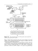
Figure 1.13(b) which is identical to the relay circuit needed to control the
cylinder. These programs look like the rungs on a ladder, and were
consequently called ‘ladder diagrams’.
The program was entered via a programming terminal with keys
showing relay symbols (normally open/normally closed contacts, coils,
timers, counters, parallel branches, etc.) with which a maintenance
electrician would be familiar. Figure 1.14 shows the programmer
Figure 1.12 The component parts of a PLC system: (a) an early PLC
system; (b) a typical rack of cards
075065757X-ch001.fm Page 19 Wednesday, July 9, 2003 3:31 PM
20 Programmable Controllers
keyboard for an early PLC. The meaning of the majority of the keys
should be obvious. The program, shown exactly on the screen as in
Figure 1.13(b), would highlight energized contacts and coils, allowing
the programming terminal to be used for simple fault finding.
The processor memory was protected by batteries to prevent
corruption or loss of program during a power fail. Programs could be
stored on cassette tapes which allowed different operating procedures
(and hence programs) to be used for different products.
The name given to these machines was ‘programmable controllers’ or
PCs. The name ‘programmable logic controller’ or PLC was also used,
but this is, strictly, a registered trademark of the Allen Bradley Company.
Unfortunately in more recent times the letters PC have come to be used
Figure 1.13 A simple PLC application. (a) A simple hydraulic cylinder
controlled by a PLC. (b) The ‘ladder diagram’ program used to control the
cylinder. This is based on American relay symbols. –][– means that signal
is present, and –]/[– means that signal is not present
075065757X-ch001.fm Page 20 Wednesday, July 9, 2003 3:31 PM
Computers and industrial control 21
for personal computer, and confusingly the worlds of programmable
controllers and personal computers overlap where portable and lap-top
computers are now used as programming terminals. To avoid confusion,
we shall use PLC for a programmable controller and PC for a personal
computer. Section 2.12 gives examples of programming software on
modern PCs.
1.4 Input/output connections
1.4.1 Input cards
Internally a computer usually operates at 5 V DC. The external devices
(solenoids, motor starters, limit switches, etc.) operate at voltages up to
110 V AC. The mixing of these two voltages will cause severe and
possibly irreparable damage to the PLC electronics. Less obvious
problems can occur from electrical ‘noise’ introduced into the PLC from
voltage spikes on signal lines, or from load currents flowing in AC
neutral or DC return lines. Differences in earth potential between the
PLC cubicle and outside plant can also cause problems.
The question of noise is discussed at length in Chapter 8, but there
are obviously very good reasons for separating the plant supplies from the
PLC supplies with some form of electrical barrier as in Figure 1.15. This
ensures that the PLC cannot be adversely affected by anything happening
on the plant. Even a cable fault putting 415 V AC onto a DC input would
only damage the input card; the PLC itself (and the other cards in the
system) would not suffer.
This is achieved by optical isolators, a light-emitting diode and photo-
electric transistor linked together as in Figure 1.16(a). When current is
passed through the diode D1 it emits light, causing the transistor TR1 to
Figure 1.14 The programming terminal keypad for an early Allen
Bradley PLC (reproduced by permission of Allen Bradley)
075065757X-ch001.fm Page 21 Wednesday, July 9, 2003 3:31 PM
22 Programmable Controllers
switch on. Because there are no electrical connections between the diode
and the transistor, very good electrical isolation (typically 1–4kV) is
achieved.
A DC input can be provided as in Figure 1.16(b). When the push-
button is pressed, current will flow through D1, causing TR1 to turn on,
passing the signal to the PLC internal logic. Diode D2 is a light-emitting
diode used as a fault-finding aid to show when the input signal is present.
Such indicators are present on almost all PLC input and output cards.
The resistor R sets the voltage range of the input. DC input cards are
usually available for three voltage ranges: 5V (TTL), 12–24 V, 24–50V.
A possible AC input circuit is shown in Figure 1.16(c). The bridge
rectifier is used to convert the AC to full wave rectified DC. Resistor R
2
and capacitor C1 act as a filter (of about 50ms time constant) to give
a clean signal to the PLC logic. As before, a neon LP1 acts as an input
signal indicator for fault finding, and resistor R
1
sets the voltage range.
Figure 1.17(a) shows a typical input card from the Allen Bradley
range. The isolation barrier and monitoring LEDs can be clearly seen.
This card handles eight inputs and could be connected to the outside
world as in Figure 1.17(b).
1.4.2 Output connections
Output cards again require some form of isolation barrier to limit
damage from the inevitable plant faults and also to stop electrical ‘noise’
corrupting the processor’s operations. Interference can be more of
a problem on outputs because higher currents are being controlled by
Figure 1.15 Protection of the PLC from outside faults. The PLC supply
L1/N1 is separate from the plant supply L2/N2
075065757X-ch001.fm Page 22 Wednesday, July 9, 2003 3:31 PM
Computers and industrial control 23
Figure 1.16 Optical isolation of inputs: (a) an optical isolator;
(b) DC input card; (c) AC input card
075065757X-ch001.fm Page 23 Wednesday, July 9, 2003 3:31 PM
24 Programmable Controllers
Figure 1.17 A PLC input card: (a) Allen Bradley eight-way input card;
(b) wiring of input card
075065757X-ch001.fm Page 24 Wednesday, July 9, 2003 3:31 PM
Computers and industrial control 25
the cards and the loads themselves are often inductive (e.g. solenoid and
relay coils).
There are two basic types of output card. In Figure 1.18(a), eight
outputs are fed from a common supply, which originates local to the
PLC cubicle (but separate from the supply to the PLC itself). This
arrangement is the simplest and the cheapest to install. Each output has
its own individual fuse protection on the card and a common circuit
breaker. It is important to design the system so that a fault, say, on load
3 blows the fuse FS3 but does not trip the supply to the whole card,
shutting down every output. This topic, called ‘discrimination’, is
discussed further in Chapter 8.
A PLC frequently has to drive outputs which have their own individual
supplies. A typical example is a motor control centre (MCC) where each
starter has a separate internal 110-V supply derived from the 415-V bars.
The card arrangement of Figure 1.18(a) could not be used here without
separate interposing relays (driven by the PLC with contacts into the
MCC circuit).
An isolated output card, shown in Figure 1.18(b), has individual out-
puts and protection and acts purely as a switch. This can be connected
directly with any outside circuit. The disadvantage is that the card is
more complicated (two connections per output) and safety becomes
more involved. An eight-way isolated output card, for example, could
have voltage on its terminals from eight different locations.
Contacts have been shown on the outputs in Figure 1.18. Relay
outputs can be used (and do give the required isolation) but are not
particularly common. A relay is an electromagnetic device with moving
parts and hence a finite limited life. A purely electronic device will have
greater reliability. Less obviously, though, a relay-driven inductive load
can generate troublesome interference and lead to early contact failure.
A transistor output circuit is shown in Figure 1.19(a). Optical isolation
is again used to give the necessary separation between the plant and the
PLC system. Diode D1 acts as a spike suppression diode to reduce the
voltage spike encountered with inductive loads. Figure 1.19(b) shows
the effect. The output state can be observed on LED1. Figure 1.19(a) is a
current sourcing output. If NPN transistors are used, a current sinking
card can be made as in Figure 1.19(c).
AC output cards invariably use triacs, a typical circuit being shown in
Figure 1.20(a). Triacs have the advantage that they turn off at zero
current in the load, as shown in Figure 1.20(b), which eliminates the
interference as an inductive load is turned off. If possible, all AC loads
should be driven from triacs rather than relays.
Figure 1.21 is a photograph of the construction of AC and DC output
cards; the isolation barrier, the state indication LEDs and the protection
fuses can be clearly seen.
075065757X-ch001.fm Page 25 Wednesday, July 9, 2003 3:31 PM
26 Programmable Controllers
Figure 1.18 Types of output card: (a) output card with common supply;
(b) output card with separate supplies
075065757X-ch001.fm Page 26 Wednesday, July 9, 2003 3:31 PM